Page is loading ...

Model #s:
5300, 5400, 5410, 5700, 5800, 5810,
5900, 5910, 5930, 5940
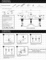
CONTEMPORARY PLP PULLDOWN FAUCET
INSTALLATION INSTRUCTIONS
5700 5800
5810 5940
5930
59005400
59405410
5300

PULLDOWN FAUCET INSTALLATION
1 2 3 4
Turn o water supply. Observe all local
plumbing codes.
Inspect plumbing for signs of
damage. Replace as necessary.
DO NOT use petroleum based
products on this faucet.
REQUIRED TOOLS:
Phillips ScrewdriverAdjustable Wrench
Channel Locks
BEFORE YOU BEGIN YOUR INSTALLATION:
Waterstone faucets are designed to be installed in 3 dierent faucet
positions. Choose to have the handle on left, front or right. Your faucet is
factory congured for the most common positions - a front and right side
installation. To reverse this and have the handle positioned on the left,
connect the hose for cold water to the hot supply and the hose for hot water
to the cold supply. This will maintain the relationship of pulling the handle
for hot water or pushing for cold water.
HANDLE POSITION
HANDLE ON LEFT HANDLE IN FRONT HANDLE ON RIGHT
B
F
COUNTER
OR SINK
2. 3. 4.
D
E
A
C
1.
A
B
C
Remove the clamp nut (A) and
washer (B) from the threaded
shroud (C).
Slide washer and thread the
clamp nut onto threaded shroud.
Tighten nut snug to underside of
sink or counter.
Turn faucet to the desired handle
position. Securely tighten clamp
screws (F).
Fit exible hoses (D) and spray
connection tube (E) through hole
on counter or sink. (No plumbers
putty is required. O-ring seals base).

CONNECT THE PULLDOWN SPRAY HOSE
Before connecting supply hoses,
ush supply stops to clear any
debris. Place a bucket underneath
stops and run water for 5 to 10
seconds. Turn water o. Carefully
position hot and cold supplies so
they will not interfere with other
hoses. Connect supply hoses (A)
to supply stops (B). DO NOT use
teon tape or plumbers putty.
Turn water back on and check for
leaks.
CONNECTING SUPPLY HOSES
A
B
HANDLE ON LEFT HANDLE IN FRONT HANDLE ON RIGHT
ORIGINAL FACTORY POSITION
MAY HIT BACKSPLASH
NEW ADJUSTED POSITION
CLEARS BACKSPLASH
H C
A
B
C D
A B E
E
G
C D F
F
HOW TO ADJUST HANDLE POSITION AND HANDLE TENSION
On some kitchen countertops, the handle may hit the
backsplash when the faucet handle is positioned to the left
or right (Fig. 1). Waterstone gives you the option of adjusting
the handle 22.5 degrees to avoid hitting backsplash.
FIG.1
RED FOR HOT
BLUE FOR COLD
OPTIONAL HOT COLD INDICATOR RING
To reverse, or remove Hot and Cold Indicator Ring,
unscrew the metal cap, remove ring and ip. Slide ring
back onto handle and screw metal cap back on.
Unscrew and remove metal cap (A) and Hot and Cold Indicator Ring (B). Unscrew and
remove holding screw (C) and washer (D). Hold handle (E) in a vertical position. Wiggle
and pull straight o faucet. Rotate handle 22 degrees away from backsplash then slide
handle back onto valve stem (F). Insert holding screw with washer and tighten. Slide
Hot and Cold Indicator Ring onto handle and thread metal cap back into place. To adjust
handle tension, turn ring (G) clockwise to increase
or counterclockwise to decrease.
HANDLE ON LEFT HANDLE IN FRONT HANDLE ON RIGHT
ORIGINAL FACTORY POSITION
MAY HIT BACKSPLASH
NEW ADJUSTED POSITION
CLEARS BACKSPLASH
H C
A
B
C D
A B E
E
G
C D F
F
B
A
C
Connect spray hose (A) to spray
connection hose tube (B).
NOTE – make sure spray hose
(A) and counter balance (C) are
free to slide up and down and
are not in conict with any
plumbing components or
items under sink.

CLEANING DEBRIS SCREEN
B
C
A
1. Gently unscrew and remove spout tip (A) by hand.
2. Remove O-ring (B). To remove aerator (C), push with nger from bottom.
3. Thoroughly rinse aerator with water until all debris is removed.
4. Place aerator, then O-ring back into spout tip.
5. Gently screw spout tip, by hand, snuggly back onto spout.
CLEANING AERATOR - TOGGLE SPRAYER
B
C
A
1. 3. 4.
2. 5.
1. Turn o water supplies
underneath sink and remove
any water pressure by opening
the faucet handle.
2. Unscrew sprayer (A) from
spray hose by holding knurled
swivel (B).
3. Inspect, remove and clean
debris screen (C) in sprayer.
Once cleaned, replace debris
screen and reattach to swivel.
4. Close faucet handle and turn
on water supplies. Make sure
sprayer is secure and sealed by
running faucet.
B
C
D
A
1. 2. 3.
4.
1. Gently unscrew and remove spray face (A) by hand.
2. To remove O-ring (B), aerator (C) and spray face insert (D), push with nger from bottom.
3. Thoroughly rinse aerator with water until all debris is removed.
4. Place spray face insert back into spray face and spin until it clicks into place. Next, place
aerator and O-ring into spray face. Gently screw spray face, by hand, snuggly back onto sprayer.
CLEANING AERATOR - LEVER SPRAYER

COUNTER
OR SINK
1-3/8”
HOLE
A
B
C
D
F
G
E
B
C
COUNTER
OR SINK
1-1/2”
HOLE
A
EXPOSE
THREADS
D
1.
2.
3. 4.
1.
2.
3.
4.
5.
6.
INSTALL AIR SWITCH (OPTIONAL)
INSTALL SOAP/LOTION DISPENSER (OPTIONAL)
Fill plastic bottle with soap or lotion. Thread
bottle (E) into bottom of dispenser shroud.
Pull and remove spout
(A) from dispenser body
(B). Remove clamp nut
(C) and brass spacer (D)
from threaded shroud.
Slide red tubing (F)
into tube tting (G)
at bottom of spout.
Insert open end of
red tubing down
through dispenser
base and into
plastic bottle.
Push down on spout
to secure over white
O-rings.
Pump spout a few
times to get soap or
lotion owing.
Fit dispenser body through 1-3/8” hole
on counter or sink. (No plumbers putty is
required). Slide brass spacer onto shroud.
Screw clamp nut and tighten snug.
Slide washer up then screw the
clamp nut onto threaded shroud.
Hand tighten nut to underside of
sink or counter until snug.
Slide clear tubing
(B) into tube
tting (C) at
bottom of air
switch shroud.
CONTINUED ON NEXT PAGE
Fit air switch and tubing through
1-1/2” hole on counter or sink.
(No plumbers putty is required.
O-ring seals base).
Before inserting air switch into
hole, loosen switch base (A)
until threads are exposed.

F
G
GARBAGE DISPOSAL
E
A
B
C
D
E
F
G
H
1-1/2”
HOLE
E
5.
6.
7. 8.
1.
2.
3.
4.
5.
6.
Unscrew and remove
top clamp nut (D)
from both threadings
on piping. Slide
gasket (E) o piping
and remove.
Twist and pull air gap
cover (A) o of upper
cap nut (B). Unscrew
and remove cap nut
from piping (C).
Slide gasket down and screw top clamp
nut back onto piping. Adjust the two
clamp nuts to t countertop thickness.
(No plumbers putty is required).
Screw cap nut back
onto top of piping
until snug. Slide air
gap over cap nut and
top clamp nut. Be
sure to have overow
holes (F) facing sink.
Slide small intake hose
(G) over small connector.
Slide larger drainage hose
(H) over large connector.
Tighten hose clamps.
Turn on water supply
and check for leaks.
From underneath
counter top, t air
gap piping upward
through 1-1/2”
hole.
CONTINUED FROM PREVIOUS PAGE
INSTALL SINGLE PORT AIR GAP (OPTIONAL)
Tighten clamp screws (E)
securely with screwdriver.
Hand tighten switch base back
down to cover threads.
Slide other end of
tubing (F) into tube
tting at bottom of
control box (G).
Plug control box into undersink
electrical outlet. Plug garbage
disposal into either dual outlet.

VEN-038-CPLP Rev. A41180 Raintree Court • Murrieta, CA 92562 • 1-888-304-0660 • 951-304-0520 •www.waterstoneco.com
G
H
L
M
K
J
A
D
E
C
B
F
1-1/2”
HOLE
1.
2.
3. 4.
5.
6.
Unscrew and remove top clamp
nut (D) from both threadings on
piping. Slide gasket (E) o piping
and remove.
Pull air gap (A) o of upper cap
nut (B). Unscrew and remove
cap nut from piping (C).
Slide gasket down and screw
top clamp nut back onto piping.
Adjust the two clamp nuts to
t countertop thickness. (No
plumbers putty is required).
Screw cap nut back onto
top of piping until snug.
Slide air gap over cap
nut and top clamp nut.
Be sure to have overow
holes (F) facing sink.
From underneath counter
top, t air gap piping upward
through 1-1/2” hole.
Slide small intake hose (G) over small connector.
Slide larger drainage hose (H) over large
connector. Tighten hose clamps.
Third intake hole (J)
has 3 options. Use
hose connector (K) for
additional dishwasher,
use ltration hose
connector (L) for reverse
osmosis unit, or use
solid cap (M) to plug
third hole.
INSTALL DUAL PORT AIR GAP (OPTIONAL)
/