DFI WL171/WL173 Owner's manual
- Category
- Motherboards
- Type
- Owner's manual
This manual is also suitable for

WL171/WL173
A-569-M-2018
Mini-ITX Industrial Motherboard
User’s Manual

2User's Manual | WL171/WL173
Copyright
This publication contains information that is protected by copyright. No part of it may be re-
produced in any form or by any means or used to make any transformation/adaptation without
the prior written permission from the copyright holders.
This publication is provided for informational purposes only. The manufacturer makes no
representations or warranties with respect to the contents or use of this manual and spe-
cifically disclaims any express or implied warranties of merchantability or fitness for any par-
ticular purpose. The user will assume the entire risk of the use or the results of the use of this
document. Further, the manufacturer reserves the right to revise this publication and make
changes to its contents at any time, without obligation to notify any person or entity of such
revisions or changes.
Changes after the publication’s first release will be based on the product’s revision. The web-
site will always provide the most updated information.
© 2020. All Rights Reserved.
Trademarks
Product names or trademarks appearing in this manual are for identification purpose only and
are the properties of the respective owners.
FCC and DOC Statement on Class B
This equipment has been tested and found to comply with the limits for a Class B digital de-
vice, pursuant to Part 15 of the FCC rules. These limits are designed to provide reasonable
protection against harmful interference when the equipment is operated in a residential in-
stallation. This equipment generates, uses and can radiate radio frequency energy and, if not
installed and used in accordance with the instruction manual, may cause harmful interference
to radio communications. However, there is no guarantee that interference will not occur in a
particular installation. If this equipment does cause harmful interference to radio or television
reception, which can be determined by turning the equipment off and on, the user is encour-
aged to try to correct the interference by one or more of the following measures:
• Reorient or relocate the receiving antenna.
• Increase the separation between the equipment and the receiver.
• Connect the equipment into an outlet on a circuit different from that to which the re-
ceiver is connected.
• Consult the dealer or an experienced radio TV technician for help.
Notice:
1. The changes or modifications not expressly approved by the party responsible for com-
pliance could void the user’s authority to operate the equipment.
2. Shielded interface cables must be used in order to comply with the emission limits.

3User's Manual | WL171/WL173
Table of Contents
Chapter 1 - Introduction ....................................................................................................................... 6
Specifications ..................................................................................................................................6
Features ............................................................................................................................................7
DDR4 ........................................................................................................................................... 7
Chapter 2 - Hardware Installation ...................................................................................................... 8
Board Layout .................................................................................................................................... 8
LEDs ...................................................................................................................................................8
System Memory ...............................................................................................................................9
Installing the SO-DIMM Module ...........................................................................................9
Heatsink ......................................................................................................................................... 10
Jumper Settings ........................................................................................................................... 12
Clear CMOS (JP1) .................................................................................................................. 12
LCD/Inverter Power Select (JP5) ....................................................................................... 12
Panel Power Select (JP4) .................................................................................................... 13
Backlight Brightness Select (JP3) ..................................................................................... 13
COM1 Power Select .............................................................................................................. 14
Auto Power-on Select (JP6) ............................................................................................... 14
Rear I/O Ports ............................................................................................................................... 15
DC In ........................................................................................................................................ 15
USB Ports ................................................................................................................................ 16
Graphics Display.................................................................................................................... 16
RJ45 LAN ................................................................................................................................ 17
Audio ....................................................................................................................................... 17
Internal I/O Connectors .............................................................................................................. 18
COM (Serial) Port .................................................................................................................. 18
USB Ports ................................................................................................................................ 18
Front Audio ............................................................................................................................ 19
SATA (Serial ATA) .................................................................................................................. 19
Chassis Intrusion ................................................................................................................... 20
CPU FAN & SYS_FAN ............................................................................................................. 20
Front Panel ............................................................................................................................. 21
SMBus...................................................................................................................................... 21
Battery .................................................................................................................................... 22
Digital I/O ............................................................................................................................... 22
LVDS Panel ............................................................................................................................. 23
eDP ........................................................................................................................................... 24
Expansion Slots ..................................................................................................................... 25
Installing the M.2 Module ................................................................................................... 25
LPC ........................................................................................................................................... 26
Chapter 3 - BIOS Settings ................................................................................................................. 27
Overview ....................................................................................................................................... 27
Main ................................................................................................................................................ 28
Advanced ...................................................................................................................................... 28
RC ACPI Configuration ......................................................................................................... 29
CPU Configuration ................................................................................................................ 29
Power & Performance .......................................................................................................... 30
PCH-FW Configuration ......................................................................................................... 30
Trusted Computing ............................................................................................................... 31
PTN3460 Configuration ....................................................................................................... 31
NCT6116D Super IO Configuration.................................................................................... 32
NCT6116D HW Monitor........................................................................................................ 33
Serial Port Console Redirection ......................................................................................... 34
USB Configuration ................................................................................................................ 35
CSM Configuration ................................................................................................................ 36
USB Power Control ............................................................................................................... 36
Network Stack Configuration ............................................................................................. 37
Chipset ........................................................................................................................................... 38
Graphics Configuration ........................................................................................................ 38
PCH-IO Configuration ........................................................................................................... 39
PCI Express Configuration ................................................................................................... 39
SATA And RST Configuration .............................................................................................. 40
HD Audio Configuration....................................................................................................... 40
Security .......................................................................................................................................... 41
Secure Boot ............................................................................................................................ 41
Boot ................................................................................................................................................ 43
Save & Exit .................................................................................................................................... 43
Updating the BIOS ....................................................................................................................... 44
Notice: BIOS SPI ROM .................................................................................................................. 44
Chapter 4 - RAID .................................................................................................................................. 45
Setup Procedure ........................................................................................................................... 45

4User's Manual | WL171/WL173
About this Manual
This manual can be downloaded from the website.
The manual is subject to change and update without notice, and may be based on editions that
do not resemble your actual products. Please visit our website or contact our sales representa-
tives for the latest editions.
Warranty
1. Warranty does not cover damages or failures that arised from misuse of the product,
inability to use the product, unauthorized replacement or alteration of components
and product specifications.
2. The warranty is void if the product has been subjected to physical abuse, improper in-
stallation, modification, accidents or unauthorized repair of the product.
3. Unless otherwise instructed in this user’s manual, the user may not, under any circum-
stances, attempt to perform service, adjustments or repairs on the product, whether
in or out of warranty. It must be returned to the purchase point, factory or authorized
service agency for all such work.
4. We will not be liable for any indirect, special, incidental or consequential damages to
the product that has been modified or altered.
Static Electricity Precautions
It is quite easy to inadvertently damage your PC, system board, components or devices even
before installing them in your system unit. Static electrical discharge can damage computer
components without causing any signs of physical damage. You must take extra care in han-
dling them to ensure against electrostatic build-up.
1. To prevent electrostatic build-up, leave the system board in its anti-static bag until
you are ready to install it.
2. Wear an antistatic wrist strap.
3. Do all preparation work on a static-free surface.
4. Hold the device only by its edges. Be careful not to touch any of the components, con-
tacts or connections.
5. Avoid touching the pins or contacts on all modules and connectors. Hold modules or
connectors by their ends.
Safety Measures
• To avoid damage to the system, use the correct AC input voltage range.
• To reduce the risk of electric shock, unplug the power cord before removing the sys-
tem chassis cover for installation or servicing. After installation or servicing, cover
the system chassis before plugging the power cord.
Important:
Electrostatic discharge (ESD) can damage your processor, disk drive and other
components. Perform the upgrade instruction procedures described at an ESD
workstation only. If such a station is not available, you can provide some ESD pro-
tection by wearing an antistatic wrist strap and attaching it to a metal part of the
system chassis. If a wrist strap is unavailable, establish and maintain contact with
the system chassis throughout any procedures requiring ESD protection.

5User's Manual | WL171/WL173
About the Package
The package contains the following items. If any of these items are missing or damaged,
please contact your dealer or sales representative for assistance.
• One WL171/WL173 board
• One COM port cable (Length: 250mm, 2*5 pin headers to DB9)
• One Serial ATA data with power cable (Length: 300mm)
• One Heatsink (Height: 25mm)
• An RS232 extension part is integrated on the board.
• Heatsink A71-008155-010G, 141.2*82*36mm, SPRING-SCREW TYPE, FOR WL171 Wide
Temp
• Heatsink A71-008155-000G, 141.2*82*26mm, SPRING-SCREW TYPE, FOR WL171
The board and accessories in the package may not come similar to the information listed
above. This may differ in accordance with the sales region or models in which it was sold. For
more information about the standard package in your region, please contact your dealer or
sales representative.
Optional Items
• USB 2.0 cable
• COM cable
• SATA cable
• Heatsink (Height: 32mm)
• I/O Shield
The board and accessories in the package may not come similar to the information listed
above. This may differ in accordance with the sales region or models in which it was sold. For
more information about the standard package in your region, please contact your dealer or
sales representative.
Before Using the System Board
When installing the system board in a new system, you will need at least the following internal
components.
• Memory module
• Storage device such as hard disk drive, CD-ROM, etc.
• Power adaptor
External system peripherals may also be required for navigation and display, including at least
a keyboard, a mouse and a video display monitor.

6
Chapter 1
INTRODUCTION
User's Manual | WL171/WL173
Chapter 1 - Introduction
X Specifications
The specifications listed here may be based on editions that do not re-
semble your actual products. Please visit the download page at go.dfi.
com/WL17x, or via the QR code to the right for the latest datasheet.
SYSTEM Processor 8th Generation Intel
®
Core™ Processors, BGA 1528
i7-8665UE, Quad Core, 8M Cache, 1.7GHz (4.4GHz), 15W
i5-8365UE, Quad Core, 6M Cache, 1.6GHz (4.1GHz), 15W
i3-8145UE, Dual Core, 4M Cache, 2.2GHz (3.9GHz), 15W
Celeron
®
4305UE, Dual Core, 2M Cache, 2.0GHz (2.0GHz), 15W
Memory 2 x 260-pin SODIMM up to 64GB
DDR4 2400MHz/DDR4 2133MHz (for Celeron 4305UE)
BIOS AMI SPI 128Mbit
GRAPHICS Controller Intel
®
UHD Graphics 620/ Intel
®
UHD Graphics 610 (for Celeron
4305UE)
Feature OpenGL 4.4, DirectX 12, OpenCL 2.1
HW Decode: AVC/H.264, MPEG2, VC1/WMV9, JPEG/MJPEG,
HEVC/H265, VP8, VP9
HW Encode: AVC/H.264, MPEG2, JPEG, HEVC/H265, VP8, VP9
Display 1 x LVDS resolution up to 1920x1200 @ 60Hz
2 x HDMI/DP, resolution up to 4096x2160 @ 30Hz
Triple
Displays
HDMI/DP++ + HDMI/DP++ + LVDS
EXPANSION Interface 1 x PCIe x4 (Gen 3)
1 x M.2 2242/2260/2280 M key (SATA3.0/PCIe x4)
1 x M.2 2230 E key (PCIe x1/USB 2.0)
AUDIO Codec Realtek ALC888S-VD2-GR
ETHERNET Controller 1 x Intel
®
I210AT PCIe (10/100/1000Mbps)
1 x Intel
®
I219LM PCIe with iAMT11.6 and vPro
(10/100/1000Mbps) (only Core i7/i5 supports iAMT)
REAR I/O Ethernet 2 x GbE (RJ-45)
USB 4 x USB 3.1 Gen2
Display 2 x HDMI/DP
Audio 1 x Line-out
1 x Mic-in
INTERNAL I/O Serial 1 x RS-232/422/485 (RS-232 w/ power) (2.0mm pitch)
1 x RS-232 (2.0mm pitch)
USB 4 x USB 2.0 (2.0mm pitch)
Display 1 x LVDS Box Header or 1 x eDP Header
Audio 1 x S/PDIF
1 x Front Audio Header
SATA 2 x SATA 3.0 (up to 6Gb/s)
2 x SATA Power
RAID 0/1
DIO 1 x 8-bit DIO
LPC 1 x LPC
SMBus 1 x SMBus
WATCHDOG
TIMER
Output &
Interval
System Reset, Programmable via Software from 1 to 255 Sec-
onds
SECURITY TPM TPM 2.0 (Opt.)
POWER Type Single 12V +/-10% DC (WL171)
Wide Range 9~36V (WL173)
Connector DC-in Jack
Right Angle Connector (4-pin) (available upon request)
Straight Type Connector (4-pin) (available upon request)
RTC Battery CR2032 Coin Cell
OS SUPPORT Microsoft/
Linux
Windows 10 IoT Enterprise 64-bit
Debian 8 (with VESA graphic driver)
Fedpra
CentOS 7 (with VESA graphic driver)
Yocto 2.6
Linux
MECHANICAL Humidity Operating: 5 to 90% RH
Dimensions Mini-ITX Form Factor: 170mm (6.7") x 170mm (6.7")
Height PCB: 1.6mm; Top Side: 16.5mm, Bottom Side: 3.5mm

7
Chapter 1
INTRODUCTION
User's Manual | WL171/WL173
X Features
Watchdog Timer
The Watchdog Timer function allows your application to regularly “clear” the system at the set
time interval. If the system hangs or fails to function, it will reset at the set time interval so
that your system will continue to operate.
DDR4
DDR4 delivers increased system bandwidth and improves performance. The advantages of
DDR4 provide an extended battery life and improve the performance at a lower power than
DDR3/DDR2.
Graphics
The integrated Intel
®
UHD graphics engine delivers an excellent blend of graphics performance
and features to meet business needs. It provides excellent video and 3D graphics with out-
standing graphics responsiveness. These enhancements deliver the performance and compat-
ibility needed for today’s and tomorrow’s business applications.
Serial ATA
Serial ATA is a storage interface that is compliant with SATA 1.0a specification. With speed of
up to 6Gb/s (SATA 3.0), it improves hard drive performance faster than the standard parallel
ATA whose data transfer rate is 100MB/s.
Gigabit LAN
The Intel
®
I219LM and Intel
®
I210AT Gigabit Ethernet Controllers support data transmission at
1Gbps.
Audio
The Realtek ALC888 audio codec provides 7.1 channel High Definition audio output.
Wake-On-LAN
This feature allows the network to remotely wake up a Soft Power Down (Soft-Off) PC. It is
supported via the onboard LAN port or via a PCI LAN card that uses the PCI PME (Power Man-
agement Event) signal. However, if your system is in the Suspend mode, you can power-on the
system only through an IRQ or DMA interrupt.
Wake-On-USB
This function allows you to use a USB keyboard or USB mouse to wake up a system from the S3
(STR - Suspend To RAM) state.
ACPI STR
The system board is designed to meet the ACPI (Advanced Configuration and Power Interface)
specification. ACPI has energy saving features that enables PCs to implement Power Manage-
ment and Plug-and-Play with operating systems that support OS Direct Power Management.
ACPI when enabled in the Power Management Setup will allow you to use the Suspend to RAM
function.
With the Suspend to RAM function enabled, you can power-off the system at once by pressing
the power button or selecting “Standby” when you shut down Windows
®
without having to go
through the sometimes tiresome process of closing files, applications and operating system.
This is because the system is capable of storing all programs and data files during the entire
operating session into RAM (Random Access Memory) when it powers-off. The operating ses-
sion will resume exactly where you left off the next time you power-on the system.
Power Failure Recovery
When power returns after an AC power failure, you may choose to either power-on the system
manually or let the system power-on automatically.
USB
The system board supports the new USB 3.1 Gen 2. It is capable of running at a maximum
transmission speed of up to 10 Gbit/s (1.2 GB/s) and is faster than USB 3.1 Gen 1 (5 Gbit/s, or
625 MB/s), USB 2.0 (480 Mbit/s, or 60 MB/s) and USB 1.1 (12Mb/s). USB 3.1 reduces the time
required for data transmission, reduces power consumption, and is backward compatible with
USB 2.0. It is a marked improvement in device transfer speeds between your computer and a
wide range of simultaneously accessible external Plug and Play peripherals.
RTC Timer
The Real Time Clock (RTC) installed on the system board allows your system to automatically
power-on on the set date and time.

8
Chapter 2
HARDWARE INSTALLATION
User's Manual | WL171/WL173
Chapter 2 - Hardware Installation
1
2
13
14
DDR4_2 SODIMM
DDR4_1 SODIMM
40
39 1
2
8
1
1
1
1
1
2
5
6
1
1
1
19
2
19
2
2
11
8
1
1
1
1
6
5
2
1
1
2
9
10
1
2
9
10
1
2
9
10
11
1
5
2
Line Out
Mic In
1 40
1
1
11
USB 1/2
(USB 3.0/2.0)
USB 3/4
(USB 3.0/2.0)
LAN2
LAN1
HDMI/DP++
HDMI/DP++
DC In
Note
Intel
BGA 1528
16
17 18
19
22
23
31
32
1
3
9
6
7
8
10
12
13
14
15
22
20
21
24
25
26
28
27
2930
4
5
2
33
34
35
Important:
Electrostatic discharge (ESD) can damage your board, proces-
sor, disk drives, add-in boards, and other components. Perform
installation procedures at an ESD workstation only. If such a
station is not available, you can provide some ESD protection
by wearing an antistatic wrist strap and attaching it to a metal
part of the system chassis. If a wrist strap is unavailable, es-
tablish and maintain contact with the system chassis through-
out any procedures requiring ESD protection.
Note:
Some of the components are model-specific. Please refer to the specifications for detail.
Important:
When the Standby Power LED lights up, it indicates that there
is power on the system board. Power-off the PC then unplug
the power cord prior to installing any devices. Failure to do
so will cause severe damage to the motherboard and compo-
nents.
X LEDs
Base-T LED (left),
Wireles LED (right)
SATA LED
X Board Layout
1
2
13
14
DDR4_2 SODIMM
DDR4_1 SODIMM
40
39 1
2
8
1
1
1
1
1
2
5
6
1
1
1
19
2
19
2
2
11
8
1
1
1
1
6
5
2
1
1
2
9
10
1
2
9
10
1
2
9
10
11
1
5
2
Line Out
Mic In
1
1
LED3
SATA0
SATA1
11
LPC
LVDS Inverter Power
USB 7/8 (USB 2.0)
PCIE1 (PCIe x4)
Front Audio
USB 1/2
(USB 3.0/2.0)
USB 3/4
(USB 3.0/2.0)
LAN2
LAN1
HDMI/DP++
HDMI/DP++
DC In
Note
Buzzer
JP1
JP5
JP3
LVDS
eDP(opt.)
JP4
Battery
Front Panel
DIO
SATA Power
M.2 E Key
Chassis Intrusion
COM1
COM2
SPI Flash BIOS
M.2 M Key
LED2
USB 5/6 (USB 2.0)
SMBUS
DIO Power
LED1
JP2
Intel
BGA 1528
16
17 18
19
22
23
31
32
3
9
6
7
8
10
12
13
14
15
20
20
21
24
25
26
28
27
2930
4
1
2
3
4
7
8
9
10
11
5
5
6
14
13
12
19
20
15
18
16
17
22
21
23
25
24
26
27
29
28
30
31
32
2
CPU
33
CPU FAN
33
34
34
SYS FAN
1
1

9
Chapter 2
HARDWARE INSTALLATION
User's Manual | WL171/WL173
1
2
13
14
DDR4_2 SODIMM
DDR4_1 SODIMM
40
39 1
2
8
1
1
1
1
1
2
5
6
1
1
1
19
2
19
2
2
11
8
1
1
1
1
6
5
2
1
1
2
9
10
1
2
9
10
1
2
9
10
11
1
5
2
Line Out
Mic In
1 40
1
1
11
USB 1/2
(USB 3.0/2.0)
USB 3/4
(USB 3.0/2.0)
LAN2
LAN1
HDMI/DP++
HDMI/DP++
DC In
Note
Intel
BGA 1528
16
17 18
19
22
23
31
32
1
3
9
6
7
8
10
12
13
14
15
22
20
21
24
25
26
28
27
2930
4
5
2
33
34
35
• 2 x 260-pin SODIMM up to 64GB
• DDR4 2400MHz (Celeron 4305UE 2133MHz only)
X System Memory
Features
The system board supports the following memory interface.
Single Channel (SC)
Data will be accessed in chunks of 64 bits from the memory channels.
Dual Channel (DC)
Data will be accessed in chunks of 128 bits from the memory channels. Dual channel provides
better system performance because it doubles the data transfer rate.
Single Channel DIMMs are on the same channel. DIMMs in a channel can be identi-
cal or completely different. However, we highly recommend using
identical DIMMs. Not all slots need to be populated.
Dual Channel DIMMs of the same memory configuration are on different channels.
DDR4_1
DDR4_2
Installing the SO-DIMM Module
Before installing the memory module, please make sure that the following safety cautions are
well-attended.
1. Make sure the PC and all other peripheral devices connected to it has been powered
down.
2. Disconnect all power cords and cables.
3. Locate the SO-DIMM socket on the system board
4. Make sure the notch on memory card is aligned to the key on the socket.
X System Memory
Notch
Retention Notch
Key
Socket Top View
DDR4 SO-DIMM
Retention Clip
45°
Step 1
Step 2
Step 3

10
Chapter 2
HARDWARE INSTALLATION
User's Manual | WL171/WL173
X System Memory
X Installing the SO-DIMM Module
Please follow the steps below to install the memory card into the socket.
Step 1:
Insert the memory card into the
slot while making sure 1) the
notch and the key are aligned,
and 2) the non-connector end
rises approximately 45 degrees
horizontally. Press the card firmly
into the socket while applying and
maintaining even pressure on both
ends.
Step 2:
Press the end of the card far from
the socket down while making
sure the retention notch and the
clip align as indicated by the dot-
ted line in the illustration. If the
retention notch and the clip do
not align, please remove the card
and re-insert it. Press the card all
the way down.
Step 3:
The clips snap automatically and
abruptly to the retention notches
of the card sounding a distinctive
click, and lock the card in place.
Inspect that the clip sits in the
notch. If not, please pull the clips
outward, release and remove the
card, and mount it again.
Notch
Retention Notch
Key
Socket Top View
DDR3 SO-DIMM
Retention Clip
45°
Step 1
Step 2
Step 3
X Heatsink
The CPU must be kept cool by using a heatsink, otherwise the CPU will overheat damaging
both the CPU and system board.
1. Before you install the heatsink, you must apply a thermal paste onto the top of the
CPU. The thermal paste is usually supplied when you purchase the heatsink assembly.
Do not spread the paste all over the surface. When you later place the heatsink on top
of the CPU, the compound will disperse evenly.
Some heatsinks come with a patch of pre-applied thermal paste. Do not apply thermal
paste if the heatsink already has a patch of thermal paste on its underside. Peel the
strip that covers the paste before you place the heatsink on top of the CPU.
2. Place the heatsink on top of the CPU. The 4 spring screws around the heatsink, which
are used to secure the heatsink onto the system board, must match the 4 mounting
holes around the socket.
1
2
13
14
DDR4_2 SODIMM
DDR4_1 SODIMM
40
39 1
2
8
1
1
1
1
1
2
5
6
1
1
1
19
2
19
2
2
11
8
1
1
1
1
6
5
2
1
1
2
9
10
1
2
9
10
1
2
9
10
11
1
5
2
Line Out
Mic In
1 40
1
1
11
USB 1/2
(USB 3.0/2.0)
USB 3/4
(USB 3.0/2.0)
LAN2
LAN1
HDMI/DP++
HDMI/DP++
DC In
Note
Intel
BGA 1528
16
17 18
19
22
23
31
32
1
3
9
6
7
8
10
12
13
14
15
22
20
21
24
25
26
28
27
2930
4
5
2
33
34
35
Mounting holes

11
Chapter 2
HARDWARE INSTALLATION
User's Manual | WL171/WL173
Note:
The standard package of WL171/173 only includes a heatsink.
4. Screw tight two of the spring screws at opposite corners into the mounting holes. And
then proceed with the other two spring screws.
The heatsink included in the standard package is de-
signed to dissipate heat from both the CPU and the
memory. Please orient the heatsink so that the interface
metal sits on top the CPU and the heatsink also hov-
ers the memory. The heatsink is also attached with four
spring screws.
X Heatsink
CPU
SO-DIMM
Mounting holes
Interface Metal

12
Chapter 2
HARDWARE INSTALLATION
User's Manual | WL171/WL173
1
2
13
14
DDR4_2 SODIMM
DDR4_1 SODIMM
40
39 1
2
8
1
1
1
1
1
2
5
6
1
1
1
19
2
19
2
2
11
8
1
1
1
1
6
5
2
1
1
2
9
10
1
2
9
10
1
2
9
10
11
1
5
2
Line Out
Mic In
1 40
1
1
11
USB 1/2
(USB 3.0/2.0)
USB 3/4
(USB 3.0/2.0)
LAN2
LAN1
HDMI/DP++
HDMI/DP++
DC In
Note
Intel
BGA 1528
16
17 18
19
22
23
31
32
1
3
9
6
7
8
10
12
13
14
15
22
20
21
24
25
26
28
27
2930
4
5
2
33
34
35
1
2
13
14
DDR4_2 SODIMM
DDR4_1 SODIMM
40
39 1
2
8
1
1
1
1
1
2
5
6
1
1
1
19
2
19
2
2
11
8
1
1
1
1
6
5
2
1
1
2
9
10
1
2
9
10
1
2
9
10
11
1
5
2
Line Out
Mic In
1 40
1
1
11
USB 1/2
(USB 3.0/2.0)
USB 3/4
(USB 3.0/2.0)
LAN2
LAN1
HDMI/DP++
HDMI/DP++
DC In
Note
Intel
BGA 1528
16
17 18
19
22
23
31
32
1
3
9
6
7
8
10
12
13
14
15
22
20
21
24
25
26
28
27
2930
4
5
2
33
34
35
X Jumper Settings
Clear CMOS (JP1)
If any anomaly of the followings is encountered —
a) CMOS data is corrupted;
b) you forgot the supervisor or user password;
c) failure to start the system due to BIOS mis-configuration
— it is suggested that the system be reconfigured with default values stored in the ROM BIOS.
To load the default values stored in the ROM BIOS, please follow the steps below.
1. Power-off the system and unplug the power cord.
2. Put a jumper cap on JP1’s pin 2 and pin 3. Wait for a few seconds and set JP1 back to
its default setting, i.e. jumper cap on pin 1 and pin 2.
3. Plug the power cord and power-on the system.
2-3 On: Clear CMOS 1-2 On: Normal (default)
1
2
13
14
DDR4_2 SODIMM
DDR4_1 SODIMM
40
39 1
2
8
1
1
1
1
1
2
5
6
1
1
1
19
2
19
2
2
11
8
1
1
1
1
6
5
2
1
1
2
9
10
1
2
9
10
1
2
9
10
11
1
5
2
Line Out
Mic In
1
1
LED3
SATA0
SATA1
11
LPC
LVDS Inverter Power
USB 7/8 (USB 2.0)
PCIE1 (PCIe x4)
Front Audio
USB 1/2
(USB 3.0/2.0)
USB 3/4
(USB 3.0/2.0)
LAN2
LAN1
HDMI/DP++
HDMI/DP++
DC In
Note
Buzzer
JP1
JP5
JP3
LVDS
eDP(opt.)
JP4
Battery
Front Panel
DIO
SATA Power
M.2 E Key
Chassis Intrusion
COM1
COM2
SPI Flash BIOS
M.2 M Key
LED2
USB 5/6 (USB 2.0)
SMBUS
DIO Power
LED1
JP2
Intel
BGA 1528
16
17 18
19
22
23
31
32
3
9
6
7
8
10
12
13
14
15
20
20
21
24
25
26
28
27
2930
4
1
2
3
4
7
8
9
10
11
5
5
6
14
13
12
19
20
15
18
16
17
22
21
23
25
24
26
27
29
28
30
31
32
2
CPU
33
CPU FAN
33
34
34
SYS FAN
1
1
1
2
13
14
DDR4_2 SODIMM
DDR4_1 SODIMM
40
39 1
2
8
1
1
1
1
1
2
5
6
1
1
1
19
2
19
2
2
11
8
1
1
1
1
6
5
2
1
1
2
9
10
1
2
9
10
1
2
9
10
11
1
5
2
Line Out
Mic In
1
1
LED3
SATA0
SATA1
11
LPC
LVDS Inverter Power
USB 7/8 (USB 2.0)
PCIE1 (PCIe x4)
Front Audio
USB 1/2
(USB 3.0/2.0)
USB 3/4
(USB 3.0/2.0)
LAN2
LAN1
HDMI/DP++
HDMI/DP++
DC In
Note
Buzzer
JP1
JP5
JP3
LVDS
eDP(opt.)
JP4
Battery
Front Panel
DIO
SATA Power
M.2 E Key
Chassis Intrusion
COM1
COM2
SPI Flash BIOS
M.2 M Key
LED2
USB 5/6 (USB 2.0)
SMBUS
DIO Power
LED1
JP2
Intel
BGA 1528
16
17 18
19
22
23
31
32
3
9
6
7
8
10
12
13
14
15
20
20
21
24
25
26
28
27
2930
4
1
2
3
4
7
8
9
10
11
5
5
6
14
13
12
19
20
15
18
16
17
22
21
23
25
24
26
27
29
28
30
31
32
2
CPU
33
CPU FAN
33
34
34
SYS FAN
1
1
LCD/Inverter Power Select (JP5)
2-3 On: +5V 1-2 On: +12V (default)
The power level supplied to the LVDS/eDP inverter power connector can be switched between
+5V or +12V via JP5.
Important:
Before powering-on the system, make sure that the setting of jumper matches
the specifications of the LVDS/eDP LCD. Incorrect power voltage may cause irre-
versible damage to your LCD panel.
31 2 31 2
JP1
6
31 2 31 2
JP5
7

13
Chapter 2
HARDWARE INSTALLATION
User's Manual | WL171/WL173
X Jumper Settings
X Jumper Settings
Backlight Brightness Select (JP3)
2-3 On: +5V 1-2 On: +3V3 (default)
The power level supplied to the LCD backlight can be switched between +3.3V or +5V via JP3.
Important:
Before powering-on the system, make sure that the setting of the jumper match-
es the specifications of the LCD's backlight power. Incorrect power voltage may
cause irreversible damage to your LCD's backlight.
Panel Power Select (JP4)
The power level supplied to the LVDS/eDP panel can be switched between +3.3V, +5V or +12V
via JP4.
Important:
Before powering-on the system, make sure that the setting of the jumper match-
es the specifications of the LVDS/eDP LCD. Incorrect power voltage may cause ir-
reversible damage to your LCD panel.
1-2 On: +12V 3-4 On: +5V 5-6 On: +3.3V (default)
1
2
13
14
DDR4_2 SODIMM
DDR4_1 SODIMM
40
39 1
2
8
1
1
1
1
1
2
5
6
1
1
1
19
2
19
2
2
11
8
1
1
1
1
6
5
2
1
1
2
9
10
1
2
9
10
1
2
9
10
11
1
5
2
Line Out
Mic In
1 40
1
1
11
USB 1/2
(USB 3.0/2.0)
USB 3/4
(USB 3.0/2.0)
LAN2
LAN1
HDMI/DP++
HDMI/DP++
DC In
Note
Intel
BGA 1528
16
17 18
19
22
23
31
32
1
3
9
6
7
8
10
12
13
14
15
22
20
21
24
25
26
28
27
2930
4
5
2
33
34
35
1
2
13
14
DDR4_2 SODIMM
DDR4_1 SODIMM
40
39 1
2
8
1
1
1
1
1
2
5
6
1
1
1
19
2
19
2
2
11
8
1
1
1
1
6
5
2
1
1
2
9
10
1
2
9
10
1
2
9
10
11
1
5
2
Line Out
Mic In
1
1
LED3
SATA0
SATA1
11
LPC
LVDS Inverter Power
USB 7/8 (USB 2.0)
PCIE1 (PCIe x4)
Front Audio
USB 1/2
(USB 3.0/2.0)
USB 3/4
(USB 3.0/2.0)
LAN2
LAN1
HDMI/DP++
HDMI/DP++
DC In
Note
Buzzer
JP1
JP5
JP3
LVDS
eDP(opt.)
JP4
Battery
Front Panel
DIO
SATA Power
M.2 E Key
Chassis Intrusion
COM1
COM2
SPI Flash BIOS
M.2 M Key
LED2
USB 5/6 (USB 2.0)
SMBUS
DIO Power
LED1
JP2
Intel
BGA 1528
16
17 18
19
22
23
31
32
3
9
6
7
8
10
12
13
14
15
20
20
21
24
25
26
28
27
2930
4
1
2
3
4
7
8
9
10
11
5
5
6
14
13
12
19
20
15
18
16
17
22
21
23
25
24
26
27
29
28
30
31
32
2
CPU
33
CPU FAN
33
34
34
SYS FAN
1
1
JP4
4
642
531
642
531
642
531
1
2
13
14
DDR4_2 SODIMM
DDR4_1 SODIMM
40
39 1
2
8
1
1
1
1
1
2
5
6
1
1
1
19
2
19
2
2
11
8
1
1
1
1
6
5
2
1
1
2
9
10
1
2
9
10
1
2
9
10
11
1
5
2
Line Out
Mic In
1
1
LED3
SATA0
SATA1
11
LPC
LVDS Inverter Power
USB 7/8 (USB 2.0)
PCIE1 (PCIe x4)
Front Audio
USB 1/2
(USB 3.0/2.0)
USB 3/4
(USB 3.0/2.0)
LAN2
LAN1
HDMI/DP++
HDMI/DP++
DC In
Note
Buzzer
JP1
JP5
JP3
LVDS
eDP(opt.)
JP4
Battery
Front Panel
DIO
SATA Power
M.2 E Key
Chassis Intrusion
COM1
COM2
SPI Flash BIOS
M.2 M Key
LED2
USB 5/6 (USB 2.0)
SMBUS
DIO Power
LED1
JP2
Intel
BGA 1528
16
17 18
19
22
23
31
32
3
9
6
7
8
10
12
13
14
15
20
20
21
24
25
26
28
27
2930
4
1
2
3
4
7
8
9
10
11
5
5
6
14
13
12
19
20
15
18
16
17
22
21
23
25
24
26
27
29
28
30
31
32
2
CPU
33
CPU FAN
33
34
34
SYS FAN
1
1
JP3
8
31 2 31 2

14
Chapter 2
HARDWARE INSTALLATION
User's Manual | WL171/WL173
COM1 Power Select
The COM 1 serial port supports RS232 with or without power configured via jumper settings of
JP2 (COM 1).
Standard RS232 (default) RS232 with Power
1-3 On: Pin 9 = RI-
2-4 On: Pin 1 = DCD-
3-5 On: Pin 9 = +5V
4-6 On: Pin 1 = +12V
X Jumper Settings
1
2
13
14
DDR4_2 SODIMM
DDR4_1 SODIMM
40
39 1
2
8
1
1
1
1
1
2
5
6
1
1
1
19
2
19
2
2
11
8
1
1
1
1
6
5
2
1
1
2
9
10
1
2
9
10
1
2
9
10
11
1
5
2
Line Out
Mic In
1 40
1
1
11
USB 1/2
(USB 3.0/2.0)
USB 3/4
(USB 3.0/2.0)
LAN2
LAN1
HDMI/DP++
HDMI/DP++
DC In
Note
Intel
BGA 1528
16
17 18
19
22
23
31
32
1
3
9
6
7
8
10
12
13
14
15
22
20
21
24
25
26
28
27
2930
4
5
2
33
34
35
1
2
13
14
DDR4_2 SODIMM
DDR4_1 SODIMM
40
39 1
2
8
1
1
1
1
1
2
5
6
1
1
1
19
2
19
2
2
11
8
1
1
1
1
6
5
2
1
1
2
9
10
1
2
9
10
1
2
9
10
11
1
5
2
Line Out
Mic In
1
1
LED3
SATA0
SATA1
11
LPC
LVDS Inverter Power
USB 7/8 (USB 2.0)
PCIE1 (PCIe x4)
Front Audio
USB 1/2
(USB 3.0/2.0)
USB 3/4
(USB 3.0/2.0)
LAN2
LAN1
HDMI/DP++
HDMI/DP++
DC In
Note
Buzzer
JP1
JP5
JP3
LVDS
eDP(opt.)
JP4
Battery
Front Panel
DIO
SATA Power
M.2 E Key
Chassis Intrusion
COM1
COM2
SPI Flash BIOS
M.2 M Key
LED2
USB 5/6 (USB 2.0)
SMBUS
DIO Power
LED1
JP2
Intel
BGA 1528
16
17 18
19
22
23
31
32
3
9
6
7
8
10
12
13
14
15
20
20
21
24
25
26
28
27
2930
4
1
2
3
4
7
8
9
10
11
5
5
6
14
13
12
19
20
15
18
16
17
22
21
23
25
24
26
27
29
28
30
31
32
2
CPU
33
CPU FAN
33
34
34
SYS FAN
1
1
531
642
531
642
JP2
16
COM1
17

15
Chapter 2
HARDWARE INSTALLATION
User's Manual | WL171/WL173
X Rear I/O Ports
2 x LAN Mic In
Line Out
4 x USB 3.1
2 x HDMI/DP++
DC In
The rear panel I/O ports consist of the following:
• 2 HDMI/DP++ ports
• 1 DC-In, 12V(WL171) or 9V~36V (WL173)
• 2 RJ45 LAN ports
• 4 USB 3.1 Gen2 ports
X Rear I/O Ports
DC In coaxial
The votalge range is model-specific — 12VDC for WL171, and 9V~36V for WL173.
Connect a coaxial DC power cord to the rear coaxial connector for DC supply. The 4-pin vertical
/ right-angle type is avaible upon request.
Important:
Using a voltage higher than the recommended range may result in failure in start-
ing and booting the system or causing irreversible damage to the system board.
A power adaptor/converter is necessary when the power source on site does not
comply with the power specifications of the board.
DC In
1
2
13
14
DDR4_2 SODIMM
DDR4_1 SODIMM
40
39 1
2
8
1
1
1
1
1
2
5
6
1
1
1
19
2
19
2
2
11
8
1
1
1
1
6
5
2
1
1
2
9
10
1
2
9
10
1
2
9
10
11
1
5
2
Line Out
Mic In
1 40
1
1
11
USB 1/2
(USB 3.0/2.0)
USB 3/4
(USB 3.0/2.0)
LAN2
LAN1
HDMI/DP++
HDMI/DP++
DC In
Note
Intel
BGA 1528
16
17 18
19
22
23
31
32
1
3
9
6
7
8
10
12
13
14
15
22
20
21
24
25
26
28
27
2930
4
5
2
33
34
35
DC In coaxial
4-pin vertical (optional)
4-pin right-angle (optional)

16
Chapter 2
HARDWARE INSTALLATION
User's Manual | WL171/WL173
1
2
13
14
DDR4_2 SODIMM
DDR4_1 SODIMM
40
39 1
2
8
1
1
1
1
1
2
5
6
1
1
1
19
2
19
2
2
11
8
1
1
1
1
6
5
2
1
1
2
9
10
1
2
9
10
1
2
9
10
11
1
5
2
Line Out
Mic In
1 40
1
1
11
USB 1/2
(USB 3.0/2.0)
USB 3/4
(USB 3.0/2.0)
LAN2
LAN1
HDMI/DP++
HDMI/DP++
DC In
Note
Intel
BGA 1528
16
17 18
19
22
23
31
32
1
3
9
6
7
8
10
12
13
14
15
22
20
21
24
25
26
28
27
2930
4
5
2
33
34
35
USB Ports
USB allows data exchange between your computer and a wide range of simultaneously acces-
sible external Plug and Play peripherals. The system board is equipped with our USB 3.1 Gen2
Type A ports at the rear side. For the internal USB ports, please refer to the next section.
Wake-On-USB Keyboard/Mouse
The Wake-On-USB Keyboard/Mouse function allows you to use a USB keyboard or USB mouse
to wake up a system from the S3 (STR - Suspend To RAM) state.
HDMI/DP++ 2 HDMI/DP++ 1
X Rear I/O Ports
1
2
13
14
DDR4_2 SODIMM
DDR4_1 SODIMM
40
39 1
2
8
1
1
1
1
1
2
5
6
1
1
1
19
2
19
2
2
11
8
1
1
1
1
6
5
2
1
1
2
9
10
1
2
9
10
1
2
9
10
11
1
5
2
Line Out
Mic In
1 40
1
1
11
USB 1/2
(USB 3.0/2.0)
USB 3/4
(USB 3.0/2.0)
LAN2
LAN1
HDMI/DP++
HDMI/DP++
DC In
Note
Intel
BGA 1528
16
17 18
19
22
23
31
32
1
3
9
6
7
8
10
12
13
14
15
22
20
21
24
25
26
28
27
2930
4
5
2
33
34
35
Graphics Display
The two display ports use DisplayPort connector and will auto-detect HDMI or DP signal.
HDMI
The HDMI port which carries both digital audio and video signals is used to connect a LCD
monitor or digital TV that has the HDMI port.
DisplayPort ++
The DisplayPort (DP) is a digital display interface used to connect a display device such as a
computer monitor. It is used to transmit audio and video simultaneously. The interface, which
is developed by VESA, delivers higher performance features than any other digital interface.
X Rear I/O Ports
USB 4 (USB 3.1) USB 2 (USB 3.1)
USB 3 (USB 3.1) USB 1 (USB 3.1)

17
Chapter 2
HARDWARE INSTALLATION
User's Manual | WL171/WL173
1
2
13
14
DDR4_2 SODIMM
DDR4_1 SODIMM
40
39 1
2
8
1
1
1
1
1
2
5
6
1
1
1
19
2
19
2
2
11
8
1
1
1
1
6
5
2
1
1
2
9
10
1
2
9
10
1
2
9
10
11
1
5
2
Line Out
Mic In
1 40
1
1
11
USB 1/2
(USB 3.0/2.0)
USB 3/4
(USB 3.0/2.0)
LAN2
LAN1
HDMI/DP++
HDMI/DP++
DC In
Note
Intel
BGA 1528
16
17 18
19
22
23
31
32
1
3
9
6
7
8
10
12
13
14
15
22
20
21
24
25
26
28
27
2930
4
5
2
33
34
35
1
2
13
14
DDR4_2 SODIMM
DDR4_1 SODIMM
40
39 1
2
8
1
1
1
1
1
2
5
6
1
1
1
19
2
19
2
2
11
8
1
1
1
1
6
5
2
1
1
2
9
10
1
2
9
10
1
2
9
10
11
1
5
2
Line Out
Mic In
1 40
1
1
11
USB 1/2
(USB 3.0/2.0)
USB 3/4
(USB 3.0/2.0)
LAN2
LAN1
HDMI/DP++
HDMI/DP++
DC In
Note
Intel
BGA 1528
16
17 18
19
22
23
31
32
1
3
9
6
7
8
10
12
13
14
15
22
20
21
24
25
26
28
27
2930
4
5
2
33
34
35
RJ45 LAN
The two LAN ports allow the system board to connect to a local area network.
Features
• LAN1: Intel
®
I210AT PCIe Gigabit Ethernet LAN Controller
• LAN2: Intel
®
I219LM LAN PHY
X Rear I/O Ports
LAN 1 LAN 2
Audio
X Rear I/O Ports
The system board is equipped with two rear audio jacks:
• Line-out Jack (Lime)
This jack is used to connect a headphone or external speakers.
• Mic-in Jack (Pink)
This jack is used to connect an external microphone.
The system board is equipped with two rear audio jacks:
• Line-out Jack (Lime)
This jack is used to connect a headphone or external speakers.
• Mic-in Jack (Pink)
This jack is used to connect an external microphone.
BIOS Setting
Configure the onboard audio port in the Advanced menu (“Audio Configuration” submenu) of
the BIOS. Refer to chapter 3 for more information.
Driver Installation
Install the audio driver. Refer to Chapter 4 for more information.
Mic In Line Out

18
Chapter 2
HARDWARE INSTALLATION
User's Manual | WL171/WL173
USB Ports
X Internal I/O Connectors
1
2
13
14
DDR4_2 SODIMM
DDR4_1 SODIMM
40
39 1
2
8
1
1
1
1
1
2
5
6
1
1
1
19
2
19
2
2
11
8
1
1
1
1
6
5
2
1
1
2
9
10
1
2
9
10
1
2
9
10
11
1
5
2
Line Out
Mic In
1 40
1
1
11
USB 1/2
(USB 3.0/2.0)
USB 3/4
(USB 3.0/2.0)
LAN2
LAN1
HDMI/DP++
HDMI/DP++
DC In
Note
Intel
BGA 1528
16
17 18
19
22
23
31
32
1
3
9
6
7
8
10
12
13
14
15
22
20
21
24
25
26
28
27
2930
4
5
2
33
34
35
1
2
13
14
DDR4_2 SODIMM
DDR4_1 SODIMM
40
39 1
2
8
1
1
1
1
1
2
5
6
1
1
1
19
2
19
2
2
11
8
1
1
1
1
6
5
2
1
1
2
9
10
1
2
9
10
1
2
9
10
11
1
5
2
Line Out
Mic In
1
1
LED3
SATA0
SATA1
11
LPC
LVDS Inverter Power
USB 7/8 (USB 2.0)
PCIE1 (PCIe x4)
Front Audio
USB 1/2
(USB 3.0/2.0)
USB 3/4
(USB 3.0/2.0)
LAN2
LAN1
HDMI/DP++
HDMI/DP++
DC In
Note
Buzzer
JP1
JP5
JP3
LVDS
eDP(opt.)
JP4
Battery
Front Panel
DIO
SATA Power
M.2 E Key
Chassis Intrusion
COM1
COM2
SPI Flash BIOS
M.2 M Key
LED2
USB 5/6 (USB 2.0)
SMBUS
DIO Power
LED1
JP2
Intel
BGA 1528
16
17 18
19
22
23
31
32
3
9
6
7
8
10
12
13
14
15
20
20
21
24
25
26
28
27
2930
4
1
2
3
4
7
8
9
10
11
5
5
6
14
13
12
19
20
15
18
16
17
22
21
23
25
24
26
27
29
28
30
31
32
2
CPU
33
CPU FAN
33
34
34
SYS FAN
1
1
The USB device allows data exchange between your computer and a wide range of simultane-
ously accessible external Plug and Play peripherals.
In addition to the rear USB ports as introduced previously in this chapter, the system board is
equipped with four internal USB 2.0 ports (two pin headers) as illustrated above.
The internal USB pin headers may be connected to a card-edge bracket. Install the card-edge
bracket to an available slot at the rear of the system chassis and then insert the USB port
cables to a connector.
Wake-On-USB Keyboard/Mouse
The Wake-On-USB Keyboard/Mouse function allows you to use a USB keyboard or USB mouse
to wake up a system from the S state(s).
USB 2.0 Pin Assignment
VCC
-Data
+Data
GND
Key
VCC
-Data
+Data
GND
N.C.
2
10
1
USB 7/8 (USB 2.0)
USB 5/6 (USB 2.0)
14
15
X Internal I/O Connectors
COM (Serial) Port
1
2
13
14
DDR4_2 SODIMM
DDR4_1 SODIMM
40
39 1
2
8
1
1
1
1
1
2
5
6
1
1
1
19
2
19
2
2
11
8
1
1
1
1
6
5
2
1
1
2
9
10
1
2
9
10
1
2
9
10
11
1
5
2
Line Out
Mic In
1 40
1
1
11
USB 1/2
(USB 3.0/2.0)
USB 3/4
(USB 3.0/2.0)
LAN2
LAN1
HDMI/DP++
HDMI/DP++
DC In
Note
Intel
BGA 1528
16
17 18
19
22
23
31
32
1
3
9
6
7
8
10
12
13
14
15
22
20
21
24
25
26
28
27
2930
4
5
2
33
34
35
1
2
13
14
DDR4_2 SODIMM
DDR4_1 SODIMM
40
39 1
2
8
1
1
1
1
1
2
5
6
1
1
1
19
2
19
2
2
11
8
1
1
1
1
6
5
2
1
1
2
9
10
1
2
9
10
1
2
9
10
11
1
5
2
Line Out
Mic In
1
1
LED3
SATA0
SATA1
11
LPC
LVDS Inverter Power
USB 7/8 (USB 2.0)
PCIE1 (PCIe x4)
Front Audio
USB 1/2
(USB 3.0/2.0)
USB 3/4
(USB 3.0/2.0)
LAN2
LAN1
HDMI/DP++
HDMI/DP++
DC In
Note
Buzzer
JP1
JP5
JP3
LVDS
eDP(opt.)
JP4
Battery
Front Panel
DIO
SATA Power
M.2 E Key
Chassis Intrusion
COM1
COM2
SPI Flash BIOS
M.2 M Key
LED2
USB 5/6 (USB 2.0)
SMBUS
DIO Power
LED1
JP2
Intel
BGA 1528
16
17 18
19
22
23
31
32
3
9
6
7
8
10
12
13
14
15
20
20
21
24
25
26
28
27
2930
4
1
2
3
4
7
8
9
10
11
5
5
6
14
13
12
19
20
15
18
16
17
22
21
23
25
24
26
27
29
28
30
31
32
2
CPU
33
CPU FAN
33
34
34
SYS FAN
1
1
COM1
17
COM2
18
The serial ports are asynchronous communication ports with 16C550A-compatible UARTs that
can be used with modems, serial printers, remote display terminals, and other serial devices.
COM 1 supports three serial modes, i.e. RS232 (with or without power), RS422, and RS485.
COM 2 only supports RS232.
Jumper Setting
RS232 with/without power of COM 1 is configured via jumper settings as previously instructed
in this chapter.
Pin Standard RS232 RS232 with Power RS422 RS485
1 DCD- +12V RX+ Data+
2 SIN RD RX- Data-
3 SO TD TX+ N.C.
4 DTR- DTR- TX- N.C.
5 GND GND GND GND
6 DSR- DSR- N.C. N.C.
7 RTS- RTS- N.C. N.C.
8 CTS- CTS- N.C. N.C.
9 RI- +5V N.C. N.C.
COM Pin Assignment

19
Chapter 2
HARDWARE INSTALLATION
User's Manual | WL171/WL173
1
2
13
14
DDR4_2 SODIMM
DDR4_1 SODIMM
40
39 1
2
8
1
1
1
1
1
2
5
6
1
1
1
19
2
19
2
2
11
8
1
1
1
1
6
5
2
1
1
2
9
10
1
2
9
10
1
2
9
10
11
1
5
2
Line Out
Mic In
1 40
1
1
11
USB 1/2
(USB 3.0/2.0)
USB 3/4
(USB 3.0/2.0)
LAN2
LAN1
HDMI/DP++
HDMI/DP++
DC In
Note
Intel
BGA 1528
16
17 18
19
22
23
31
32
1
3
9
6
7
8
10
12
13
14
15
22
20
21
24
25
26
28
27
2930
4
5
2
33
34
35
1
2
13
14
DDR4_2 SODIMM
DDR4_1 SODIMM
40
39 1
2
8
1
1
1
1
1
2
5
6
1
1
1
19
2
19
2
2
11
8
1
1
1
1
6
5
2
1
1
2
9
10
1
2
9
10
1
2
9
10
11
1
5
2
Line Out
Mic In
1 40
1
1
11
USB 1/2
(USB 3.0/2.0)
USB 3/4
(USB 3.0/2.0)
LAN2
LAN1
HDMI/DP++
HDMI/DP++
DC In
Note
Intel
BGA 1528
16
17 18
19
22
23
31
32
1
3
9
6
7
8
10
12
13
14
15
22
20
21
24
25
26
28
27
2930
4
5
2
33
34
35
X Internal I/O Connectors
Front Audio
The Front Audio internal connector allows you to connect to the second line-out and mic-in
jacks that are at the front panel of your system.
Pin Assignment Pin Assignment
1 Mic-L 2 GND
3 Mic-R 4 N.C.
5 Line2-R 6 Mic-JD (sense)
7 GND 8 KEY
9 Line2-L 10 Line2-JD (sense)
Front Audio Pin Assignment
The Serial ATA (SATA) connectors are used to connect the Serial ATA device. The system board
supports two SATA ports and each provides data rate up to 6Gb/s. Connect one end of the Se-
rial ATA cable to a SATA connector and the other end to your Serial ATA device.
7
RX-
GND
TX+
TX-
GND
1
RX+
GND
SATA (Serial ATA)
X Internal I/O Connectors
SATA Power Pin Assignment SATA Pin Assignment
1
2
13
14
DDR4_2 SODIMM
DDR4_1 SODIMM
40
39 1
2
8
1
1
1
1
1
2
5
6
1
1
1
19
2
19
2
2
11
8
1
1
1
1
6
5
2
1
1
2
9
10
1
2
9
10
1
2
9
10
11
1
5
2
Line Out
Mic In
1
1
LED3
SATA0
SATA1
11
LPC
LVDS Inverter Power
USB 7/8 (USB 2.0)
PCIE1 (PCIe x4)
Front Audio
USB 1/2
(USB 3.0/2.0)
USB 3/4
(USB 3.0/2.0)
LAN2
LAN1
HDMI/DP++
HDMI/DP++
DC In
Note
Buzzer
JP1
JP5
JP3
LVDS
eDP(opt.)
JP4
Battery
Front Panel
DIO
SATA Power
M.2 E Key
Chassis Intrusion
COM1
COM2
SPI Flash BIOS
M.2 M Key
LED2
USB 5/6 (USB 2.0)
SMBUS
DIO Power
LED1
JP2
Intel
BGA 1528
16
17 18
19
22
23
31
32
3
9
6
7
8
10
12
13
14
15
20
20
21
24
25
26
28
27
2930
4
1
2
3
4
7
8
9
10
11
5
5
6
14
13
12
19
20
15
18
16
17
22
21
23
25
24
26
27
29
28
30
31
32
2
CPU
33
CPU FAN
33
34
34
SYS FAN
1
1
1
2
13
14
DDR4_2 SODIMM
DDR4_1 SODIMM
40
39 1
2
8
1
1
1
1
1
2
5
6
1
1
1
19
2
19
2
2
11
8
1
1
1
1
6
5
2
1
1
2
9
10
1
2
9
10
1
2
9
10
11
1
5
2
Line Out
Mic In
1
1
LED3
SATA0
SATA1
11
LPC
LVDS Inverter Power
USB 7/8 (USB 2.0)
PCIE1 (PCIe x4)
Front Audio
USB 1/2
(USB 3.0/2.0)
USB 3/4
(USB 3.0/2.0)
LAN2
LAN1
HDMI/DP++
HDMI/DP++
DC In
Note
Buzzer
JP1
JP5
JP3
LVDS
eDP(opt.)
JP4
Battery
Front Panel
DIO
SATA Power
M.2 E Key
Chassis Intrusion
COM1
COM2
SPI Flash BIOS
M.2 M Key
LED2
USB 5/6 (USB 2.0)
SMBUS
DIO Power
LED1
JP2
Intel
BGA 1528
16
17 18
19
22
23
31
32
3
9
6
7
8
10
12
13
14
15
20
20
21
24
25
26
28
27
2930
4
1
2
3
4
7
8
9
10
11
5
5
6
14
13
12
19
20
15
18
16
17
22
21
23
25
24
26
27
29
28
30
31
32
2
CPU
33
CPU FAN
33
34
34
SYS FAN
1
1
Front Audio
11
+5V
GND
GND
+12V
1
SATA Power
22
SATA0
SATA1
32
33

20
Chapter 2
HARDWARE INSTALLATION
User's Manual | WL171/WL173
X Internal I/O Connectors
1
2
13
14
DDR4_2 SODIMM
DDR4_1 SODIMM
40
39 1
2
8
1
1
1
1
1
2
5
6
1
1
1
19
2
19
2
2
11
8
1
1
1
1
6
5
2
1
1
2
9
10
1
2
9
10
1
2
9
10
11
1
5
2
Line Out
Mic In
1 40
1
1
11
USB 1/2
(USB 3.0/2.0)
USB 3/4
(USB 3.0/2.0)
LAN2
LAN1
HDMI/DP++
HDMI/DP++
DC In
Note
Intel
BGA 1528
16
17 18
19
22
23
31
32
1
3
9
6
7
8
10
12
13
14
15
22
20
21
24
25
26
28
27
2930
4
5
2
33
34
35
The board supports the chassis intrusion detection function. Connect the chassis intrusion
sensor cable from the chassis to this connector. When the system’s power is on and a chassis
intrusion occurred, an alarm will sound. When the system’s power is off and a chassis intrusion
occurred, the alarm will sound only when the system restarts.
Chassis Intrusion
Pin Assignment Pin Assignment
1 Signal 2 GND
Chassis Intrusion Pin Assignment
1
2
13
14
DDR4_2 SODIMM
DDR4_1 SODIMM
40
39 1
2
8
1
1
1
1
1
2
5
6
1
1
1
19
2
19
2
2
11
8
1
1
1
1
6
5
2
1
1
2
9
10
1
2
9
10
1
2
9
10
11
1
5
2
Line Out
Mic In
1
1
LED3
SATA0
SATA1
11
LPC
LVDS Inverter Power
USB 7/8 (USB 2.0)
PCIE1 (PCIe x4)
Front Audio
USB 1/2
(USB 3.0/2.0)
USB 3/4
(USB 3.0/2.0)
LAN2
LAN1
HDMI/DP++
HDMI/DP++
DC In
Note
Buzzer
JP1
JP5
JP3
LVDS
eDP(opt.)
JP4
Battery
Front Panel
DIO
SATA Power
M.2 E Key
Chassis Intrusion
COM1
COM2
SPI Flash BIOS
M.2 M Key
LED2
USB 5/6 (USB 2.0)
SMBUS
DIO Power
LED1
JP2
Intel
BGA 1528
16
17 18
19
22
23
31
32
3
9
6
7
8
10
12
13
14
15
20
20
21
24
25
26
28
27
2930
4
1
2
3
4
7
8
9
10
11
5
5
6
14
13
12
19
20
15
18
16
17
22
21
23
25
24
26
27
29
28
30
31
32
2
CPU
33
CPU FAN
33
34
34
SYS FAN
1
1
Chassis Intrusion
21
X Internal I/O Connectors
1
2
13
14
DDR4_2 SODIMM
DDR4_1 SODIMM
40
39 1
2
8
1
1
1
1
1
2
5
6
1
1
1
19
2
19
2
2
11
8
1
1
1
1
6
5
2
1
1
2
9
10
1
2
9
10
1
2
9
10
11
1
5
2
Line Out
Mic In
1 40
1
1
11
USB 1/2
(USB 3.0/2.0)
USB 3/4
(USB 3.0/2.0)
LAN2
LAN1
HDMI/DP++
HDMI/DP++
DC In
Note
Intel
BGA 1528
16
17 18
19
22
23
31
32
1
3
9
6
7
8
10
12
13
14
15
22
20
21
24
25
26
28
27
2930
4
5
2
33
34
35
The fan connectors are used to connect cooling fans. The cooling fans will provide adequate
airflow throughout the chassis to prevent overheating the CPU and system board components.
CPU FAN & SYS_FAN
Pin Assignment
1 GND
2 PWR
3 Sense
FAN Pin Assignment
1
2
13
14
DDR4_2 SODIMM
DDR4_1 SODIMM
40
39 1
2
8
1
1
1
1
1
2
5
6
1
1
1
19
2
19
2
2
11
8
1
1
1
1
6
5
2
1
1
2
9
10
1
2
9
10
1
2
9
10
11
1
5
2
Line Out
Mic In
1
1
LED3
SATA0
SATA1
11
LPC
LVDS Inverter Power
USB 7/8 (USB 2.0)
PCIE1 (PCIe x4)
Front Audio
USB 1/2
(USB 3.0/2.0)
USB 3/4
(USB 3.0/2.0)
LAN2
LAN1
HDMI/DP++
HDMI/DP++
DC In
Note
Buzzer
JP1
JP5
JP3
LVDS
eDP(opt.)
JP4
Battery
Front Panel
DIO
SATA Power
M.2 E Key
Chassis Intrusion
COM1
COM2
SPI Flash BIOS
M.2 M Key
LED2
USB 5/6 (USB 2.0)
SMBUS
DIO Power
LED1
JP2
Intel
BGA 1528
16
17 18
19
22
23
31
32
3
9
6
7
8
10
12
13
14
15
20
20
21
24
25
26
28
27
2930
4
1
2
3
4
7
8
9
10
11
5
5
6
14
13
12
19
20
15
18
16
17
22
21
23
25
24
26
27
29
28
30
31
32
2
CPU
33
CPU FAN
33
34
34
SYS FAN
1
1
33
CPU FAN
1
2
13
14
DDR4_2 SODIMM
DDR4_1 SODIMM
40
39 1
2
8
1
1
1
1
1
2
5
6
1
1
1
19
2
19
2
2
11
8
1
1
1
1
6
5
2
1
1
2
9
10
1
2
9
10
1
2
9
10
11
1
5
2
Line Out
Mic In
1
1
LED3
SATA0
SATA1
11
LPC
LVDS Inverter Power
USB 7/8 (USB 2.0)
PCIE1 (PCIe x4)
Front Audio
USB 1/2
(USB 3.0/2.0)
USB 3/4
(USB 3.0/2.0)
LAN2
LAN1
HDMI/DP++
HDMI/DP++
DC In
Note
Buzzer
JP1
JP5
JP3
LVDS
eDP(opt.)
JP4
Battery
Front Panel
DIO
SATA Power
M.2 E Key
Chassis Intrusion
COM1
COM2
SPI Flash BIOS
M.2 M Key
LED2
USB 5/6 (USB 2.0)
SMBUS
DIO Power
LED1
JP2
Intel
BGA 1528
16
17 18
19
22
23
31
32
3
9
6
7
8
10
12
13
14
15
20
20
21
24
25
26
28
27
2930
4
1
2
3
4
7
8
9
10
11
5
5
6
14
13
12
19
20
15
18
16
17
22
21
23
25
24
26
27
29
28
30
31
32
2
CPU
33
CPU FAN
33
34
34
SYS FAN
1
1
34
SYS FAN
Page is loading ...
Page is loading ...
Page is loading ...
Page is loading ...
Page is loading ...
Page is loading ...
Page is loading ...
Page is loading ...
Page is loading ...
Page is loading ...
Page is loading ...
Page is loading ...
Page is loading ...
Page is loading ...
Page is loading ...
Page is loading ...
Page is loading ...
Page is loading ...
Page is loading ...
Page is loading ...
Page is loading ...
Page is loading ...
Page is loading ...
Page is loading ...
Page is loading ...
Page is loading ...
-
 1
1
-
 2
2
-
 3
3
-
 4
4
-
 5
5
-
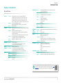 6
6
-
 7
7
-
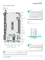 8
8
-
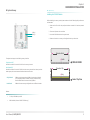 9
9
-
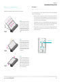 10
10
-
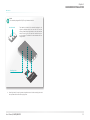 11
11
-
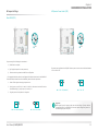 12
12
-
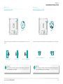 13
13
-
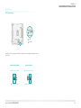 14
14
-
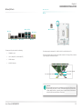 15
15
-
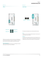 16
16
-
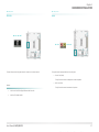 17
17
-
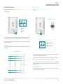 18
18
-
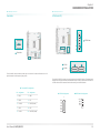 19
19
-
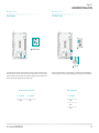 20
20
-
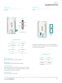 21
21
-
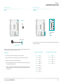 22
22
-
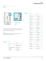 23
23
-
 24
24
-
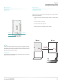 25
25
-
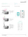 26
26
-
 27
27
-
 28
28
-
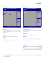 29
29
-
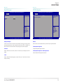 30
30
-
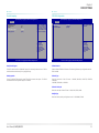 31
31
-
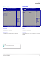 32
32
-
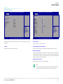 33
33
-
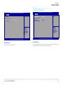 34
34
-
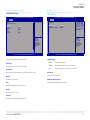 35
35
-
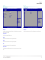 36
36
-
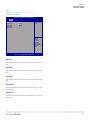 37
37
-
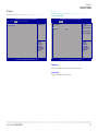 38
38
-
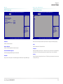 39
39
-
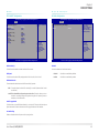 40
40
-
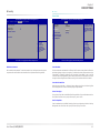 41
41
-
 42
42
-
 43
43
-
 44
44
-
 45
45
-
 46
46


DFI WL171/WL173 Owner's manual
- Category
- Motherboards
- Type
- Owner's manual
- This manual is also suitable for
Ask a question and I''ll find the answer in the document
Finding information in a document is now easier with AI
Related papers
-
DFI WL171/WL173 Owner's manual
-
-
-
-
DFI TGU171/TGU173 User manual
-
-
-
-
-
Other documents
-
Noctua NT-H1 User manual
-
 MSC 96M5980 User manual
-
 IBASE Technology ARRANDALE IB957 User manual
-
Supermicro X11SSN-H/-E/-L User manual
-
 IBASE Technology IB838 User manual
-
protech BE-0966 User manual
-
 Acrosser Technology AND-DNV3N2-04PC User manual
-
 Acrosser Technology AND-DNV3N2FL Owner's manual
-
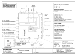 meitav-tec PS-1800-FC-SUPER Product information
-
Supermicro X11SWN-E User manual


