Page is loading ...

RS10420T
Installation Manual


The Robertshaw
®
Programmable WiFi Thermostat allows you to control the temperature
anytime and anywhere. It features a large backlit display and LCD touchscreen for ease
of operation. Compatible with any IOS or Android Smartphone.
Thermostat Application Guide
Power Type
Hardwire (Common Wire)
A trained, experienced technician
must install this product.
Carefully read these instructions. You
could damage this product or cause a
hazardous condition if you fail to follow
these instructions.
Description
Gas or Oil Heat Yes
Electric Furnace Yes
Heat Pump (No Aux. or Emergency
Heat)
Yes
Heat Pump (With Aux. or Emergency
Heat)
Yes
Multi-Stage Systems Yes
Heat Only Systems Yes
Cool Only Systems Yes
Millivolt Yes
INSTALLATION MANUAL
1

INSTALLATION TIPS
Table of Contents Page
Installation Tips 2-4
Thermostat Quick Reference 5
Wiring 6-8
Wiring Diagrams 9-11
Technician Setup 12-17
Programming 18-22
Thermostat Quick Reference 23
Setting Up WiFi Connection and App 24
Specications
Display range of temperature ..................................32°F to 99°F (0°C to 40°C)
Control range of temperature ..................................41°F to 90°F (5°C to 32°C)
Load rating .............................................................. 1 amp per terminal, 1.5 amp maximum all
terminals combined
Differential (cycle rate or swing) ............................. Heating is adjustable from 0.2° to 2.0°
Cooling is adjustable from 0.2° to 2.0°
Power source .......................................................... 18 to 30 VAC, NEC Class II, 50/60 Hz for
hardwire
Operating ambient temperature...............................32°F to +105°F (0°C to +41°C)
Operating humidity .................................................90% non-condensing maximum
Dimensions of thermostat ....................................... 4.7”W x 4.4”H x 1”D
2

Subbase Installation
Horizontal Mount
Vertical Mount
Installation Tip:
Electrical Hazard
Failure to disconnect the power
before beginning to install this
product can cause electrical shock
or equipment damage.
Mercury Notice
All of our products are mercury
free. However, if the product you
are replacing contains mercury,
dispose of it properly. Your local
waste management authority can
give you instructions on recycling
and proper disposal.
For vertical mount put one screw on
the top and one screw on the bottom.
For horizontal mount put one screw
on the left and one screw on the right.
1
1
1
2
2
2
INSTALLATION TIPS
3

Mount Thermostat
Align the 4 tabs on the subbase with
corresponding slots on the back of the
thermostat, then push gently until the
thermostat snaps in place.
WAKE
Heat
Menu
Auto
On
IAQ
Sun
Set At
FAN
SYSTEM
INSTALLATION TIPS
4

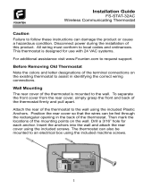
Getting to know your thermostat
Fan Buttons
Next Step Buttons
Set Time Buttons
Program Buttons
Menu Buttons
System Buttons
Setpoint Buttons
Days of the week and time
Indicates the current room temperature
Displays the user selectable
setpoint temperature
Hold is displayed when thermostat
program is permanently overridden.
System Operation Indicators: The
compressor delay is active if these are
ashing.
Programmable Time Periods:
Residential uses 4 time periods -
WAKE, RETURN, LEAVE and SLEEP.
Program Menu Options: Shows
different options during programming.
1
1
6
7
5
2
3
4
4
6
3
7
5
2
Sun Mon Tue Wed Thu Fri Sat
Sun Mon Tue Wed Thu Fri Sat
WAKE LEAVE RETURN SLEEP
WAKE LEAVE RETURN SLEEP
AM
PM
HOLD
Auto
On
IAQ
Technician
Setup
Next Step
Technician
Setup
Next Step
Set Time
Clean
Next Zone
Set Time
Clean
Next Zone
Set Schedule
Hold
Previous Step
Set Schedule
Hold
Previous Step
Run Schedule
Menu
Done
Run Schedule
Menu
Done
Heat Off
Cool
Auto
Em.heat
Heat Off
Cool
Auto
Em.heat
FAN
SYSTEM
SYSTEM
Set At
Set At
Auto
On
IAQ
HOLD
FAN
THERMOSTAT QUICK REFERENCE
5

Caution:
Electrical Hazard
Warning:
Installation Tip
Wiring
Max Torque = 6in/lbs.
Failure to disconnect the power before
beginning to install this product can
cause electrical shock or equipment
damage.
1.
2.
If you are replacing a thermostat, make
note of the terminal connections on the
thermostat that are being replaced. In
some cases the wiring connections will
not be color coded. For example, the
green wire may not be connected to the
G terminal.
Loosen the terminal block screws. Insert
wires then retighten the terminal block
screws.
Do not overtighten terminal
block screws, as this can
damage the terminal block.
A damaged terminal block can
keep the thermostat from tting
on the subbase correctly or
cause system operation issues.
All components of the control
system and the thermostat
installation must conform to
Class II circuits per the NEC Code.
WIRING
6

Terminal Designations
The following terminals on the thermostat wallplate are wired according
to the type of HVAC system it’s connected to and how the thermostat is
congured.
Devices, such as a oat switch that mechanically break circuits,
should be installed so that they break the control wire (Y) not the
power (R). Interrupting the power circuit will shut off the power to
the thermostat completely and not allow it to operate.
Note
CONVENTIONAL
HVAC
Y1
Y2 W/E W2
0 B
HEAT PUMP
COOL MODE
STAGE 1
HEAT 1
COOL 1
HEAT 2
COOL 2
HEAT 2
AUX 1
HEAT 3
AUX 2
HEAT 3
AUX 2
HEAT 2
AUX 2
HEAT PUMP
REVERSING
VALVE -
ENERGIZED
DURING
COOLING
HEAT PUMP
REVERSING
VALVE -
ENERGIZED
DURING
HEATING
HEAT 3
EMHEAT
HEAT 4
EMHEAT
AUX 1
AUX 1
HEAT 2
COOL 2
HEAT 2
COOL 2
1H / 1C
2H / 1C
3H / 1C
2H / 2C
3H / 2C
4H / 2C
COOL MODE
STAGE 2
HEAT MODE
STAGE 1
HEAT MODE
STAGE 2
–
–
WIRING
7

Wiring Tips
Wire Specications
Note:
Use shielded or non-shielded 18-22
gauge thermostat wire.
In many heat pump systems with
no emergency heat relay, a jumper
can be installed between E and
W2 to turn thermostat into a single
stage control for Emergency Heat
Operation.
WIRING
8

Power supply
Factory-installed jumper. Remove only when installing on 2-transformer
systems
Use either O or B terminals for reversing valve
24 VAC common connection
Typical 2H/2C System: 1 Transformer
COMPRESSOR
RELAY
COMPRESSOR
RELAY
COMPRESSOR
RELAY 2
HEAT RELAY
FAN RELAY
(HOT)
(HOT)
FAN RELAY
HEAT RELAY 2
Typical Cool-Only System With Fan
WIRING DIAGRAMS
9

Typical Heat Only System With Fan
In many systems with no emergency heat relay, a jumper can be
installed between E and W2.
Note:
FAN RELAY
HEAT RELAY
(HOT)
WIRING DIAGRAMS
10

Typical 3H/2C or 2H/1C Heat Pump System
Typical 2H/2C System: 2 Transformers
FAN RELAY
EMERGENCY
HEAT RELAY
COMPRESSOR
RELAY
COMPRESSOR
RELAY
FAN RELAY
HEAT RELAY
HEAT RELAY 2
COMPRESSOR
RELAY 2
REMOVE JUMPER
COMPRESSOR
RELAY 2
COOL REVERSING
VALVE
HEAT REVERSING
VALVE
AUXILIARY
HEAT RELAY
(HOT)
(HOT)
(HOT)
WIRING DIAGRAMS
11

1. Press MENU button
2. Press and hold TECHNICIAN SETUP button for 3 seconds. This 3 second delay is designed
so
that end users do not accidentally access the installer settings.
3. Congure
the installer options as desired using the table below.
4. Use the
–
or
+
keys to change settings and the
NEXT STEP or PREV
STEP key
to
move from
one step to another. Note: Only press DONE key when you want to exit the
Technician Setup options.
Tech Setup Steps
Setup WiFi
Filter Change
Reminder
OFF
Room
Temperature
Calibration
WiFi router parameter
configuration
This feature will flash a reminder
in the display after the elapsed run
time to remind the user to change
the filter. A setting of OFF will
disable this feature.
This feature allows the installer
to change the calibration of the
room temperature display. For
example, if the thermostat reads
70° degrees and you would like it
to read 72° then select +2.
You can adjust the room
temperature display to read
4° above or below the factory
calibrated reading.
You can adjust the filter change
reminder from OFF to 2000
hours of run time in 50 hour
increments.
LCD Will Show Adjustment Options Default
TECHNICIAN SETUP
12

Tech Setup Steps
LCD Will Show Adjustment Options Default
OFF
ON
0.5
Minimum
Compressor
On Time
Compressor
Short Cycle
Delay
Cooling
Differential
or Swing
This feature allows the Installer to
select the minimum run time for
the compressor. For example: A
setting of 4 will force the
compressor to run for at least 4
minutes every time the
compressor turns on, regardless of
the room temperature.
The compressor short cycle delay
protects the compressor from
short cycling. This feature will not
allow the compressor to be turned
on for 5 minutes after it was last
turned off.
The differential or swing
setting, often called cycle rate
or anticipation, is adjustable. A
smaller differential setting will
cause more frequent cycles and
a larger differential setting will
cause fewer cycles.
You can select the minimum
compressor run time from OFF,
3, 4, or 5 minutes. If 3, 4, or 5 is
selected, the compressor will
run for at least the selected time
before turning off.
Selecting ON will not allow
the compressor to be turned on
for 5 minutes after the last time
the compressor was switched
off. Select OFF to remove this
delay.
The cooling differential setting
is adjustable from 0.2° to 2°. For
example: A differential setting
of 0.5° will turn the cooling on
at approximately 0.5° above the
setpoint and turn the cooling off
at approximately 0.5° below the
setpoint.
TECHNICIAN SETUP
13

Tech Setup Steps
LCD Will Show
Heating
Differential
or Swing
Heat Pump
System Set
Stages of
Heat + Cool
The differential or swing
setting, often called cycle rate
or anticipation, is adjustable. A
smaller differential setting will
cause more frequent cycles and a
larger differential setting will cause
fewer cycles.
The heating differential setting
is adjustable from 0.2° to 2°. For
example: A differential setting
of 0.5° will turn the heating on
at approximately 0.5° below the
setpoint and turn the heating off
at approximately 0.5° above the
setpoint.
When turned on, the thermostat
will operate a heat pump. EM
Heat will show as an option in the
system switch tech setting.
Use the
+
and
–
button to
adjust.
You can configure the system
switch for the particular
application. Heat - Off - Cool,
Heat - Off, Cool - Off,
Heat - Off - Cool - Auto.
OFF configures the
thermostat for conventional
systems.
ON configures the
thermostat for heat pump
systems.
Use the
+
or
–
buttons
until the desired application
is flashing. AUTO = (Auto
Changeover)
SYSTEM
STAGES
Heat Off
Cool
Auto
Note: Emergency Heat is available
in heat pump mode only.
You can configure this thermostat
to operate up to 2H/2C
conventional, or up to 4H/2C
heat pump system.
Use the
+
or
–
key to
first select stages of heat,
press next, then select
stages of cool.
3 or 4 heat will use Y1 and Y2
as 1st and 2nd stage of heat.
This step is shown only if heat
pump is set to ON.
Adjustment Options Default
OFF
OFF
2
0.4
TECHNICIAN SETUP
14

Tech Setup Steps
LCD Will Show
Cooling Fan
Delay
Heating
Temperature
Setpoint
Limit
Cooling
Temperature
Setpoint
Limit
F° or C°
The cooling fan delay setting will
delay the fan from coming on in
cool mode and keep it running
after the compressor shuts off
for a short time to save energy in
some systems.
This feature allows you to set a
maximum heat setpoint value.
The setpoint temperature cannot
be raised above this value
This feature allows you to set a
minimum cool setpoint value.
The setpoint temperature cannot
be lowered below this value.
Select F for Fahrenheit readout
or select C for Celsius readout.
You can set the cooling fan
delay to OFF, 15, 30, 60 or
90 seconds. If 15, 30, 60, or
90 is selected the fan will not
turn on for that many seconds
when there is a call for cool
and will run for that many
seconds after satisfying a call
for cool.
Use the
–
or
+
key to select
the maximum heat setpoint.
Use the
–
or
+
key to select
the minimum cool setpoint.
Range 44°F - 90°F
Range 44°F - 90°F
F OR C SET
°F for Fahrenheit
°C for Celsius
Adjustment Options Default
90°
44°
F°
OFF
TECHNICIAN SETUP
15

Tech Setup Steps
LCD Will Show
12 or 24
Fan
Operation
Morning
Recovery
Display Light
Contractor
Call Number
12 Hour
Clock
You can select either 12 or 24
hour clock setting.
Select GAS for heating systems
that control the fan during a
call for heat.
GAS
or
ELEC
Select ELEC to have the
thermostat control the fan
during a call for heat.
This feature will start heating
early to bring the building
temperature to its programmed
setpoint by the beginning of the
WAKE time period.
The display light can be
configured to operate 2 different
ways – to come on when any
key is pressed or to stay on All
of the time.
Allows you to put your phone
number in the display. Selecting
ON will enable this feature. OFF
will disable this feature.
Use the
–
or
+
key to select
12 or 24 hour clock.
Use the
–
or
+
key to turn
on or off.
If selected On, you will see the
input screen after pressing next
step. Use the
+
or
–
keys
to select the desired number
and the FAN or SYSTEM key
to move from one character to
another. See Note on page 12 for
operation.
AUTO - Any key ON
ON - Always ON
Adjustment Options Default
GAS
ON
AUTO
OFF
TECHNICIAN SETUP
16

Tech Setup Steps
LCD Will Show
Beep
MACID
Firmware
Version
Factory
Default
Reset
ON
RESET
TO
When any key is pressed an
audible beep will sound. There is
an ON or an OFF.
This step shows the MAC address
of WiFi module.
This step shows the version of
firmware that is installed on the
thermostat.
This step resets all WiFi settings
to factory default.
If ON is selected the beep will
sound.
If OFF is selected, there is not
sound.
Press NEXT button to move to
next step. Press DONE button
to exit. Press and hold TECH
button to enter ADVANCED
TECH STEPS.
Press YES to reset.
Adjustment Options
Default
TECHNICIAN SETUP
17

Differential or Swing Setting Tip
The second stage will turn on at 2x the differential setting. The second stage
will turn off when 1x the differential is reached. For example, if the differential
setting is .5 degrees for heating and the thermostat is set at 70°F, the rst
stage will turn on at approximately 69.5°F. The second stage will turn on
at 69°F. The second stage will turn off at 69.5°F and the rst will turn off
at 70.5°F. If the third stage is used, it will turn on at 68.5°F and turn off at
approximately 69°F.
The function of activating your lockout choice takes place after you have
exited Tech Setup. To lock or unlock the keypad hold down the MENU for 3
seconds.
If contractor call number is selected ON, the respective phone number will
show in the display if there has been a continuous call for heating or cooling
for 24 hours or if the FAN button is held down for 3 seconds. To remove the
phone number from the display, hold the FAN button down for 3 seconds.
A Note About Keypad Lockout:
Contractor Call Number Note:
PROGRAMMING
18
/