Page is loading ...

RS8110
Installation Manual


Thermostat Applications Guide
This manual covers the following models: RS8110
Battery Power
Hardwire (Common Wire)
Hardwire (Common Wire) with Battery Backup
Description
Gas or Oil Heat Yes
Electric Furnace Yes
Heat Pump (No Aux. or Emergency Heat) Yes
Heat Pump (with Aux. or Emergency Heat) No
Multi-stage Systems No
Heat only Systems Yes
Heat only Systems - Floor or Wall Furnace Yes
Cool Only Systems Yes
Millivolt Yes
Table of Contents Page
Power Type
Installation Tips 2
Thermostat Quick Reference 3
Subbase Installation 4
Wiring 5-12
Technician Setup 13-14
Mounting and Battery Installation 15
Specications 16
A trained, experienced technician must install
this product.
Carefully read these instructions. You could damage
this product or cause a hazardous condition if you fail
to follow these instructions.
INSTALLATION MANUAL
1

Wall locations
Thethermostatshouldbeinstalledapproximately4to5feetabovetheoor.
Select an area with average temperature and good air circulation.
Do not install thermostat in locations:
• Close to hot or cold air ducts
• That are in direct sunlight
• With an outside wall behind the thermostat
• In areas that do not require heating and/or cooling
• Where there are dead spots or drafts (in corners or behind doors)
• Where there might be concealed chimneys or pipes
Tip
Pick an installation location that is easy for the user to access. The temperature of the location should be representative of the
building.
No
No No
Yes
INSTALLATION TIPS
2

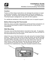
Getting to know your thermostat
a LCD Display
b Fan Switch
c System Switch
d Temperature Setpoint Buttons
e Easy change battery door
Displays the user selectable
setpoint temperature.
NOTE: The compressor delay
feature is active if these icons are
ashing.
The compressor will not turn
on until the 5 minute delay has
elapsed.
System operation indicators: The
COOL, HEAT or FAN icon will
display when the COOL, HEAT or
FAN is on.
Low Battery Indicator:
Replace batteries when
Indicator is shown.
a LCD
Indicates the current
room temperature.
Cool
HEAT
SYSTEM
FAN
AUTO
ON
Room
Set At
COOL
OFF
Room
Set At
THERMOSTAT QUICK REFERENCE
3

Caution:
Electrical Hazard
Failure to disconnect the power before
beginning to install this product can
cause electrical shock or equipment
damage.
For vertical mount put one
screw top and one screw
bottom.
For horizontal mount put
one screw left and one
screw right.
Mercury Notice:
All of our products are mercury free.
However, if the product you are replacing
contains mercury, dispose of it properly.
Your local waste management authority
can give you instructions on recycling and
proper disposal.
Vertical mount
Horizontal mount
Vertical mount
Horizontal mount
SUBBASE INSTALLATION
4

1 Turn Off Power to Heating/Cooling System
2 Remove Old Thermostat
Remove old thermostat but leave wallplate with wires attached.
Do not remove wallplate yet
Terminal
designation
Circuit breaker
box
Heating/cooling system
power switch
or
WIRING
5

Terminal designation
Wire Labels
3 Label Wires with Tags
Label the wires using the supplied wire labels as you disconnect them.
4 Separate Wallplate from New Thermostat
Remove wallplate from the new thermostat and mount onto wall.
Wiring Labels
Apply these wiring labels to each wire with the appropriate terminal
designation as you remove it from the existing thermostat.
B B Y2 Y2 C C E E F F
G G H H L L O O P P
R R RC RC RH RH T T U U
VNR VNR W W W1 W1 W2 W2 W3 W3
X X X1 X1 X2 X2 Y Y Y1 Y1
AUX AUX
Wallplate
ELEC
GAS
WIRING
6

Drill3/16-in.holesfordrywall
Drill3/16-in.holesforplaster
5 Separate Wallplate from New Thermostat
Mount the new wallplate using the included screws and anchors.
G
E
Y
RH/R
WIRING
7

6 Connect Wires
Simply match wire labels.
If labels do not match letters on the thermostat, check “Alternate Wiring (Conventional Systems)” on page 9
and connect to terminal as shown (see notes, below).
Remove metal jumper
if you have both R and
RC wires
Screw
Insert wires and tighten
screws
WIRING
8

Alternate Wiring (Conventional Systems)
If labels do not match letters on the thermostat, check the chart below and connect to terminal as shown here
(See notes, below).
1
Remove metal jumber if wires will be connected to both RH/R and RC terminals.
2
If a 24 volt common wire is present (typically labeled C or X) connect it to the C terminal. The C terminal is
not used if a 24 volt common wire is not present.
3
The O and B terminals are for a reversing valve (single stage heat pump application ONLY). These
terminals are not used on a system that is not a heat pump.
4
Place a jumper wire between the Y and W terminals if you have a single stage heat pump system ONLY.
WIRING
9

Wiring
1. If you are replacing a thermostat, make note
of the terminal connections on the thermostat
that is being replaced. In some cases the wiring
connections will not be color coded. For example,
the green wire may not be connected to the G
terminal.
2. Loosen the terminal block screws. Insert wires
then retighten terminal block screws.
Terminal Designations
W Heat relay G Fan relay Y Compressor relay
O Heat pump reversing valve energized in
cooling
RC 24 volt cooling transformer
RH/R 24 volt heating transformer OR 24 volt
power terminal if a common wire is present
B
Heat pump reversing valve energized in
heating
C
24 volt common terminal
Caution: Electrical Hazard
Failure to disconnect the power before
beginning to install this product can cause
electrical shock or equipment damage.
Warning:
All components of the control system and
the thermostat installation must conform to
Class II circuits per the NEC Code.
RH & RC terminals
For single transformer systems, leave the jumper
wire in place between RH and RC. Remove jumper
wire for two transformer systems.
Heat pump system (With No AUX or Emergency
Heat) If wiring to a heat pump, use a small piece of
wire (not supplied) to connect terminals W and Y.
Wirespecications
Use shielded or non-shielded 18-22 gauge thermo-
stat wire.
C terminal
The C (common wire) terminal does not have to
be connected when the thermostat is powered by
batteries.
Tips:
WIRING
10

1
Power supply.
2
Factory-Installed jumper. Remove only when installing on 2-transformer systems.
3
Use either O or B terminals for reversing valve. Heat pump application ONLY.
4
Use a small piece of wire (not supplied) to connect W and Y terminals.
5
Set fan operation switch to either gas or electric based on your system.
6
Optional 24 VAC common connection not to be used when powering thermostat with batteries.
Typical 1H/1C system: 1 transformer
REMOVE JUMPER
C0MPRESSOR
RELAY
FAN RELAY
L1 (HOT)
L2
HEAT RELAY
Typical 1H/1C system: 2 transformer
L1 (HOT)
L2
L1 (HOT)
L2
C0MPRESSOR
RELAY
FAN RELAY
HEAT RELAY
WIRING
11

Typical heat-only system with fan
Typical 1H/1C heat pump system
Typical cool-only system
Typical heat-only system
L1 (HOT)
L2
24 V common wire may not be present in all systems.
COMPRESSOR
RELAY
HEAT REVERSING
VALV E
COOL REVERSING
VALV E
COMPRESSOR
RELAY
FAN RELAY
FAN RELAY
HEAT RELAY
FAN RELAY
L1 (HOT)
L1 (HOT)
L2
L2
L1 (HOT)
L2
HEAT RELAY
Tips:
WIRING
12

Gas or Electric Setup
Gas: For systems that control the fan during a
call for heat, put the fan operation switch to the
GAS position.
Electric: The thermostat operation switch should
be put in the ELEC position. This setting allows
the thermostat to operate the fan when the fan
relay is connected to the G terminal.
Select ELEC or GAS
with this switch
TECHNICIAN SETUP
13

Adjusting the Differential (Also called
Swing or Cycle rate)
The differential is adjustable, a smaller
differential will cause more frequent
cycles and a larger differential will
cause fewer cycles. There are separate
differentials for heat and for cool. Follow
the steps below to adjust the differential
for heat or cool:
1.
Select HEAT or COOL with the system
switch.
2. Hold down the
+
and
-
keys
together for 3 seconds.
3.
Use the
+
or
-
key to adjust
the differential. The differential is
adjustable from ±0.2°F to ±2°F.
For example: A differential setting
of 0.5°F will turn the cooling on
at approximately 0.5°F above the
setpoint and turn the cooling off
at approximately 0.5°F below the
setpoint. The factory default for cooling
is 0.5°F and 0.4°F for heating.
4. Wait approximately 10 seconds for
the thermostat to return to normal
operation.
This feature allows the Installer to
change the calibration of the room
temperature display. For example: If the
thermostat reads 70° and you would like
it to read 72° then select +2. You can
adjust the room temperature display to
read -4°F to +4°F above or below the
factory calibrated reading. Follow the
steps below to adjust the temperature
reading:
1. Select OFF with the system switch.
2. Hold down the
+
and
-
keys
together for 3 seconds.
3. Use the
+
key to adjust the room
temperature display.
4. Then press
-
to access the F
(Fahrenheit) or C (Celsius) setting.
use
+
to select.
5. Press
-
again to access the
compressor DELAY selection. The
compressor delay will not allow
the compressor to be turned on for
5 minutes after the last time the
compressor was shutdown. Use
the
+
to select ON or OFF. (ON
will prevent the compressor from
starting for at least 3 minutes). Wait
approximately 15 seconds or slide
the system switch to return to normal
operation.
Adjusting Room Temperature Calibration, Fahrenheit/Celcius Display and
Compressor Delay
TECHNICIAN SETUP
14

Mount Thermostat
Align the 4 tabs on the subbase with corresponding slots
on the back of the thermostat, then push gently until the
thermostat snaps in place.
Battery Installation
Battery Installation is optional if thermostat is hardwired (C terminal connected).
1.5 V AAA1.5 V AAA
Insert 2 AAA Alkaline batteries
(included).
Cool
HEAT
SYSTEM
FAN
AUTO
ON
Room
Set At
COOL
MOUNTING & BATTERY INSTALLATION
15

The display range of temperature.......41°F to 95°F (5°C to 35°C)
The control range of temperature .......44°F to 90°F (7°C to 32°C)
Load rating..........................................1 amp per terminal, 1.5 amp maximum all terminals combined
Display accuracy ................................± 1°F
Swing (cycle rate or differential) .........Heating is adjustable from 0.2°F to 2.0°F
Cooling is adjustable from 0.2°F to 2.0°F
Power source......................................18to30VAC,NECClassII,50/60Hzforhardwire(commonwire)
Battery power from 2 AAA Alkaline batteries
Operating ambient temperature..........32°F to +105°F (0°C to +41°C)
Operating humidity .............................90% non-condensing maximum
Dimensions of thermostat ...................4.72”W x 3.80”H x 0.98”D
SPECIFICATIONS
16


Customer Service +1.800.304.6563
Technical Service +1.800.445.8299
HVACCustomerService@robertshaw.com
www.robertshaw.com • 352-00301-001
6
Year
Limited
Warranty
Use Phone
to Scan for
Warranty Info
/