- 4 - - 5 -
Checking and Replenishing Tank Air Charge
Supercell ‘P’, ‘G’, ‘PHP16’ and ‘HP25’ Pressure Tanks do not require regular
checks under normal operating conditions. However, if air charge adjustment is
required then follow the following procedures:
1. Remove the pressure tank completely from pump installation, ensuring
to isolate the pressure tank and release the water pressure from the tank
beforehand. OR
Release all water pressure from the pressure tank by switching off the pump
at the power point, and opening the closet tap. For above ground supply
tanks it is necessary to close the gate valve between the supply tank and
the pump.
Leave tap open during air replenishment.
2. When all water pressure has been released from the system, check air
pressure at air valve on top of pressure tank. The pre-charge pressure
reading should be as detailed on page 3 of this document.
3. If necessary, replenish air charge to the correct pressure indicated. Ensure that
a tap in outlet piping of pump is open during replenishment of air pre-charge.
Periodic Checks
Flushing: Depending on the quality of the pumped water, from time to time your
tank may require ushing to remove settled nes such as mud or sand. If sand
or mud is allowed to stay in the tank it will accelerate wear on the internal lining
and shorten your tanks life.
Safely disconnect the tank from the water supply, discharge all air from the tank
and ush the tank several times with clean water. Once the ushing water is
clean, reconnect the tank and recharge the air as per above.
External Inspection: A tank in good order will not leak, but over time due to
damage through rough handling, impacts or grit and/or impurities in the water
the tank shell may fail and/or leak. Should the tank leak or show signs of
possible failure the tank should be immediately disconnected and replaced.
CAUTION: To prevent personal injury, ensure all water pressure is
released from the pressure system prior to work being performed.
NOTE: During air replenishment the tank should be externally
inspected. Any signs of leakage from the tank may indicate a need for
immediate replacement.
WARNING: Do not use tank if it leaks or shows signs of corrosion
or damage.
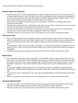
Operational Difculties & Trouble Shooting
NOTE: Loss of air charge is the most overwhelming cause of difculties with
Supercell Pressure Tanks. Partial or complete loss of air charge will
cause any of the following problems:-
a) Rapid pump cycling (i.e. pump stops and starts frequently during
operation).
b) Decreased draw-off capacity.
Alternatively, the same problems could be caused by a punctured or
leaking diaphragm as indicated by water leaking from the air valve
when the valve core is depressed (typically when checking tank pre-
charge).
Supercell Sufx ‘P’, ‘G’, ‘PHP16’ and ‘HP25’ models have a
diaphragm which is captive and is non-serviceable. In the event of
diaphragm failure the whole tank must be replaced.
Symptom Causes Remedies
Pump Cycling i) Punctured diaphragm (check that water i) Replace Tank.
(Pump stops and starts escapes from air valve when depressed)
frequently while operating) ii) Incorrectly set pressure switch ii) Reset pressure switch to manufacturers
recommendations
iii) Incorrect pressure tank pre-charge iii) Adjust tank pre-charge to 15kPa (2psi)
below cut-in
Pump stops and starts i) Leaking tap or pipework on suction i) Isolate suction pipework, if pump
when all taps are closed and/or discharge side continues to stop and start, check for
leaks on discharge. If pump stops and
does not restart, problem is likely to be
leaking checkvalve on suction side of
pump system.
Water ow from open tap i) Tank pre-charge set too high or too low i) Adjust tank pre-charge to 15kPa (2psi)
stops then starts when rst ii) Pressure switch cut-in set too low below cut-in
opened ii) Adjust pressure switch cut-in
Tank will not hold air i) Faulty air valve i) Replace air valve core
pre-charge ii) Punctured diaphragm
48995-14_Supercell_P_G_PHP16_RHP25.indd 4 16/03/2017 3:15 PM