Page is loading ...

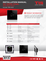
This product features a bell panel with room
number display and touch buttons for room
services designed for maximum conveniene and
efciency in hospitality facilities.
PRODUCT INFORMATION
BARCODE (UPC-A)
6 58921 80014 0
PRODUCT SPECIFICATIONS
Input RF card reader (RF Type) Temic RF Type
Dry inputs 4 Digital Inputs
Output Low current relay 1 Relay Output 2A/12V
TIS Bus``
Number of devices on 1 line Max. 64
Bus voltage 12-32 V DC
Current consumption <25 mA / 24 V DC
Protection Reverse polarity protection
ESD protection
Operation
Push buttons 1 Push button with Red / White Indicator…
Backlight 2 RGB indicators + Room number white LEDs
TIS bus TIS Protocol messages and commands
Upgrading By Rs485 upgrading kit.
Functions Bell Press Push button
Dimensions Width × Length × Height 94mm× 13mm × 129mm
Housing
Materials Fireproof PC / acrylic in front
Casing color Silver plating frame. Glass black
Internal parts color Black & White
IP rating IP 50
INSTALLATION MANUAL
TIS IO OUTDOOR BELL PANEL
MODEL: IO-OUT-HOTEL, IO-OUT-HOTEL-RF

INSTALLATION MANUAL
MODEL: IO-OUT-HOTEL, IO-OUT-HOTEL-RF
TIS IO OUTDOOR BELL PANEL
2
www.tiscontrol.com
TIS CONTROL LIMITED
Wanchai, Hong Kong
TIS CONTROL PTY LIMITED
SA , AUSTRALIA
Copyright © 2022 TIS, All Rights Reserved
TIS Logo is registered trademark of TIS CONTROL.
All of the specification are subject to change without notice.
Mounting Location
Install in a dry, indoor area with a suitable
temperature and humidity range.
Data Cable
Use screened stranded RS485 data cable
with four twisted pairs. Congure devices
in a “Daisy Chain.”
Do not cut or terminate live data cables.
Warranty
There is a two-year warranty provided
by law. The hologram warranty seal and
product serial number are available on
each device.
Read Instructions
We recommend that you read this
Instruction Manual before installation.
Safety instructions
Electrical equipment should only be
installed and tted by electrically skilled
persons.
Failure to follow the instructions may
cause damage to the device and other
hazards.
These instructions are an integral part of
the product and must remain with the end
customer.
Programming
Advanced programming requires
knowledge of the TIS Device Search
software and instruction in the TIS
advanced training courses.
Simple Installation
You can use 2 screws to install this panel
on wall; it ts on most junction box sizes.

INSTALLATION MANUAL
MODEL: IO-OUT-HOTEL, IO-OUT-HOTEL-RF
TIS IO OUTDOOR BELL PANEL
3
www.tiscontrol.com
TIS CONTROL LIMITED
Wanchai, Hong Kong
TIS CONTROL PTY LIMITED
SA , AUSTRALIA
Copyright © 2022 TIS, All Rights Reserved
TIS Logo is registered trademark of TIS CONTROL.
All of the specification are subject to change without notice.
Insert a large athead screwdriver in
the hole of the Panel Cover. Rotate the
screwdriver 90 degrees.
1
INSTALLATION STEPS
2Separate the Main Panel and Wall Base
from each other.

INSTALLATION MANUAL
MODEL: IO-OUT-HOTEL, IO-OUT-HOTEL-RF
TIS IO OUTDOOR BELL PANEL
4
www.tiscontrol.com
TIS CONTROL LIMITED
Wanchai, Hong Kong
TIS CONTROL PTY LIMITED
SA , AUSTRALIA
Copyright © 2022 TIS, All Rights Reserved
TIS Logo is registered trademark of TIS CONTROL.
All of the specification are subject to change without notice.
INSTALLATION STEPS
3
4
5
Turn off the main electrical source before
installation.
Connect the Cat5e TIS BUS wire to the
Panel.
Connect the other connection if needed
between wall services switches to the
digital inputs of the hotel panel as per the
following diagram.
IO OUTDOOR PANEL
Model: IO-OUT-HOTEL-RF
www.tissmarthome.com
R7 R8
C2
VD4
L1
089
E3 Q4 C20 C26
DND CLEAN LUNDARY CARD GND RIN ROUT
R1
C1 E1
R3
VD6
E2
F3
D3
N1
+24V D+ D- GND
C4
Q1
VD1
F1
F2
R2
ac
ac
REMOVE
AFTER
WASHING
HF04
227A
ac
GND(white-orange)&(white-brown)
D-(white-green)&(white-blue)
Cat5e connection
+24V(brown-orange)
D+(blue-green)
Cat5e
to the TIS BUS Network
IO-OUT-HOTEL-RF
IO OUTDOOR PANEL
Model: IO-OUT-HOTEL-RF
www.tissmarthome.com
R7 R8
C2
VD4
L1
089
E3 Q4 C20 C26
DND CLEAN LUNDARY CARD GND RIN ROUT
R1
C1 E1
R3
VD6
E2
F3
D3
N1
+24V D+ D- GND
C4
Q1
VD1
F1
F2
R2
ac
ac
REMOVE
AFTER
WASHING
HF04
227A
ac
Cat5e to the TIS BUS Network
L
S
S
L
L1
S1
S1
S2
L2
L1
S2
L2
PLEASE
DISTURB
DO NOT
WASH LAUNDRY MAKEUP ROOM
D-(white-green)&(white-blue)
D+(blue-green)
+24V(brown-orange)
Cate5e connection
low volage cable
low volage cable
GND(white-orange)&(white-brown)
WARNING! HIGH VOLTAGE

INSTALLATION MANUAL
MODEL: IO-OUT-HOTEL, IO-OUT-HOTEL-RF
TIS IO OUTDOOR BELL PANEL
5
www.tiscontrol.com
TIS CONTROL LIMITED
Wanchai, Hong Kong
TIS CONTROL PTY LIMITED
SA , AUSTRALIA
Copyright © 2022 TIS, All Rights Reserved
TIS Logo is registered trademark of TIS CONTROL.
All of the specification are subject to change without notice.
INSTALLATION STEPS
6
7
Connect the Door Bell to the Relay if it
exists in the room.
If you want to connect electrical lock to
the RF Hotel panel type please connect it
as per this diagram.
IO OUTDOOR PANEL
Model: IO-OUT-HOTEL-RF
www.tissmarthome.com
R7 R8
C2
VD4
L1
089
E3 Q4 C20 C26
DND CLEAN LUNDARY CARD GND RIN ROUT
R1
C1 E1
R3
VD6
E2
F3
D3
N1
+24V D+ D- GND
C4
Q1
VD1
F1
F2
R2
ac
ac
REMOVE
AFTER
WASHING
HF04
227A
ac
GND(white-orange)&(white-brown)
D-(white-green)&(white-blue)
Cat5e connection
+24V(brown-orange)
D+(blue-green)
1.5 mm Electric Cable
1.5 mm Electric Cable
low voltage cable
low voltage cable
Door Bell
Connect To L
Connect To N
Cat5e to the TIS BUS Network
IO-OUT-HOTEL-RF
AC/DC ADAPTER
Input 110~220V AC
Output 12V DC
IO OUTDOOR PANEL
Model:
www.tissmarthome.com
R7 R8
C2
VD4
L1
089
E3 Q4 C20 C26
DND CLEAN LUNDARY CARD GND RIN ROUT
R1
C1 E1
R3
VD6
E2
F3
D3
N1
+24V D+ D- GND
C4
Q1
VD1
F1
F2
R2
ac
ac
REMOVE
AFTER
WASHING
HF04
227A
ac
GND(white-orange)&(white-brown)
D-(white-green)&(white-blue)
Cat5
e connection
+24V(brown-orange)
D+(blue-green)
1.5 mm Electric Cable
1.5 mm Electric Cable
low voltage cable
low voltage cable
Electric Lock
Connect To L
Connect To N
Cat5e
to the TIS BUS Network
IO-OUT-HOTEL-RF
AC/DC ADAPTER
Input 110~220V AC
Output 12V DC

INSTALLATION MANUAL
MODEL: IO-OUT-HOTEL, IO-OUT-HOTEL-RF
TIS IO OUTDOOR BELL PANEL
6
www.tiscontrol.com
TIS CONTROL LIMITED
Wanchai, Hong Kong
TIS CONTROL PTY LIMITED
SA , AUSTRALIA
Copyright © 2022 TIS, All Rights Reserved
TIS Logo is registered trademark of TIS CONTROL.
All of the specification are subject to change without notice.
INSTALLATION STEPS
8
9
Mount the wall base on the wall using 2
screws on the junction box.
Connect the main IO panel vertically to
the part installed on the wall; install the
upper part by making sure the buckles
are completely inside.

INSTALLATION MANUAL
MODEL: IO-OUT-HOTEL, IO-OUT-HOTEL-RF
TIS IO OUTDOOR BELL PANEL
7
www.tiscontrol.com
TIS CONTROL LIMITED
Wanchai, Hong Kong
TIS CONTROL PTY LIMITED
SA , AUSTRALIA
Copyright © 2022 TIS, All Rights Reserved
TIS Logo is registered trademark of TIS CONTROL.
All of the specification are subject to change without notice.
11 Turn on the power source. The panel
should turn ON.
10 Apply pressure to the bottom part of
the panel to x it to the wall base and
complete the assembly.

INSTALLATION MANUAL
MODEL: IO-OUT-HOTEL, IO-OUT-HOTEL-RF
TIS IO OUTDOOR BELL PANEL
8
www.tiscontrol.com
TIS CONTROL LIMITED
Wanchai, Hong Kong
TIS CONTROL PTY LIMITED
SA , AUSTRALIA
Copyright © 2022 TIS, All Rights Reserved
TIS Logo is registered trademark of TIS CONTROL.
All of the specification are subject to change without notice.
USER OPERATIONS
This panel features 3 hotel service
indicators including Laundry, Make Up
Room, & Do Not Disturb (DND).
Once a service is selected by a guest using
the indoor unit, the LED backlit icon of the
requested service turns ON on the outside
panel.
Please note that the LED backlit color is
customizable via the TIS Software
If you are using the panel with RF access
control function, hold the card near the
reader position on the panel to open doors.
SERVICE INDICATION & BELL PRESS
RF ACCESS CONTROL
BACKLIT COLOR INDICATION
White Room is occupied & DND is OFF. You can press the bell, and it will
ring inside the room if the bell is connected.
Red DND mode is ON & bell function is disabled.
OFF
(No backlight) Room is vacant. Room service is provided rst thing in the morning.
The bell button backlit colors indicate the following:

INSTALLATION MANUAL
MODEL: IO-OUT-HOTEL, IO-OUT-HOTEL-RF
TIS IO OUTDOOR BELL PANEL
9
www.tiscontrol.com
TIS CONTROL LIMITED
Wanchai, Hong Kong
TIS CONTROL PTY LIMITED
SA , AUSTRALIA
Copyright © 2022 TIS, All Rights Reserved
TIS Logo is registered trademark of TIS CONTROL.
All of the specification are subject to change without notice.
TROUBLESHOOTING
The panel buttons’ LEDs do
not turn ON, and the device
is not powered
Reason: The TIS 24V power supply is not
connected to the TIS-BUS.
The wall panels fail to
communicate with other
devices
Reason: The TIS-BUS connection has a
problem, or the wire has a short.
Service LED is not turning
ON/OFF
Reason 1: When programming, you did not set
the right message or address.
Reason 2: ON status color is set to black in the
software.
/