Page is loading ...

Ceiling Exhaust Fan with Light (Non-ducted)
Cat. No: EFND620WE (Adaptable Light)
EFND620LEDWE (Integrated LED Panel)
Instruction Sheet
1
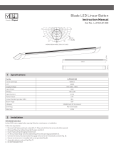
1. Determine the position in ceiling
where fanlight is required to be
installed. (Do not install within
120cm of stove or inside a shower
recess). Be certain that the
installation area is not restricted
by roof beams above a ceiling
refer table for clearance required.
5. ■ Unclip 2 x reflector clips and
let the assembly hang by the
hinge as in Fig 5.
■ Fold the toggles in (Fig.6(a)).
■ Unscrew the 3 screws on the
lip of the unit until the gap
between the toggles and
inner lip of the unit is greater
than thickness of the Gyprock,
or other ceiling material.
■ Ensure there is ample clearance
in the ceiling space for the
draft-stopper to function, see
the specification table in
section 3.
Current New Zealand Building regulations prohibit the use of non-ducted fans for new installations. If you are replacing an existing fan and a non-ducted
fan was originally installed, that was compliant with regulations at the time of installation; it can be replaced with the same type of non-ducted fan. A
licensed electrician is required to connect this unit to the mains supply. A lamp (E27 LED 10W Max.) is required for the EFND620WE model (not supplied).
8. It is recommended that the
three toggles are checked
for the correct clamping by
inspection from above see
Fig.8.
10. Ensure the diffuser is fixed firmly
by locating the latches and
turning clockwise.
9. To install E27 LED globe, release
the diffuser by holding firmly and
rotating anti-clockwise. Insert
lamp as shown in Fig.9
2. Use the template provided
to draw a circle 300mm in
diameter. To do this insert a
thumb tack in hole at one end
and insert a pencil in the other
hole and scribe a circle.
3. Use an electric jig saw or small
hand saw to cut out around this
line. Several holes drilled at a
point inside the circle provides
a convenient starting point for
cutting the panel out.
4. Remove the terminal cover and
wire according to the diagrams
in section 2.
Variable field of view
6 Product Notes
Warranty
Legrand warrants this product for a period of 5 years from the date
of purchase. These goods come with guarantees that cannot be
excluded under the Australian and New Zealand Consumer Laws.
You are entitled to a replacement or a refund for a major failure
and for compensation for any other reasonably foreseeable loss
or damage. You are also entitled to have the goods repaired if the
goods fail to be acceptable quality and the failure does not amount
to a major failure.
See the Warranty card enclosed with this product for further details.
Customer Service
For all Customer Service and Technical Support
please call Monday to Friday during business hours.
Legrand Australia
1300 369 777
www.hpm.com.au
Legrand New Zealand
0800 476 009
www.hpm.co.nz
ABN: 31 000 102 661
LE13263AA 02/2022
1. This product must be installed and used as per these instructions.
For indoor ceiling mount applications only.
2. This fan is not suitable for use with after-market ducting kits.
3. All wiring must be carried out by a licensed electrician.
4. Means for disconnection must be incorporated in the fixed wiring in
accordance with the Wiring Rules.
5. This product should only be cleaned with a damp cloth. Cleaning
agents and solvents should not be used.
6. Ensure the fan is switched off from the mains supply before removing
the grill and diffuser for cleaning purposes.
7. This appliance is intended for household use and similar purposes.
It is not suitable for use in an environment heavily laden with dust.
Under these conditions, the life of the fan motor can be significantly
reduced.
8. The fan is to be installed in a ceiling at least 2.3m above floor level.
9. This appliance is not intended for use by young persons (including
children) with reduced physical, sensory or mental capabilities,
or lack of experience and knowledge, unless they have been given
supervision or instruction concerning the use of the appliance by a
person responsible for their safety. Children should be supervised to
ensure that they do not play with the appliance.
10. Airflows listed in this product indicate the product performance.
Refer to the BCA (Building Code of Australia), or similar, for the
appropriate number of room air changes/extraction rate required for
a particular installation.
11. Ensure the fan is switched OFF from the mains supply before
removing fascia for cleaning purposes.
12. Ventilation products must have an adequate source of external air to
ensure rated performance can be achieved.
13. This product contains no serviceable parts and no attempt should
be made to repair this product. If the product is faulty it should be
discarded.
14. Severe electromagnetic interference from other products may cause
malfunction of this product.
15. The material in this product may vary in colour from batch to batch.
Colour matching from one batch to another cannot be guaranteed.
16. Electrical installations periodically receive transient over-voltages.
This product has been designed to minimise the effect of such
voltages on connected equipment. It may not give full protection for
extreme over voltage transients such as those resulting from a close
lightning strike.
17. Exhaust fans may adversely affect the safe operation of appliances
burning gas or other fuels (including those from other rooms) due to
back flow of combustion gases. These gases can potentially result
in carbon monoxide poisoning. After installation of an exhaust fan
such as a partition fan, the operation of flued gas appliance should be
tested by a competent person to ensure that back flow of combustion
gases does not occur.
18. This product utilises intellectual property in the form of registered
designs, trademarks, and/or patents. Such intellectual property
remains the property of Legrand in all cases.
19. Legrand reserves the right to modify the specifications of this product
at any time.
Paper
Installation
Toggles
Fig.1 Fig.2 Fig.4
Fig.3
Fig.5
Fig.7
7. Locate clips gently before
pressing the assembly in
to avoid damage (See fig .7).
Fig.9
Fig.8 Fig.10
6. ■ Push the unit into the ceiling.
■ Use your fingers to close the
toggle clamp (Fig.6(b)).
■ Tighten the retention screws
clockwise until it is firm and
stable allowing the toggles to
grip the ceiling material as in
Fig.8.
Toggle Clamp open
Fig.6 (a)
Toggle Clamp closed
Ø330 mm
60 mm
230 mm
171 mm
For EFND620WE only
Fig.6 (b)
Hinge Clips
CLICKCLICK

Variable field of view
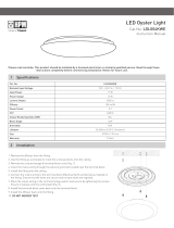
2 Switching Arrangements
INSTALLATION/APPLICATION
Terminal block
& cover Motor
housing
Reector
Dust seal
Retention
screws
Lampholder
Fan blade
Fan intake
grille
Light diuser
Option 1: Fan and light switched together
Option 2: Fan and light switched separately
Option 3: Fan and light switched together with time
delay on fan after switch is turned off
Fan/Light switch
Fan switch
Light switch
1
1 2
C
Fan/Light Switch
HPM Cat. TX770/1RC
to light to fan
1 2
C
1
2
C
2
C
N L
FAN
A
A
LOOP
NEUTRAL
LIGHT
FAN
A
A
LOOP
NEUTRAL
LIGHT
FAN
A
A
LOOP
NEUTRAL
LIGHT
N L
N L
Double pole
disconnection switch
or 2 pin plug
Double pole
disconnection
switch or 2 pin
plug
Double pole
disconnection switch
or 2 pin plug
Variable field of view
3
4
5
Specifications
Maintenance
Box Contents
EFND620WE EFND620LEDWE
Nominal Input Voltage 230 - 240 V a.c. 50 Hz
Maximum Power Consumption 27 W (Max) 28 W (Max)
Class of Protection Class II
LIGHT
Lampholder E27 N/A
Consumption Max.10 W LED Only (Lamp not supplied) 11 W (Integrated LED Panel)
Lumen output N/A 1190 lm
CCT N/A 4000k (Cool White)
Dimming N/A Non-Dimmable
FAN
Consumption 17 W (Max)
Airflow 260 m3/hr, 72 l/sec
Sound pressure level (dBA) at 3m 46 dBA
Ceiling Cut-out Size 300 mm
Protrusion from Ceiling 60 mm
Projection into Ceiling 230 mm (Max)
Ceiling Depth (Required) 250 mm (Min)
Impeller Diameter 210 mm
Fascia size 330 mm
Weight (Normal) 2.25 kgs
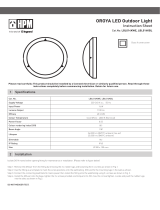
Lamp Holder Version
EFND620WE (Adaptable Light) EFND620LEDWE (Integrated LED Panel)
■ Hold on to the “Lamp Unit” on opposite side of Hinge
as shown and pull down firmly to release the Lamp
Unit for cleaning. After cleaning assemble the
Reflector unit by locating the 2 x Latches in the clips
and push up gently until you hear a “Click” .
To remove diffuser for cleaning,
1. Ensure the fan is switched OFF from the mains supply before removing
diffuser for cleaning purposes.
2. This product should only be cleaned with a damp cloth. Cleaning agents and
solvents should not be used.
3. Hold diffuser firmly and rotate anti-clockwise and then pull down.
4. Locate the 3 x latches and turn clock-wise until you hear a click. Ensure all 3
clips are assembled before turning.
■ Failure to secure the diffuser firmly as outlined above may result in injury.
■ 1 x Exhaust Fan with draft stopper ■ Instructionsheet
■ Cut-out template ■ Warranty Card
Lamp unit
Clips
Hinge
Diffuser
Diffuser
Diffuser
Note: Do not remove Lamp Unit from Hinge.
Ensure the fan is switched OFF from the mains supply
before maintenance.
/