Page is loading ...

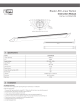
Fan Light - Ceiling Exhaust
Fan and Light
Cat. R620
Instruction Information
1 Installation
1. Determine position in ceiling
where Fanlight is required to
be installed. (Do not install
within 120cm of stove or inside
a shower recess). Be certain
that the installation area is not
restricted by roof beams above
ceiling.
5. Remove light diffuser and
air-intake grille. Unscrew
the 3 screws on the lip of the
unit until the gap between the
toggles and inner lip of the
unit is greater than the width
of the Gyprock, or other ceiling
material. Fold these toggles in.
Push unit into hole.
A licensed electrician is required to connect this unit to the mains supply.
6. Turn the retention screws
clockwise. The toggles will splay
out. Tightening the retention
screws allows the toggles to
grip the ceiling material.
7. It is recommended that the
three toggles be checked for the
correct clamping by inspection
from above.
8. You may now insert a globe
(not more than 75W) into the
lampholder. Push grille into
unit and click into position.
Assemble the diffuser and round
dust seal and twist into position.
To remove this assembly for
cleaning, simply pull assembly
downwards. For globe changing
only, simply twist the diffuser
anticlockwise and remove.
2. Use template provided to draw
a circle 300mm in diameter.
To do this insert a thumb tack
in hole at one end and insert
a pencil in the other hole and
scribe a circle.
3. Use electric jig saw or small
hand saw to cut out around this
line. Several holes drilled at a
point inside the circle provides
a convenient starting point for
cutting the panel out.
4. Remove terminal cover and
wire according to the diagram
in Option 1 over. This method of
wiring switches fan and light on
and off simultaneously. Option
2 shows how to wire fan and
light separately. This allows the
light (or the fan) to be switched
on independently of the other.
Option 3 shows the addition of a
HPM Cat TX770/1RC time delay
mechanism.

Variable field of view
23
4
5
Switching arrangements Specifications
Product parts
Warning
Supply voltage: 240V a.c. 50Hz
Maximum Power
Consumption: 113W
Lamp: 75W (Max)
Fan: 38W
Ceiling cut-out: 300mm
Protrusion from ceiling: 90mm
Projection into ceiling: 130mm
Impeller diameter: 200mm
Weight (Normal): 3.0kg
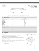
INSTALLATION/APPLICATION
Terminal block
& cover Motor
housing
Reflector
Dust seal
Retention
screws
Lampholder
Fan blade
Fan intake
grille
Light diffuser
Option 1: Fan and light switched together
Option 2: Fan and light switched seperately
Option 3: Fan and light switched together with time
delay on fan after switch is turned off
Fan/Light switch
Fan switch
Light switch
1
1 2
C
Fan/Light Switch
HPM Cat. TX770/1RC
to light to fan
1 2
C
1
2
C
2
C
N L
FAN
A
A
LOOP
NEUTRAL
LIGHT
FAN
A
A
LOOP
NEUTRAL
LIGHT
FAN
A
A
LOOP
NEUTRAL
LIGHT
N L
N L
K: Double pole
disconnection
switch or 2 pin plug
K: Double pole
disconnection
switch or 2 pin
plug
K: Double pole
disconnection
switch or 2 pin plug
Warranty
HPM Legrand will honour all statutory guarantees that you as a consumer are entitled to
rely upon under the Australian Consumer Law against a manufacturer including a guarantee
that products are of acceptable quality. To make a claim under any statutory guarantee (or
other warranty) you should first contact the supplier, contractor or retailer from whom you
purchased the products.
Customer Service
For all Customer Service and Technical Support
please call Monday to Friday during business hours.
HPM Legrand Australia
1300 369 777
www.hpmlegrand.com.au
HPM Legrand New Zealand
0800 476 009
www.hpmlegrand.co.nz
ABN: 31 000 102 661
LE05800ADA
WARNING:
Ensure the fan is switched off from mains supply before removing grille
and diffuser for cleaning purposes.
Means for disconnection must be incorporated in the fixed wiring in
accordance with the wiring rules.
This appliance is not intended for use by persons (including children)
with reduced physical, sensory or mental capabilities, or lack of
experience and knowledge, unless they have been given supervision or
instruction concerning use of the appliance by a person responsible for
their safety.
Children should be supervised to ensure that they do not play with the
appliance.
/