NDS Radiance G2 32" Owner's manual
- Category
- TVs & monitors
- Type
- Owner's manual

Radiance® G2 32"
USER MANUAL
ENGLISH


© 2017 NDS Surgical Imaging, LLC. All rights reserved.
Information in this document has been carefully checked for accuracy; however, no guarantee is given to the
correctness of the contents. This document is subject to change without notice. NDS provides this information as
reference only. Reference to products from other vendors does not imply any recommendation or endorsement.
This document contains proprietary information protected by copyright. No part of this manual may be
reproduced by any mechanical, electronic, or other means, in any form, without prior written permission of NDS.
All trademarks are the property of their respective owners.


i
Table of Contents
Tab 1
Warnings and Cautions ----------------------------------------------------------------------------- ii
Recycling ------------------------------------------------------------------------------------------------- ii
Declarations of Conformity ------------------------------------------------------------------------ iii
Legal Statement -------------------------------------------------------------------------------------- iii
Tab 2
About This Manual ------------------------------------------------------------------------------------ 1
Intended Use and Contraindications ------------------------------------------------------------ 1
Image Retention Notice ----------------------------------------------------------------------------- 1
Quick Startup ------------------------------------------------------------------------------------------- 1
Powering On The Unit ----------------------------------------------------------------------------- 1
First Time Users and Initial Test ----------------------------------------------------------------- 1
Tab 3
Connector Panels -------------------------------------------------------------------------------------- 2
Electrical Symbols ------------------------------------------------------------------------------------- 3
Tab 4
Control ---------------------------------------------------------------------------------------------------- 4
Quick Select --------------------------------------------------------------------------------------------- 4
Image Adjustments ----------------------------------------------------------------------------------- 5
Brightness--------------------------------------------------------------------------------------------- 5
Contrast ----------------------------------------------------------------------------------------------- 5
Backlight ---------------------------------------------------------------------------------------------- 5
Tab 5
Menu Systems Overview ---------------------------------------------------------------------------- 6
Video Source -------------------------------------------------------------------------------------------- 7
PIP and Swap ------------------------------------------------------------------------------------------- 8
GPIO ------------------------------------------------------------------------------------------------------- 9
Priority Input Select ----------------------------------------------------------------------------------- 9
Display Setup ----------------------------------------------------------------------------------------- 10
HD SDI Picture Menu ---------------------------------------------------------------------------- 10
SD SDI, S-Video, and Composite Picture Menu ------------------------------------------ 10
VGA, SOG, RGBS and YPbPr Picture Menu ------------------------------------------------- 11
DVI-Digital Picture Menu ----------------------------------------------------------------------- 12
Color Menu ----------------------------------------------------------------------------------------- 13
Setup Menu ---------------------------------------------------------------------------------------- 14
Defaults Menu ------------------------------------------------------------------------------------- 15
Tab 6
Troubleshooting ------------------------------------------------------------------------------------- 16
Tab 7
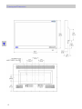
Drawing and Dimensions ------------------------------------------------------------------------- 17
Tab 8
Data Connectors and Pinouts -------------------------------------------------------------------- 18
Cable Bend Radius ---------------------------------------------------------------------------------- 18
Control Connectors and Pinouts ---------------------------------------------------------------- 19
Power Connector and Pinout -------------------------------------------------------------------- 19
Tab 9
Specications ----------------------------------------------------------------------------------------- 20
Video Inputs ---------------------------------------------------------------------------------------- 21
Video Formats ------------------------------------------------------------------------------------- 21
Cleaning and Disinfecting Instructions -------------------------------------------------------- 22
Electromagnetic Compatibility (EMC) Tables ------------------------------------------------ 23
Contact ---------------------------------------------------------------------------------------------- Back

1
ii
Warnings and Cautions
This product is energized from an external electrical power source for class 1 equipment. It is the responsibility of the
installer to test the product’s earth ground to verify that it complies with the hospital, local and national impedance
requirements.
A ground post, located on the back of the product, may be used for the purpose of grounding the unit’s chassis. Any
such ground must be installed in accordance with applicable electrical codes. The ground post is shown on the
Recycling:
Follow local governing ordinances and recycling plans regarding the recycling or disposal of this equipment.
This symbol alerts the user that important information regarding the installation and / or operation of this
equipment follows. Information preceded by this symbol should be read carefully in order to avoid
damaging the equipment.
This symbol warns user that un-insulated voltage within the unit may have sufcient magnitude to cause
electrical shock. Therefore, it is dangerous to make contact with any part inside the unit. To reduce the risk
of electric shock, DO NOT remove cover (or back). There are no user serviceable parts inside.
Refer servicing
to qualied service personnel.
This symbol cautions the user that important information regarding the operation and / or maintenance of
this equipment has been included. Information preceded by this symbol should be read carefully to avoid
damage to the equipment.
This symbol denotes the manufacturer.
This symbol denotes the manufacturer’s European Community representative.
To prevent re or shock hazards, do not expose this unit to rain or moisture. Also, do not use this unit's polarized plug
with an extension cord receptacle or other outlets unless the prongs can be fully inserted. The product is designed to
meet the medical safety requirements for a patient vicinity device.
This product is a Class I medical device. No modications are allowed.
This equipment/system is intended for use by healthcare professionals only.
This monitor complies to the above standards only when used with the supplied medical grade power supply.
Power Cord: Use a hospital grade power cord with the correct plug for your power source.
Disconnect the power cord from the AC mains. The power cord is the only recognized disconnect device.
The MEDICAL EQUIPMENT should be positioned so that its disconnect device is readily accessible.
The product should be powered from a center tapped circuit when used in the US at voltages over 120 volts.
Product is intended for continuous operation.
Model 32" Radiance G2
Power Supply Bridge Power BPM150S24F06
AC Input 100 to 240 Volts at 50 to 60 Hz.
DC Output 24 volts at 6.25 amps
Safety Compliance:
This product is T.U.V. approved with respect to electric shock, re and mechanical hazards only in
accordance with CAN/CSA C22.2 No. 60601-1 and ANSI/AAMI ES60601-1.
Safety Compliance:
This product meets the requirements of EN60601-1 so as to conform to the Medical Device Directive
93/42/EEC and 2007/47/EC (general safety information).
Safety and EMI Compliance: GB9254, GB4943 and GB17625
声明
此为A级 产品。在生活环境中, 该产品可能会造成无线电干扰。在这种情况下, 可能需要用户对其干扰采取切实
可行的措施。

iii
FCC and Council Directives of European Standards:
This device complies with Part 15 of FCC rules and 93/42/EEC and 2007/47/EC of the Council Directives of European Standards. Operation is subject
to the following two conditions: (1) This device may not cause harmful interference, and (2) this device must accept any interference received,
including interference that may cause undesirable results.
1. Use the attached specied cables with the color monitor so as not to interfere with radio and television reception. Use of other cable and
adapters may cause interference with other electronic equipment.
2. This equipment has been tested and found to comply with the limits pursuant to FCC part 15 and CISPR 11. This equipment generates, uses
and can radiate radio frequency energy and, if not installed and used in accordance with the instructions, may cause harmful interference to
radio communications.
IEC:
This equipment has been tested and found to comply with the limits for medical devices to the IEC 60601-1-2. These limits are designed to provide
reasonable protection against harmful interference in a typical medical installation. This equipment generates, uses and can radiate radio
frequency energy and, if not installed and used in accordance with the instructions, may cause harmful interference to other devices in the vicinity.
FCC, Council Directives of European Standards and IEC:
There is no guarantee that interference will not occur in a particular installation. If this equipment does cause harmful interference to radio or
television reception, which can be determined by turning the equipment off and on, the user is encouraged to try to correct the interference by
one or more of the following measures:
• Reorient or relocate the receiving antenna.
• Increase the separation between the equipment and receiver.
• Connect the equipment into an outlet on a circuit different from that to which the receiver is connected.
• Consult your dealer or an experienced radio/TV technician for help.
Declarations of Conformity
Legal Statement
Accessory equipment connected to this product must be certied according to the respective IEC Standards (i.e., IEC 60950-1) for data processing
equipment and IEC 60601-1 for medical equipment. Furthermore, all congurations shall comply with the system standard, IEC 60601-1-1. Anyone
who connects additional equipment to the signal input part or signal output part congures a medical system, and is therefore responsible that
the system complies with the requirements of system standard IEC 60601-1-1. Whoever is responsible for securing the unit to a system needs to
insure that the mounting equipment used with this product complies to IEC standard 60601-1. If in doubt, consult the technical services
department or your local representative.
NDS sells its products through other medical device manufacturers, distributors and resellers and therefore, purchasers of this NDS product should
consult with the entity through which this product was originally purchased regarding the terms of any applicable product warranties provided by
such entity, if any.
NDS neither assumes nor authorizes any person to assume for it any other liabilities in conjunction with and/or related to the sale and/or use of its
products. To ensure proper use, handling and care of NDS products, customers should consult the product specic literature, instruction manual,
and/or labeling included with the product or otherwise available.
Customers are cautioned that system conguration, software, the application, customer data and operator control of the system, among other
factors, affect the product’s performance. While NDS products are considered to be compatible with many systems, specic functional
implementation by customers may vary. Therefore, suitability of a product for a specic purpose or application must be determined by the
consumer and is not warranted by NDS.
NDS SPECIFICALLY DISCLAIMS ALL WARRANTIES OF ANY KIND, WHETHER EXPRESS, IMPLIED AND/OR STATUTORY, INCLUDING, BUT NOT LIMITED
TO WARRANTIES OF MERCHANTABILITY, FITNESS AND/OR OF SUITABILITY FOR A PARTICULAR PURPOSE, AND NON-INFRINGEMENT WITH RESPECT
TO ALL NDS PRODUCTS OR SERVICES. ANY AND ALL OTHER WARRANTIES, REPRESENTATIONS AND/OR GUARANTEES, OF ANY TYPE, NATURE OR
EXTENT, BE IT IMPLIED, EXPRESS AND/OR WHETHER ARISING UNDER OR AS A RESULT OF ANY STATUTE, LAW, COMMERCIAL USAGE, CUSTOM,
TRADE OR OTHERWISE, ARE HEREBY EXPRESSLY EXCLUDED AND DISCLAIMED.
NDS, its suppliers and/or distributors are not liable, directly or by way of indemnity for any special, incidental, consequential, punitive, exemplary or
indirect damages, including but not limited to alleged damages for delayed shipment, non-delivery, product failure, product design or production,
inability to use such products or services, loss of future business (lost prots), or from any other cause, whatsoever, in connection with or arising
from the purchase, sale, lease, rental, installation or use of such NDS products, these terms and conditions, or with respect to any the terms of any
agreement which incorporates these terms and conditions.
SOME JURISDICTIONS DO NOT ALLOW EXCLUSIONS AND DISCLAIMERS OF CERTAIN WARRANTIES OR LIMITATIONS OF LIABILITY, SO THE
LIMITATIONS AND/OR EXCLUSIONS, SET FORTH HEREIN, MAY NOT APPLY. IN THAT EVENT LIABILITY WILL BE LIMITED TO THE GREATEST EXTENT
PERMITTED BY LAW IN THE SUBJECT JURISDICTION.
The information provided in this document, including all designs and related materials, is the valuable property of NDS and / or its licensors and, as
appropriate, they reserve all patent, copyright, and other proprietary rights to this document, including all design, manufacturing reproduction,
use, and sales rights thereto, except to the extent said rights are expressly granted to others.

2
1
Powering On The Unit:
Connect the power supply to the display via the power plug. Plug in the AC adapter. Connect a video
source to the display. Apply power to the peripheral device, then to the display. The NDS logo is displayed,
followed shortly by video.
The electronics, designed by NDS, incorporates proprietary SmartSync™ technology which at initialization,
examines the incoming signal and automatically displays the video image in its proper format. This
eliminates adjustments for most video sources. To ne tune the image, please refer to “Image
Adjustments” on page 5.
First time users and initial test:
Visually, Flat-Panel (LCD) images will look crisper than those of a traditional CRT. For the same reason, live
video may appear a little blocky. Users not familiar with the image differences should familiarize
themselves before utilization in a critical application and determine its usability. It is recommended that
rst time users view the display next to a CRT to familiarize themselves with any subtle differences in
viewing quality.
Quick Startup
Intended Use and Contraindications
Intended Use:
This monitor is intended for use in a medical environment to display high quality video and graphic
images .
Contraindications:
The monitor may not be used in the presence of ammable anesthetics mixture with air, oxygen or nitrous
oxide.
No part of this product may come in contact with a patient. Never touch the product and a patient at the
same time.
This product is capable of displaying Radiology (PACS) images for reference, not diagnostic, purposes only.
For mission critical applications, we strongly recommend that a replacement unit be immediately
available.
Warning: Leaving a xed (constant) image on the monitor for a long period of time can result in
image retention ("burn in"). Avoid leaving a xed image on the monitor’s screen or turn the monitor
off when it is not in use.
Image Retention Notice
About This Manual
This manual is designed to assist the user with proper installation, setup and operation of the display.
Depending on the model and options that were purchased, some of the features and options in this
manual may not apply to the display you are using.
A numbered tab on the side of the page denotes the beginning of a section.

2
3
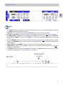
Connector Panels
Notes
1. An S-Video signal may be applied via 2 BNC terminated cables to the Y and C labeled BNC connectors
or a DIN 4 terminated cable, but not both.
2. DVI 1 IN 1920 x 1200 maximum resolution. DVI 2 IN 1920 x 1080 maximum resolution.
3. 3G-SDI 1 and 3G-SDI 2 accept 3G-SDI signals. The provided accessory cable is not 3G-SDI compliant.
4. An RGBS, YPbPr or VGA signal may be applied via the DVI 2 connector or the R / Pr , G / Y / SOG 2, B /
Pb and HS / C-SYNC BNC connectors. The VS BNC is used when the applied signal has both H sync and
V sync.
5. Set the REDRIVE switch to Off when the RGBS and YPbPr signals will not be daisy chained to another
display. The REDRIVE switch is set to On when the RGBS and YPbPr signals will be daisy chained to a
second display.
6. DVI 1, 3G-SDI 1 and S-VIDEO re-drives are always active when the display is powered on.
7. FIBER OPTIC (90R0077 only) and DVI 1 inputs may be connected simultaneously, but may not be
displayed simultaneously.
8. The ND-OS connector is used for installing BIOS upgrades. The ND-OS connector may also be used for
controlling the display. See Communication Port on page 14.

3
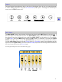
Electrical Symbols
Open (Off) Switch:
This symbol appears on the open, or off, side of the display’s rocker switch.
Closed (On) Switch:
This symbol appears on the closed, or on, side of the display’s rocker switch.
Equipotentiality:
This symbol appears next to the display’s Potential Equalization Conductor. (ground post)

Quick Select
4
4
The QUICK SELECT menu, shown below, is displayed when the keypad’s INPUT button is pressed once. If
the current input is one of the ve shown in the QUICK SELECT menu, it will be illuminated. Select one of
these inputs by pressing the keypad button under the QUICK SELECT key that points to it. For example:
To select DVI-1, press the MENU button under the DVI-1 label. If a selection is not made the QUICK
SELECT menu closes after 10 seconds. The QUICK SELECT menu closes 30 seconds after the last selection
is made. Quick Select changes only the Primary input. If a Secondary input is being displayed and the
input chosen with Quick Select is the same as the Secondary input, then the PIP image will be cleared and
the chosen input will become the Primary input.
Accessing the full input menu is described on page 7.
Control
A 6-button keypad, located bottom right on the front of the display, allows the user to make adjustments
to various display parameters using the On Screen Menu (OSM) system. To display the standard input
menu, press the INPUT button twice.

5
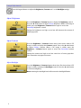
Image Adjustments
Press this keypad button to adjust the Brightness, Contrast and / or the Backlight settings.
Press the Brightness / Contrast button three times, ve times when a PIP
image is visible, to display the Backlight control. Press the ◄ or ► button
to set the backlighting.
Note: Lowering the backlight level will increase the backlight lifetime.
Adjust Backlight
Press the Brightness / Contrast button to display the Brightness control.
Press the ◄ or ► button to adjust Primary brightness. When a PIP image is
visible, press the Brightness / Contrast button again to access the
Secondary brightness control.
Setting the brightness too high or too low will decrease the amount of
visible grayscales.
Adjust Brightness
Press the Brightness / Contrast button twice, three times when a PIP
image is visible, to display the Contrast control. Press the ◄ or ► button
to adjust Primary contrast. When a PIP image is visible, press the
Brightness / Contrast button again to access the Secondary contrast
control.
Setting the contrast too high or too low causes loss of some grayscales.
Color saturation may appear incorrect.
Adjust Contrast

6
5
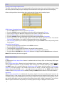
Menu System Overview
Press the MENU button once to open the On Screen Menu System (OSM). The primary and secondary
inputs are shown at the top of the menu.
The Picture menu is displayed when the OSM is opened.
Press the ◄ or ► button to select the menu you want to work with, then press the SCROLL button to
select the parameter. Press the ◄ or ► button to set the parameter to the desired value. Press the MENU
button to save your changes and close the Menu System.
Notes:
1. All parameter names change to the language selected in the Setup menu.
2. Grayed out parameters are not currently accessible.
Languages: English, Deutsch, Français, Italiano, Svenska, Español, Nederlands, Pycckий

7
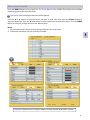
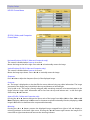
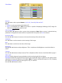
Video Source
Press the INPUT button twice to open the input menu. The Input menu shows a: P for primary input in the
left most column and an: S for secondary input in the column to the right of the cursor. When a secondary
input is selected, its information is shown at the top of the input menu to the right of the primary input
information . Press the SCROLL button to highlight the desired input. Finally, press ◄ button to make it
the primary input or press ► to make it the secondary input. The secondary input may be cleared by
highlighting it using the SCROLL button and pressing the ► button. Selecting a secondary input is
optional. Note: Grayed out inputs are not accessible.
The Input menu will automatically turn off 30 seconds after the most recent button press. It may also be
turned off by pressing the Input button.
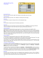
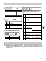
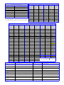
The table below shows which inputs may be secondary when a given input is primary. Inputs marked with
a √ in the secondary column may be designated as the secondary input. Inputs marked with an X in the
secondary column may not be designated as the secondary input. The gray cells denote those inputs that
share a common connector or common electronics and thus may not used simultaneously.
DVI 2, RGBS, YPbPr and SOG 2 share the same input. Thus if one is selected as the primary input, the
others may not be selected as secondary. The same is true for Composite, SOG 1 and VGA.
Input Secondary
DVI 1 DVI Fiber SDI 1 SDI 2 DVI 2 RGBS YPbPr SOG 2 S-Video Composite SOG 1 VGA
DVI 1 √ √ √ √ √ √ √ √ √ √
DVI Fiber √ √ √ √ √ √ √ √ √ √
SDI 1 √ √ √ √ √ √ √ √ √ √ √
P SDI 2 √ √ √ √ √ √ √ √ √ √ √
r DVI 2 √ √ √ √ √ √ √ √
i RGBS √ √ √ √ √ √ √ √
m YPbPr √ √ √ √ √ √ √ √
a S-Video √ √ √ √ √ √ √ √ X √ √
r Composite √ √ √ √ √ √ √ √ X √
y SOG 1 √ √ √ √ √ √ √ √ √ X
SOG 2 √ √ √ √ √ √ √ √
VGA √ √ √ √ √ √ √ √ √ √ X
Inputs Menu

8
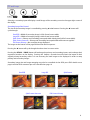
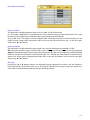
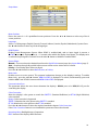
PIP and Swap
Selecting a secondary input will display a small image of the secondary source in the upper right corner of
the display.
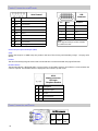
Secondary Image Size Control
The size of the secondary image is controlled by pressing ◄ or ► buttons. Pressing the ► button will
cycle through:
Small PIP = Width of secondary image is 25% of total screen width.
Large PIP = Width of secondary image is 40% of total screen width.
Split-Screen = Primary and Secondary have equal width side by side (half of screen width).
Split-Screen Overscan = Primary and Secondary have equal width with overscan applied
Full Screen Primary = No secondary image displayed.
The images at the bottom of the page illustrate the above sequence.
Pressing the ◄ button will cycle through the above sizes in reverse order.
Pressing the SCROLL / SWAP button will exchange the primary and secondary inputs, and exchange their
respective locations on the display. Pressing the button a second time will restore the inputs to their
original primary/secondary status. It is not necessary for both images to be displayed in order to swap
primary and secondary images.
Secondary image size and image swapping may also be controlled via the GPIO port. GPIO details are on
page 9 and the GPIO connector pin out is described on page 19.
Small PIP Large PIP Split Screen
Full Screen Primary
Split Screen Overscan

9
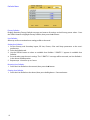
General Purpose Input Output (GPIO):
The GPIO control allows the user to step through the Secondary image sizes as described on page 8, swap
the Primary and Secondary images or display a Record indicator in the upper left corner of the display.
Refer to the Input Menu shown below when setting up the Primary and Secondary inputs.
GPIO
GPIO Primary / Secondary Source Setup:
1. Press the INPUT button twice to open the Input Menu.
2. Press the SCROLL button to highlight the input that will be designated as Primary.
3. Select it by pressing the ◄ button a P appears in the column to the left of the cursor.
4. After the Primary input is chosen you may designate a Secondary input.
5. Press the SCROLL button to highlight the input that will be designated as Secondary.
6. Select it by pressing the ► button an S appears in the column to the right of the cursor. The selected
Secondary input appears as a small PIP in the upper right corner of the display.
7. The Secondary input may be cleared by highlighting it using the SCROLL button and pressing the ►
button again.
Using GPIO Control Fixture:
1. Connect an appropriately wired xture to the GPIO connector.
2. Press the xture’s PIP Size button.
3. The display will cycle through the PIP sizes. See page 8 for the sequence.
4. Press the xture’s Swap button. The Primary and Secondary images swap locations
5. Press the xture’s Record button, the Record indicator is displayed until the Record button is released.
Note: GPIO connector pin out is on page 19.
Setup:
By default the Priority Input Select feature is enabled with the Primary (DVI) and Secondary (SDI) inputs
preselected.
If the Priority Input Select feature has been disabled, then a secondary input (pages 7 and 8) must be
selected before the feature may be re-enabled. After selecting the secondary (PIP) input, press and hold
the INPUT button for 3 seconds. When the Priority Input Select feature becomes active, a “Priority Input
Select On” message appears in the middle of the screen for about 2 seconds, the PIP image is placed
behind the primary, the PIP + and - (◄ and ►) buttons are disabled, and the SWAP button remains
enabled. When Priority Input Select is enabled, holding the INPUT button down for 3 seconds disables it.
Operation:
When Priority Input Select is enabled and the primary signal is lost, the secondary input becomes the
displayed image. If the primary signal is restored, its image becomes the displayed image again, and the
secondary image is placed behind the primary image. If both the primary and secondary signals are lost,
the monitor alternately scans the primary and secondary inputs until a signal is detected on one of them.
When a signal is detected on the primary or secondary input, its image is displayed on the monitor.
Priority Input Select

10
Display Setup
HD SDI Picture Menu
SD SDI, S-Video, and Composite
Picture Menu
Horizontal Position (SD-SDI, S-Video and Composite only):
This control is disabled when Overscan is set to 0.
Moves the image to the left or right. Press ◄ or ► to horizontally center the image.
Vertical Position (SD-SDI, S-Video and Composite only):
This control is disabled when Overscan is set to 0.
Moves the image up or down. Press ◄ or ► to vertically center the image.
Sharpness:
Press ◄ or ► to adjust the sharpness (focus) of the displayed image.
Overscan:
0 = The image is displayed at a size that lls the screen without losing any video information. The image
presented to the display may include black bars top and bottom or left and right.
1, 2, 3, 4, 5 or 6 = The image is linearly enlarged, while remaining centered, in incremental steps. As the
image becomes larger video information will be lost from the top and bottom and / or left and right.
Select using ◄ or ► buttons.
Aspect (SD-SDI, S-Video and Composite only):
Pressing the ◄ or ► button changes the aspect ratio of the image from 4:3 to 16:9 or from 16:9 to 4:3.
Note: Displaying a 4:3 image in 16:9 causes its elements stretched horizontally. Likewise, displaying a 16:9
image in 4:3 causes its elements to be compressed horizontally.
Mirroring:
Pressing the ◄ or ► button presents the displayed image swapped from right to left and displays a
mirroring indicator in the lower right corner. Pressing the ◄ or ► button again returns the image to its
normal left to right orientation and removes the mirroring indicator

11
VGA,SOG, RGBS and YPbPr
Picture Menu
Horizontal Position:
Moves the image to the left or right. Press ◄ or ► to horizontally center the image.
Vertical Position:
Moves the image up or down. Press ◄ or ► to vertically center the image.
Sharpness:
Press ◄ or ► to adjust the sharpness (focus) of the displayed image.
Phase:
Press ◄ or ► to adjust the phase of the display’s pixel clock.
Frequency:
Adjusts the frequency of the display’s pixel clock. With Scaling set to Fill adjust until image just lls the
screen horizontally. Press ◄ or ► to adjust the frequency of the display’s pixel clock.
Scaling (Graphics):
This parameter is enabled when the input signal is not 16:9, not interlaced and not 480P or 576P.
Fill = Expands the video image to ll the entire screen. The aspect ratio may not be accurately displayed.
Aspect = Expands the video image until its largest dimension lls the screen. Image may be displayed with
black bars on the top and bottom or the left and right. 1:1 = Displays the video data in its native size and
aspect ratio. Image may be displayed with black bars on the top and bottom and on the left and right.
Select using ◄ or ► buttons.
Overscan (Video):
This parameter is enabled when the input is 16:9 or 480P or 576P or interlaced.
0 = The image is displayed at a size that lls the screen without losing any video information. The image
presented to the display may include black bars top and bottom or left and right.
1, 2, 3, 4, 5 or 6 = The image is linearly enlarged, while remaining centered, in incremental steps. As the
image becomes larger video information will be lost from the top and bottom and / or left and right.
Select using ◄ or ► buttons.
SmartSync™ / Alternative Modes
On initialization NDS’ proprietary SmartSync technology examines the incoming signal and automatically
displays the video image in its proper format. To run SmartSync highlight the SmartSync / Alternative
Modes parameter and press the ◄ button.
To select an alternate mode (format) highlight the SmartSync / Alternative Modes parameter and press
the ► button. The mode increments each time the ► button is pressed until the selected mode equals
the maximum available, the next time ► pressed the rst mode is restored. Alternative Modes are used
to manually distinguish between modes (resolutions) whose timing characteristics are very close.
Mirroring:
Pressing the ◄ or ► button presents the displayed image swapped from right to left and displays a
mirroring indicator in the lower right corner. Pressing the ◄ or ► button again returns the image to its
normal left to right orientation and removes the mirroring indicator

12
DVI Digital Picture Menu
Overscan (Video)
This parameter is enabled when the input is 16:9 or 480P or 576P or interlaced.
0 = The image is displayed at a size that lls the screen without losing any video information. The image
presented to the display may include black bars top and bottom or left and right.
1, 2, 3, 4, 5 or 6 = The image is linearly enlarged, while remaining centered, in incremental steps. As the
image becomes larger video information will be lost from the top and bottom and / or left and right.
Select using ◄ or ► buttons.
Scaling (Graphics)
This parameter is enabled when the input signal is not 16:9, not interlaced and not 480P or 576P.
Fill = Expands the video image to ll the entire screen. The aspect ratio may not be accurately displayed.
Aspect = Expands the video image until its largest dimension lls the screen. Image may be displayed with
black bars on the top and bottom or the left and right. 1:1 = Displays the video data in its native size and
aspect ratio. Image may be displayed with black bars on the top and bottom and on the left and right.
Select using ◄ or ► buttons.
Mirroring:
Pressing the ◄ or ► button presents the displayed image swapped from right to left and displays a
mirroring indicator in the lower right corner. Pressing the ◄ or ► button again returns the image to its
normal left to right orientation and removes the mirroring indicator

13
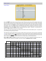
Color Menu
Gamma:
Press ◄ or ► to select a preset Gamma (1.8, 2.0, 2.2, 2.4 or 2.6), Video or PACS
Notes:
1. Video is a color corrected Look Up Table (LUT).
2. PACS is a DICOM-like LUT. Note: This product is capable of displaying Radiology (PACS) images for
reference, not diagnostic, purposes only.
Color Temperature:
Press the ◄ or ► button to select a preset color temperature. Note: When a preset is selected and any
parameter is changed, the current values are copied to the User presets and User is selected.
Red, Green, Blue:
Press the ◄ or ► button to increase or decrease the intensity of the selected color.
Saturation:
Press ◄ or ► to set the saturation (color intensity) of the image.
Hue:
Press ◄ or ► to set the hue (color tint) of the image.
Brightness:
Press the ◄ or ► button to adjust brightness. This is a duplicate of the Brightness control described on
page 5.
Contrast:
Press the ◄ or ► button to adjust contrast. This is a duplicate of the Contrast control described on page 5.
Video Level:
Normal: Provides a dynamic range equivalent to the incoming signal with no change.
Expanded: Expands the signal level such that an input signal with range 16 (black) to 235 (white) will be
expanded to a range of 0 (black) to 255 (white). Note: If a signal is already full range (0 to 255), changing
the setting to Expanded will cause the signal to “clip” or “saturate”.
Press the ◄ or ► button to select.
Page is loading ...
Page is loading ...
Page is loading ...
Page is loading ...
Page is loading ...
Page is loading ...
Page is loading ...
Page is loading ...
Page is loading ...
Page is loading ...
Page is loading ...
Page is loading ...
Page is loading ...
Page is loading ...
Page is loading ...
Page is loading ...
-
 1
1
-
 2
2
-
 3
3
-
 4
4
-
 5
5
-
 6
6
-
 7
7
-
 8
8
-
 9
9
-
 10
10
-
 11
11
-
 12
12
-
 13
13
-
 14
14
-
 15
15
-
 16
16
-
 17
17
-
 18
18
-
 19
19
-
 20
20
-
 21
21
-
 22
22
-
 23
23
-
 24
24
-
 25
25
-
 26
26
-
 27
27
-
 28
28
-
 29
29
-
 30
30
-
 31
31
-
 32
32
-
 33
33
-
 34
34
-
 35
35
-
 36
36


NDS Radiance G2 32" Owner's manual
- Category
- TVs & monitors
- Type
- Owner's manual
Ask a question and I''ll find the answer in the document
Finding information in a document is now easier with AI
Related papers
-
NDS Radiance G2 24” Owner's manual
-
-
-
-
-
-
-
-
-
Other documents
-
Philips C271P4QPJEW/69 User manual
-
Barco E192HSA User manual
-
 Steris MON-STE55HD-MD Operating instructions
-
Barco MDSC-2232 User guide
-
Barco MDSC-2324 User guide
-
-
Barco MDSC-2224 User guide
-
-
-
Barco MDSC-2326 High Bright User guide
