Page is loading ...

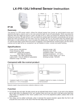
Summary
Specifications
Product size
Name of each part
Microwave Sensor Light
assume the follow-up power supply and provide 5W
power to the induction lamp system. The power supply
of the standby battery can last for more than 1 hour and
can also be adjusted according to the customer's
demand. However, the duration of the standby battery
storage is inversely proportional to the brightness. This
product can be widely used in corridors, toilets,
elevator entrances and other energy-saving
application Spaces.
The product comes in two configurations: an induction
lamp with dual AC/DC systems for emergency
management; One is a smart sensor lamp without
emergency functions. Customers can choose the
configuration according to their needs. It is necessary
to choose emergency lights under most
circumstances. Occasional power outages without
lighting can cause a lot of trouble and even danger, so
this product with emergency lights is a wise choice.
The shell of the product adopts aluminum alloy body,
frosted baking process, and other parts adopt PC
anti-ultraviolet engineering plastics, which greatly
enhances the service life of the product.
This is a new concept design of intelligent wall
installation series LED microwave induction lamp,
additional power failure standby battery power supply
lighting function. The lighting part is automatically
managed by a dual system of municipal power supply
and standby battery power supply. When the power
supply of the power network is interrupted, the
self-provided battery of the system will automatically
Induction information
Parameter setup Method: potentiometer
The following settings may require multiple adjustments
to meet your requirements.
LED quantity: 72PCS(2835)
Working temperature: -20~+55
Operating Temperature: -10 - +40°C
Probe movement speed: 0.6-1.5m/s
relative Humidity: <93%RH
Static power consumption: 0.5W
LX-MV-131LED-D
250mm
135mm
103mm
Power source: 220-240VAC, 50/60Hz
Rated LED: 8W/16W Max.(AC) 5W Max.(DC)
Charging power: 5W Max.
HF system: 5.8GHz
Battery: 3.7V / 1800mAH lithium battery(18650)
Continuous illumination time: ≥60min
Transmission power: <0.2mW
Detection angle: 180°
Time setting: 10sec to 12min (adjustable)
Detection range(22 ): 1-5m (radii.) (adjustable)
Light-control: <10-2000LUX(adjustable)
Installation height: 1.5-3m
Use high quality PC lampshade.Strengthen the flexible
refraction of light.And its function of anti-ultraviolet makes
the shade not easy to turn yellow and be broken.
LED lamp consumes power 80% less than incandescent
lamp and 50% less than fluorescent lamp.
Upper part of the light
Battery capacity high,
medium and low indicator
1. Sensitivity setting
2. Delay setting
3. Light control settings
4. Low brightness exit
time setting
5. 8W/16W machine
power switch button
Aluminium Alloy
The lower part of the light
1 2 3 4 5
Height of installation1.5~3m Detection range22
5m
Detection angle
180°

Battery voltage indicator
battery voltage drops, the indicator lights go out one by
one; When the 25% voltage indicator starts flashing, it
indicates that the battery is about to run out.
When the indicator light of this product is fully on, it does
not need to be charged, only when % brightness and
completely off, it needs to be charged.
It is divided into 4 levels:
25%, 50%, 75% and 100%.
During the charging process,
the indicator is flashing.
When it is full, the indicator is
all on.
When discharging, as the
Connection
Note: after the light goes out, it needs to wait for nearly 2 seconds
before it can be sensed again. The lights will only turn on when a
signal is detected at the end of this time.
Proper use of delay adjustment: it is used to adjust the delay time
from the light on to the automatic light off after the sensor
detects human movement. Users can adjust according to actual
demand. Because of the continuous induction function of
microwave induction products, in short, the system will restart
the timing of any sensor before the end of the delay time, and the
lights will not go out as long as people move within the detection
range. Therefore, users are advised to reduce the delay time to
achieve energy saving.
illumination value is about the day when the clockwise
spin is in the end.
unobstructed 360° rotation. Its adjustment limit is 230 °, please
pay attention.
It can be set in the range of 10 seconds
(anticlockwise to the bottom) to 12
minutes (clockwise to the bottom), and
the timing will be restarted when the
moving signal is detected before the end
(3)Delay setting
Note: this detection range value is measured by the body of a
person 1.6~1.7 meters tall, of medium build, and with a walking
speed of 1.0~1.5 meters/second. If the height, shape and walking
speed of the human body change, the sensing distance will also
change.
Notice: when using the product, please adjust the product
sensitivity to the appropriate position, do not adjust the product
sensitivity to the maximum, to avoid improper operation caused
by wind starting curtains, leaves, small animals, power grid and
electrical equipment, which may cause the product not to work
properly. When it is found that the product does not work
properly, the user can try to lower the sensitivity appropriately
before carrying out the test. Before or during the installation of
the product, if the functional test is carried out, the personnel
must leave the product sensor area and do not walk around to
prevent continuous work of the sensor due to human movement.
Friendly reminder: the installation distance of two or more
products must be more than 4 meters, otherwise it will cause
mutual interference and lead to misoperation.
Detection range is the term used to
describe the radii of the more or less
circular detection zone produced on the
ground after mounting the sensor light at
a height of 3m, turn the reach control
fully anticlockwise to select minimum
(3)Detection distance setting (sensitivity)
reach (approx.1m radii), and fully clockwise to select
maximum reach (approx. 5m radii).
The work illumination value can be
adjusted <10-2000LUX range.
The working illumination value is about
10LUX when rotating anticlockwise to
the bottom, and about 2000LUX when
rotating clockwise to the bottom. When
(3)Light-control setting
walking during the day to test or adjust the detection
area, this knob must be rotated clockwise to the bottom.
% brightness exit time: When it is
adjusted to 0, there is no
semi-brightness, and the induction
lamp is completely off; On the contrary,
the induction delay is maintained at %
brightness, and the delay is
determined by the actual potentiometer
(4) Low brightness time exit setting
position.
Note: % brightness exit is divided into: time exit and light
control exit. When the light control is >100Lux,the
semi-bright will automatically exit the energy saving.
Note: When adjusting the five function knobs, do not use too
much force because the five knobs are mounted directly on the
component. When adjusting the starting point to the end point,
there is a small limit device inside. When you use too much force
during operation, the limit device will be damaged, resulting in an
The single section can replace
the 18650 lithium battery.
NOTE: Make sure the positive and
negative electrodes are consistent
with the label when installing the
battery.
8W/16W machine power
switch button.
N
L
N L - Power
- Ground
Installation is based
on the wiring
diagram provided.

Installation Attention
This manual for the content of this product programming
at time, We will not notice if there are any updates.
The contents of the instruction manual are strictly
prohibited for any reproduction by other purposes
without the permission of the company.
Installation
(1) turn off the power.
(2) open the upper
cover and remove the
base before installation.
(3) connect the power
cord to the terminal
according to the wiring
mark .
(4) install the bottom
1.The LEDS in serial can function when all the seals
installed in place.
2.Please don’t remove or connect with other lamp when
powered on.
3.When the LEDS in serial are damaged ,you need
experienced technician to repair using the same rating
LEDS.
● Please confirm with prefessional installation.
● For safety purposes, please cut off power before
installation and removal operations.
● Any losses caused by improper operation,the
manufacturer does not undertake any
responsibility.
cover in the selected position according to figure 1.
(5) fix the lamp body on the base and install the upper
cover.
figure 1
figure 2
103mm
6.4mm
40.3mm
31.8mm
6.4mm
6.4mm
Warning!
1. Please keep it away from the children.
2. Please avoid fire/high temperature/damp places for
installation.
3. Please confirm when shut off the power cord access.
Bottom
Cover
Metal lamp body
/