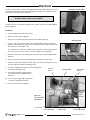
Town & Country Fireplaces WS38 Installation guide
- Category
- Fireplaces
- Type
- Installation guide

MODEL: TCWS38
SERIES D2
DIRECT VENTED
DECORATIVE
GAS APPLIANCE
TCWS38D2
INSTALLATION
MANUAL
301123-48 TCWS38D2 100001138-50
Visit www.townandcountryfireplaces.com for the most recent version of this manual
WARNING: If the information in these
instructions is not followed exactly, a re or
explosion may result causing property damage,
personal injury or death.
FOR YOUR SAFETY
Installation and service must be performed
by a qualied installer, service agency or the
gas supplier.
WHAT TO DO IF YOU SMELL GAS
• Do not try to light any appliance.
• Do not touch any electrical switch.
• Do not use any phone in your building.
• Immediately call your gas supplier from
a neighbour’s phone. Follow the gas
supplier’s instructions.
• If you cannot reach your gas supplier call
the re department.
Do not store or use gasoline or other ammable
vapors and liquids in the vicinity of this or any
other appliance.
This appliance may be installed in an after market
permanently located, manufactured home (USA only)
or mobile home, where not prohibited by local codes.
This appliance is only for use with the type of gas
indicated on the rating plate. This appliance is
not convertible for use with other gases, unless a
certied kit is used.
This appliance is suitable for installation in a
bedroom or bed sitting room.
INSTALLER: Leave this manual with the appliance.
CONSUMER: Retain this manual for future reference.
INSTALLATION MANUAL
This is a decorative product and
is not intended to be used as a
heating appliance.

Table of Contents
HOT GLASS WILL CAUSE
BURNS.
DO NOT TOUCH GLASS UNTIL
COOLED.
NEVER ALLOW CHILDREN TO
TOUCH GLASS.
!
DANGER
A barrier designed to reduce the risk of burns from the
hot viewing glass is provided with the appliance and
shall be installed for the protection of children and
other at-risk individuals.
Attention!
• Turn off the main gas supply for
the appliance during installation
or maintenance of the receiver/
module device.
• Turn off main gas supply for the
appliance prior to removing or
reinserting the batteries.
• In case of remote control mal-
function, turn off the replace
using the “on/off” main switch
located on the wall.
• For installation/maintenance,
turn off the replace at the on/off
switch located on the wall and at
the replace power supply circuit
breaker.
Caution ...................................................................................... 3
Safety ........................................................................................ 3
Important Note for the Commonwealth of Massachusetts ....... 4
Fireplace Dimensions ................................................................ 5
Minimum Clearances to Combustible Material ......................... 5
Installation Requirements .......................................................... 6
Manufactured (Mobile) Home .................................................... 6
Door Frame Removal ................................................................ 6
Standoffs ....................................................................................7
Locating The Fireplace ...............................................................7
Framing and Finishing ............................................................... 8
Non - combustible board area ........................................... 9
Steel Stud Framing Kit ............................................................ 10
Frame assembly instructions. .......................................... 12
Fixed Lintel .............................................................................. 13
Framing Kit Adjustment ................................................... 13
Fireplace Facing Allowance ........................................... 14
Hearth Extension ..................................................................... 15
Electrical .................................................................................. 16
Wall Switch and Remote Control .............................................17
Selecting Natural Vent and Power Vent Modes ........................17
Home Automation ................................................................... 18
Gas Supply / Connections ...................................................... 19
Gas Pressure Check ................................................................ 19
Venting ..................................................................................... 20
Wall Termination Venting ......................................................... 20
Exterior wall opening:....................................................... 20
Wall thimble: ...................................................................... 21
Vent pipe: ......................................................................... 22
Wall vent terminal: ............................................................ 22
Wall Termination Venting Chart ............................................... 23
Roof Termination Venting Chart ............................................... 24
Roof Termination Venting ........................................................ 25
Ceiling Opening: ............................................................... 25
Ceiling Firestop: ............................................................... 25
Vent Pipe: ......................................................................... 25
Roof Support Bracket: ..................................................... 25
Roof Vent Terminal: .......................................................... 26
Vent Terminal Minimum Clearances .........................................27
Vent Terminal Clearance .......................................................... 28
Vent Pipe Sealant .................................................................... 28
Vent Restrictor Adjustment ..................................................... 29
Wall Shield/ .............................................................................. 30
Ceiling Firestop Thimble ........................................................... 30
Roof Termination Kit ................................................................ 30
Wall Termination Kit ................................................................. 30
Vent Pipe Dimensions ..............................................................31
Vent Offset Chart ..................................................................... 32
Firebox Panels Installation ...................................................... 33
Panels Removal for Valve Service ........................................... 35
Finishing Touch Trim Kit Installation ........................................ 36
Linking Remote Handset to the Fireplace ............................... 38
Step 1: Procedure for linking / pairing wall
switch to replace ............................................... 38
Step 2: Procedure for linking / pairing wall
switch to remote handset ................................... 39
Maintenance ............................................................................ 40
Glass Panel: ..................................................................... 40
Annual Inspection: ............................................................ 40
Periodically: ...................................................................... 40
Wiring Diagram .........................................................................41
Rating Label ............................................................................ 42
100001138-50 2TCWS38D2_301123-48

Caution
FOR YOUR SAFETY - Do not install or operate your Town & Country replace without rst reading and understanding
this manual. Any installation or operational deviation from the following instructions voids the Town & Country Fireplaces
Warranty and may prove hazardous.
This appliance and its individual shut off valve must be disconnected from gas supply piping system during any pressure
testing of that system at test pressures in excess of 1/2 psig (3.5 kPa).
This appliance must be isolated from the gas supply piping system by closing its individual manual shut off valve during
any pressure testing of the gas supply piping system at test pressures equal to or less than 1/2 psig (3.5 kPa).
Note: When lit for the rst time, the appliance will emit a slight odour for a couple of hours. This is due to the curing
of paints, sealants and lubricants used in the manufacturing process. This condition is temporary. Open doors and
windows to ventilate area. Smoke and fumes caused by the curing process may cause discomfort to some individuals.
Do not use the replace if any part has been under water. Immediately call a qualied service technician to inspect the
replace and to replace any part of the control system and any gas control which has been under water.
Due to high temperatures, this gas appliance should be located out of trafc and away from furniture and draperies.
Children and adults should be alerted to the hazards of high surface temperatures and should stay away to avoid burns
or clothing ignition.
Young children should be carefully supervised when they are in the same room as the appliance. Toddlers, young
children and others may be susceptible to accidental contact burns. A physical barrier is recommended if there are at
risk individuals in the house. To restrict access to the replace or stove, install an adjustable safety gate to keep toddlers,
young children and other at risk individuals out of the room and away from hot surfaces.
Clothing or other ammable material should not be placed on or near the appliance.
Any grill, panel or door removed for servicing the unit must be replaced prior to operating. Failure to do so may create a
hazardous condition.
Installation and repair should be done by a qualied service person. The appliance should be inspected before use and
at least annually by a professional service person. More frequent cleaning may be required due to excessive lint from
carpeting, bedding material, etc. It is imperative that control compartments, burners and circulating air passageways of
the appliance be kept clean.
It is our policy that no responsibility is assumed by the Company or by any of its employees or representatives for any
damages caused by an inoperable, inadequate, or unsafe condition which is the result, either directly or indirectly, of any
improper operation or installation procedures.
This appliance must not be connected to a chimney ue serving a separate solid fuel burning appliance.
We recommend that our gas hearth
products be installed and serviced
by professionals who are certied
in the United States by the National
Fireplace Institute® (NFI) as NFI
Gas Specialists
Safety
WARNING: This product
can expose you to chemicals
including ceramic bers,
which are known to the State
of California to cause cancer, and carbon
monoxide, which is known to the State of
California to cause birth defects or other
reproductive harm.
For more information go to
www.P65Warnings.ca.gov.
This warning is applicable to all
Pacific Energy Fireplace Products
100001138-50
3
TCWS38D2_301123-48

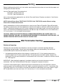
Important Note for the Commonwealth of Massachusetts
From Massachusetts Rules and Regulations 248 CMR 5.08:
(a) For all side wall horizontally vented gas fuelled equipment installed in every dwelling, building or structure used in whole or in part for residential
purposes, including those owned or operated by the Commonwealth and where the side wall exhaust vent termination is less than seven (7) feet
above nished grade in the area of the venting, including but not limited to decks and porches, the following requirements shall be satised.
1. INSTALLATION OF CARBON MONOXIDE DETECTORS. At the time of installation of the side wall horizontal vented gas fuelled equipment, the
installing plumber or gas tter shall observe that a hard wired carbon monoxide detector with an alarm and battery back-up is installed on the oor
level where the gas equipment is to be installed, in addition, the installing plumber or gas tter shall observe that a battery operated or hard-wired
carbon monoxide detector with an alarm is installed on each additional level of the dwelling, building or structure served by the side wall horizontal
vented gas fueled equipment. It shall be the responsibility of the property owner to secure the services of qualied licensed professionals for the
installation of hard-wired carbon monoxide detectors.
a. In the event that the side wall horizontally vented gas fueled equipment is installed in a crawl space or an attic, the hard-wired carbon monoxide
detector with alarm and battery back-up may be installed on the next adjacent oor level.
b. In the event that the requirements of this subdivision cannot be met at the time of completion of installation, the owner shall have a period of thirty
(30) days to comply with the above requirements; provided, however, that during said thirty (30) day period, a battery operated carbon monoxide
detector with an alarm shall be installed.
2. APPROVED CARBON MONOXIDE DETECTORS. Each carbon monoxide detector as required in accordance with the above provisions shall
comply with NFPA 720 and be ANSI/UL 2034 listed as IAS certied.
3. SIGNAGE. A metal or plastic identication plate shall be permanently mounted to the exterior of the building at a minimum height of eight (8) feet
above grade directly in line with the exhaust vent terminal for the horizontally vented gas fueled heating appliance or equipment. The sign shall
read, in print size no less than one-half (1/2) inch in size, “GAS VENT DIRECTLY BELOW. KEEP CLEAR OF ALL OBSTRUCTIONS”.
4. INSPECTION. The state or local gas inspector of the side wall horizontally vented gas fueled equipment shall not approve the installation unless,
upon inspection, the inspector observes carbon monoxide detectors and signage installed in accordance with the provisions of 248 CMR 5.089(2)
(a) 1 through 4.
(b) EXEMPTIONS. The following equipment is exempt from 248 CMR 5.089(2)(a) 1 through 4.
1. The equipment listed in Chapter 10 entitled “Equipment Not Required To Be Vented” in the most current edition of NFPA 54 as adopted by the
Board; and
2. Product Approved side wall horizontal vented gas fueled equipment installed in a room or structure separate from the dwelling, building or structure
used in whole or in part for residential purposes.
(c) MANUFACTURER REQUIREMENTS – GAS EQUIPMENT VENTING SYSTEM PROVIDED. When the manufacturer of Product Approved side wall
horizontally vented gas equipment provides a venting system design or venting system components with the equipment, the instructions provided
by the manufacturer for installation of the equipment and the venting system shall include:
1. Detailed instructions for the installation of the venting system design or the venting system components; and
2. A complete parts list for the venting system design or venting system.
(d) MANUFACTURER REQUIREMENTS – GAS EQUIPMENT VENTING SYSTEM NOT PROVIDED. When the manufacturer of a Product Approved
side wall horizontally vented gas fueled equipment does not provide the parts for venting the fuel gases, but identies “special venting systems”, the
following requirements shall be satised by the manufacturer.
1. The referenced “special venting system” instructions shall be included with the appliance or equipment installation instructions; and
2. The “special venting systems” shall be Product Approved by the Board, and the instructions for that system shall include a parts list and detailed
installation instructions.
(e) A copy of all installation instructions for all Product Approved side wall horizontally vented gas fueled equipment, all venting instructions, all parts
lists for venting instructions, and/or all venting design instructions shall remain with the appliance or equipment at the completion of the installation.
100001138-50 4TCWS38D2_301123-48

UNIT MAY BE RECESSED UP TO 4 1/2” WITH
NONCOMBUSTIBLE MASONRY TYPE MATERIAL
Minimum Clearances:
Side standoffs .................................. 0 in. (0 mm)
Back standoffs ................................. 0 in. (0 mm)
Top standoffs .................................... 0 in. (0 mm)
Bottom of appliance ......................... 0 in. (0 mm)
Adjacent side wall ............................ 4 in. (102 mm)
Ceiling to appliance ........................ 24 in. (610 mm)
*Mantel to appliance See Figure #2
**Maximum Mantel extension See Figure #2
Mantel support ................................. 4 in. (102 mm)
Vent pipe including Elbows ...... 1 3/4" in. (45 mm)
* MANTEL CLEARANCE
A 9”
B 6”
C 3”
** MANTEL DEPTH
D 12”
E 6 3/4”
F 1 1/2”
MANTEL CLEARANCE
CHART
Fireplace Dimensions
Minimum Clearances to Combustible Material
22 1/8"
7 5/8"
45 1/16"
23 3/8"
57 15/16"
48 7/16"
40 7/16"
5 15/16"
24 7/8"
29 3/4"
22 1/8"
Figure 1: TC38WS Dimensions.
A
B
C
D
E
F
Steel Frame
Non-combustible board
Combustible board
Stand off
= Non-combustible zone. Do not install
any combustible material, electrical wiring
or gas plumbing in this area.
Top of lintel bar
Figure 2: TCWS38 Mantel clearances.
21 5/8"
24"
4“
CEILING
ADJACENT WALL
OR MANTEL SUPPORT
6”
COMBUSTIBLE FLOOR
*
**
Figure 3: TCWS38 Mantel clearances.
100001138-50
5
TCWS38D2_301123-48

Figure 6: Handle.Figure 4: Safety barrier screen.
The Town & Country Fireplace installation and venting must conform to the current CAN/CGA-B149 installation code (in
Canada) or the current National Fuel Gas Code, ANSI Z223.1 (in the USA), and approved per local codes. Only qualified
(licensed or trained) personnel should install this product.
In the state of Massachusetts, only a licensed Plumber and Gas Fitter may install this product.
In some jurisdictions, the Town & Country Fireplace may be installed in Manufactured Homes after the "rst sale". Consult local codes
for approval. The replace must be fastened in place.
Install in accordance with the current standard Mobile Homes, CAN/CSA Z240 MH (in CANADA), and the Manufacturer's Home
Construction and Safety Standard, Title 24 CFR, Part 3280 or the current Standard for Fire Safety Criteria for Manufactured Home
Installations, Sites and Communities ANSI/NFPA 501A (in the USA).
Warning: Turn off the fireplace, and allow ample time for the unit to cool before proceeding.
Caution: The ceramic glass is very fragile, and should be handled with care.
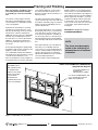
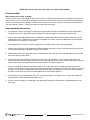
The door frame is held in place by two spring-loaded latches that are operated by a one-piece latch handle.
Remove safety barrier screen (Figure 4) by prying the top portion of the screen toward you, then lift the screen from its tabs (inset)
located at the base of the door frame.
1. Remove the TC Finishing Touch Trim Kit from the door frame. (If installed)
2. Using a screwdriver (Figure 5) or other similar object, push against the notch in the top of the latch and grab the bottom of the
latch handle as it protrudes (Figure 6). Lift handle until latch hook disengages. Repeat for other side while holding glass so it does
not tip out.
3. Tilt the top of the door frame out to clear the top edge of the unit. Grasp the sides of the frame and lift up and out to disengage
from its bottom track.
4. Place the door frame in a safe place to avoid damage.
5. Re-assemble in reverse order. Latch handle should snap into place and be ush with door frame when engaged correctly.
6. Reinstall Trim Kit if required.
7. Reinstall safety barrier screen.
TIP:
To ensure glass is properly latched, grasp the top left and right sides of the
glass frame, under moderate pressure it should pull forward and return to
original position evenly on both sides.
Door Frame Removal
HANDLE
SAFETY BARRIER
SCREEN
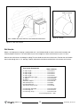
Installation Requirements
Manufactured (Mobile) Home
Figure 5: Accessing handle.
100001138-50 6TCWS38D2_301123-48

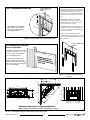
The standoffs are shipped loose inside the replace and must be installed on the top and the side of the replace as shown in
Figure 7. Do this once the replace is on site and in position.
In planning the installation for the replace, it is necessary to determine where the unit is to be installed, location of vent system and
where gas supply piping may be plumbed. Various installations are possible, such as, into an existing wall, a corner, a built-in wall or a
wall projection (Figure 8). Due to high temperatures, do not locate this replace in areas of high trafc or near furniture or draperies.
The minimum clearances from the fireplace to combustible surfaces must be adhered to and are shown in Figure 2 and Figure 3.
EXAMPLES OF COMMON LOCATIONS. SEE
FIGURE 9 FOR FRAMING DIMENSIONS
HANDLE
CONTROL
BOX
TOP STANDOFFS
Locating The Fireplace
Standoffs
Figure 7: TCWS38D Stand offs
Figure 8: TCWS38D Possible locations.
100001138-50
7
TCWS38D2_301123-48

Note: The fireplace should be in place
and venting installed before framing
in or building an enclosure around the
unit.
The Town & Country replace must be
framed in as described below or totally
enclosed with non-combustible material,
such as facing brick.
Determine the total thickness of facing
material to be used. A thickness of 3/4”
will allow the nishing surface to be ush
with the front of the unit. If preferred,
additional masonry type non-combustible
material can be installed above and to
the sides up to 4 1/2 inches proud of the
appliance. The nishing material must
not interfere with glass frame access or
movement.
A Steel Stud Framing Kit is supplied with
the replace and must be used unless the
replace is totally enclosed with
non-combustible material. Assemble the
framing kit as per the instructions on page
12 of this manual. Attach the steel
frame to the replace once the replace is
in its nal position. Secure the steel frame
to the framing brackets on each side of
the unit. Ensure that the studs are set
back far enough to allow for thickness of
nishing surface.
The sides, back and top of the replace
can be framed in up to the steel studs and
the replace standoffs using conventional
lumber. Consult local building codes for
specic requirements.
Due to high temperatures, non-combusti-
ble backer board, such as cement board
or its equivalent, must be used to sheet
in the front of the replace, extending 11
7/8” above and 10 1/8” to the side of the
framing edge bars (Figure 10). Standard
sheet rock (dry wall) may be used beyond
this.
If the backer board is not to be nished
with other non-combustible material
such as tiles, it is recommended that top
sections of the board be a single sheet of
calcium silicate board or its equivalent.
Taped and mudded joints may crack due
to the elevated temperatures.
Chase Insulation: When installing this
replace against a non-insulated exterior
wall or chase, it is recommended that the
outer walls be insulated to same degree as
other exterior walls. Do not place replace
directly against the insulation. Cover the
insulation and plastic vapour barrier with
a solid surface, such as dry wall (sheet
rock). Consult local codes. Do not insulate
or use plastic vapour barrier within the
framing kit.
CAUTION: See “Figure 12” on page
9 BEFORE PROCEEDING.
NOTE:
The chase must be properly
sealed at the ceiling level or
between floors in a multilevel
installation.
Framing and Finishing
IT IS HIGHLY RECOMMENDED THAT
A FULL HEADER BE INSTALLED
ABOVE THE FRAMING KIT
61 5/8”
45 1/8”
ALL OTHER FRAMING CAN
BE DONE WITH
CONVENTIONAL LUMBER
NON-COMBUSTIBLE
ZONE. DO NOT INSTALL
ANY COMBUSTIBLE
MATERIAL, ELECTRICAL
WIRING, INSULATION,
PLASTIC VAPOR
BARRIER OR GAS
PLUMBING WITHIN THE
STEEL STUD FRAMING
STEEL STUD FRAMING KIT DIMENSIONS
(Supplied with fireplace)
Figure 9: TCWS38D with steel frame
100001138-50 8TCWS38D2_301123-48

NON-COMBUSTIBLE
BOARD
If nishing the wall above the unit with paint,
the framing kit shipped with the unit should
be discarded. Use full sheets of calcium
silicate board or equivalent and full length
metal studs to nish and frame around the
unit.
Calcium silicate board is a high grade
material with cement, quartz and natural
minerals as the main raw materials. (Note:
Calcium Silicate is 1/2” thick)
CAUTION: Calcium Silicate board can be
damaged if dropped or struck. Handle with
care. Inspect board prior to installation and
do not use if cracked.
NOTE: It is recommended to pre-drill
mounting holes in the board prior to securing
to the framing. This will prevent the board
from cracking.
MINIMUM COMBUSTIBLE FRAMING DIMENSIONS
NOTE: Fireplace should be in its final location before framing.
NON-COMBUSTIBLE RECESSED
INSTALLATION DETAIL
This replace may be recessed up
to a maximum depth of 4 1/2”. This
recess must be constructed from
non- combustible material.
It is important to note that any
nishing material used must not
interfere with the glass door being
able to open in the event of ignition
of excess gas buildup.
Calcium silicate board
Non - combustible board area
NON-COMBUSTIBLE MATERIAL
MUST EXTEND 11 7/8" ABOVE
AND 10 1/8" TO THE SIDES OF
THE FRAMING EDGES.
NON-COMBUSTIBLE
BOARD IN THESE
AREAS
11 7/8”
10 1/8”
Figure 10: Non-combustible board within frame.
Figure 11: TCWS38D Recessed installation details. Figure 12: Non-combustible board
location.
61 7/8"
26 11/16"
72"
37 3/4"
75 1/2"
1/2"
61 7/8"
101 13/16"
45 3/8"
61 7/8"
RANGE
22 1/2"
to
24 3/8"
24 7/8”
RANGE
1/2" - 2 1/2"
11 3/4"
FRAMING
LINTEL
Figure 13: TCWS38D Minimum combustible framing dimensions.
100001138-50
9
TCWS38D2_301123-48

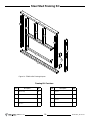
Item Description Qty.
1 SCREW, WAFER #8 x 1/2
(Not shown)
Pkg
40
2 STUD, SIDES 45” L 2
3 STUD, OUTER SIDES 45” L 2
4 STUD, UPPER/LOWER
61 1/2” L
2
Item Description Qty.
5 INNER CROSS BRACE
39 3/4” L
1
6 STUD, CENTER 23 1/4” L 2
7 LOWER CROSS BRACE
39 3/4” L
1
8 FRAMING PLATE 4
Framing Kit Contains:
Steel Stud Framing Kit
4
4
3
3
8
6
6
7
5
2
2
Figure 14: TCWS.38D2 Framing kit parts
100001138-50 10 TCWS38D2_301123-48

3
8
2
16 “
These 2
holes MUST
face toward
the rear of
the replace
Figure 15: Framing plates
3
Bend tabs out 90°
for securing frame
to combustible wall.
Figure 16: Tabs
Holes MUST face
toward the
rear of the replace
Fireplace
framing
brackets
Figure 17: Holes facing to
the rear of the replace
100001138-50
11
TCWS38D2_301123-48

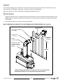
NOTE: Sheet metal parts have sharp edges, use caution when handling.
Frame Assembly
Special note prior to frame assembly.
The parts of this frame are designed so that once the frame is assembled and attached to the replace, the face of the
frame will be free of all screw heads protruding outward which would interfere with the facing material being applied to
the frame. Care must be taken during assembly so that all holes in the narrow side of the frame parts face toward the
rear of the replace. Figure 17 shows these holes on side of the frame parts.
Frame assembly instructions.
1. On a large at surface, lay the parts on their narrow end and with the holes mentioned in the special note above,
facing upward. Place 1 upper/lower stud (#4) horizontally. This will become the top-most horizontal stud.
2. Place 2 center studs (#6) perpendicular to, and below the above upper/lower stud. Using the screw holes on the
upper/lower stud as a guide, place each center stud approx 8” on either side of the upper/lower stud center point
so that they are in-line with the screw holes.
3. Use supplied wafer screws (#1) to join the upper/lower stud (#4) and the center studs (#6) together.
4. Position Inner Cross Brace (#5) horizontally along the bottom ends of the 2 center studs (#6) and fasten with wafer
screws to the center-most 2 positions along this cross brace.
5. Position Side Studs (#2) at each end of the assembled frame so that the side studs are perpendicular to the upper/
lower stud and inner cross brace.
6. Position the Lower Cross Brace (#7) between the two side studs and about 6” from the lower ends of the side
studs. Attach each end of the lower cross brace to the side studs with wafer screws. Position this brace so that the
narrow vertical side is facing outward away from the replace as shown in Figure 14.
7. Fasten 2 framing plates (#8) to the outside of each of the 2 side studs (Figure 15) beginning with the lower one.
There must be 16 inches from the top of the lower plate to the top of the upper plate when done. Make sure that the
two holes in each plate face toward the rear of the replace (Figure 15 and Figure 17). Also make sure to position
the plates so that they line up with the framing brackets on the replace (Figure 17).
8. Place and attach the two Outer Side studs (#3) - tab side out (Figure 14 and Figure 16). - at each end of both the
top upper/lower stud and bottom upper/lower stud.
9. Finish the frame assembly by attaching the 2nd upper/lower stud (#4) at the bottom of, and perpendicular to the
side studs.
100001138-50 12 TCWS38D2_301123-48

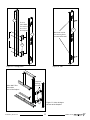
Figure 18: Bend tab out 90 degrees
Attach the Assembled Frame and fireplace to the combustible framing.
Bend out the tabs 90 degrees before inserting the unit into its framed housing “Bend tab out 90 degrees” (Figure 18).
Attach the assembled framing kit to the Fireplace.
Secure the frame assembly to the wood frame through the tabs (Figure 19).
Install Non-Combustible Board
Use drywall screws, #8, to install the non-combustible board.
Fixed Lintel
The lintel on the TCWS38D2 is in a xed
position on the replace and there is no
adjustment to move the lintel toward you or
away from you once the replace has been
located in its nal position. Instead, the
replace itself must be maneuvered so that
the front face of the lintel determines the nal
position of the replace.
The Framing Kit allows for a 1 7/8 inch
adjustment along the Framing Brackets. Use
this range to help determine the front of the
facing material.
The thickness of the facing material, whether
1/2 inch calcium silicate board or a rock
facing must be taken into consideration
before settling on a nal position of the
replace. “Fireplace Facing Allowance” on
page 14.
Framing Kit Adjustment
Figure 19: Attaching metal tab to frame
Figure 20: TCWS38D2 Fixed lintel
100001138-50
13
TCWS38D2_301123-48

This replace is designed to nish
either ush with the facing material
or can be installed with a 4 1/2 inch
recess, see “Figure 11: TCWS38D
Recessed installation details.” on
page 9.
The replace can accommodate
facing material thickness from 1/2
of an inch to 2 1/4 inches if installing
ush.
Care should be taken to correctly
determine the facing material
thickness so that the replace is
positioned so that the front of the
replace is ush with the facing
material.
Facing material must not interfere
with the ability for the door or the
screen to open.
Fireplace Facing Allowance
Range
1 7/8”
Figure 21: Framing bracket.
NON-COMBUSTIBLE
FINISH MATERIAL NON-COMBUSTIBLE
BUILDING MATERIAL MAY NOT
EXTEND PAST THIS POINT
SCREEN
DOOR
Figure 22: Facing edge location.
100001138-50 14 TCWS38D2_301123-48

Hearth Extension
Caution: While a hearth extension is not required and combustible ooring materials
may be brought directly up to the replace, many materials (such as wood ooring) may
not tolerate the radiant heat from this replace, resulting in discoloration, shrinking and
cracking. For this reason, we suggest a non-combustible hearth that is no more than 1”
above the bottom of the replace. If thicker, replace must be raised accordingly.
Caution: Hearth extensions thicker than 1” will interfere with the safety screen and door
frame when opening.
Bottom of replace
Maximum
heigth of 1”
above bottom
of replace
Lintel
Hearth
Extention
Figure 23: TCWS38D2 Hearth extension.
100001138-50
15
TCWS38D2_301123-48

Figure 26:
Valve assembly
components
Figure 25: Junction box wiring
Figure 24: Firebox access panel.
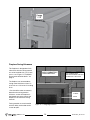
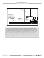
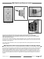
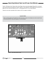
The gas control system is located on the right hand side of the rebox behind an access
panel and the decorative rebox panel (if installed). The replace is operated via a wall
control and a hand held remote control unit.
The wall control is connected to the replace by a 40 ft. communication cable supplied
with the replace.
Installation
1. Place the replace in the desired location.
2. Remove the door from the replace.
3. Remove access panel from right hand side of the rebox (Figure 24).
4. Connect 110 V. AC electrical supply to the wires installed inside the junction box
(Figure 25). The replace is rated at 110 volts, 60Hz, 0.25A. The optional power vent
kit is rated at 115 volts, 60Hz, 1.8A.
The electrical wires can be accessed from both inside and outside the junction box
by removing one of the two small access panels (Figure 25 and Figure 26).
5. Attach the wall switch to the framing in the desired location. (40 ft is supplied with
replace)
6. Route the wall switch control cable (supplied) as required to the wall switch.
7. Attach one end of the wall switch control cable to the wall control (Figure 28), and
the other end to the interface board (Figure 26).
8. Insert the 4 supplied “AA” batteries into the battery pack
of the wall switch (Figure 29).
FIREBOX ACCESS PANEL
INTERFACE BOARD
MODULE
JUNCTION BOX
REGULATOR
BOARD
TRANSFORMER
VACUUM
SWITCH
GAS CONNECTOR
INSIDE ACCESS
PANEL
WALL SWITCH
CONNECTOR
JUNCTION BOX
POWER
VENT
SWITCH
Electrical
Note: Installation must be performed by a qualified
installer, service agency or gas supplier.
9. If not already installed, install the burner
using the instructions supplied with the
burner kit.
10. Turn on the gas supply and check that all
connections are tight and leak free.
11. Turn on gas and electrical supplies.
100001138-50 16 TCWS38D2_301123-48

Figure 29: Wall switch - battery side.
Figure 28: Wall switch - interface side
TO FIREPLACE
Wall Switch and Remote Control
Figure 27: Town & Country
wall switch
Instructions for linking the wall switch to the remote control handset can be found page
39(Bluetooth Wall Switch) and page 40 (Basic Wall Switch) of this manual and in the User manual
that came with this Fireplace.
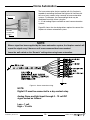
If the wall switch is being connected to a Home Automation system, two cables will be used; the top cable
will go from the wall switch to the replace and the bottom cable will go from, the wall switch to the Home
Automation system Figure 30 .
If not using a Home Automation system, only the upper cable will be used to go from the wall switch to the
replace Figure 28.
Wall Switch to IFC Communication Cable Continuity Check
It is important that the continuity of the individual wires encased within the communication cable be checked
before the cable is plugged into both the wall switch and the IFC Module. This will ensure that the cable is
in good condition before the cable is walled in or otherwise covered up. Provided that no staples, screws
or nails accidentally impale the cable during the walling up process, or any cables have otherwise been cut,
the cable itself will be able to be ruled out as a possible cause should trouble shooting the wall switch be
required.
Figure 30: Basic Wall switch -
Interface side.
100001138-50
17
TCWS38D2_301123-48

The NV / PV (Natural Vent / Power Vent) switch (Figure 31) on the interface board (Figure 26) is set accord-
ing to which type of evacuating vent system is present. If the replace is vented without the assistance of a
power vent, the switch must be set to “NV”. If using a power vent, “PV” must be selected.
Follow the instructions provided with the power vent kit for proper installation.
Selecting Natural Vent and Power Vent Modes
Figure 31: Vent mode selection switch.
Important Note:
When switching between PV and NV, the electrical power supply to the replace must be turned off and
the backup batteries removed to properly re-set the module
100001138-50 18 TCWS38D2_301123-48

Figure 32: Complete communication wiring
TO HOME
AUTOMATION
SYSTEM
NOTE:
Digital I/O must be connected to a dry contact relay.
Analog flame and light input through 0 - 10 volt DC
signal scaled as follows:
Low = 1 volt
High = 10 volts
NOTE:
• When a signal has been supplied by the home automation system, the fireplace control will
repeat the signal every 2 hours or until a new command has been received.
• Leave the wall switch on the “Remote” setting when using home automation.
The home automation feature supplied with this replace is
capable of controlling the ame and light on/off function with
the use of a dry contact relay common to home automation
systems. Furthermore, the ame and light level may be
modulated from high to low using the
0 - 10 volt analog output available on most home automation
systems.
Figure 33 shows the wire designations required to connect the
replace to a home automation system.
Home Automation
Figure 33: Home automation wiring.
TO FIREPLACE
100001138-50
19
TCWS38D2_301123-48

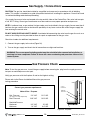
SUPPLY
PRESSURE
MANIFOLD
PRESSURE
CAUTION: The gas line should be installed by a qualied service person in accordance with all building
codes. This section is intended as a guide for qualied technicians installing this appliance. Consult local and
/ or national building codes before proceeding.
Gas supply line access holes are located at the top and left sides of the Control Box. Gas valve inlet accepts
a 3/8" N.P.T. tting. Correct gas line diameter must be used to assure proper operation and pressure.
NOTE: A sediment trap, as per national fuel gas code, must be installed in the gas supply line no more than 6
feet from the gas control valve to minimize the possibility of any loose scale or dirt within the gas supply line
from entering the control valve.
DO NOT HARD PIPE GAS LINE TO VALVE. A method of disconnecting the valve from the gas line such as a
union or are tting must be provided to allow for repair or replacement of the gas valve.
Check local codes for additional requirements.
1. Connect the gas supply to the valve (Figure 26).
2. Turn on the gas supply and check that all connections are tight and leak free.
Correct gas pressure requirement:
Natural Gas Propane
Min. Pressure 5.0" WC 12.5" WC
(For purpose of input adjustment)
Max. Pressure 13.9" WC 13.9" WC
Manifold Pressure
Maximum 3.5" WC 10" WC
Minimum 1.6" WC 6.4" WC
Note: To test the gas pressure, turn off the gas supply before removing the plug from the supply pressure
test port or manifold pressure test port.
Verify gas pressures with the replace lit and on the highest setting.
Please refer to the Burner Installation Manual for gas pressure
testing procedure.
Gas Supply / Connections
Gas Pressure Check
WARNING: The access panel including gasket must be reinstalled after conversion/installation or
servicing has been completed. Failure to do so will cause overheating and premature failure of the
control system.
Figure 34: Test ports.
100001138-50 20 TCWS38D2_301123-48
Page is loading ...
Page is loading ...
Page is loading ...
Page is loading ...
Page is loading ...
Page is loading ...
Page is loading ...
Page is loading ...
Page is loading ...
Page is loading ...
Page is loading ...
Page is loading ...
Page is loading ...
Page is loading ...
Page is loading ...
Page is loading ...
Page is loading ...
Page is loading ...
Page is loading ...
Page is loading ...
Page is loading ...
Page is loading ...
Page is loading ...
Page is loading ...
Page is loading ...
Page is loading ...
Page is loading ...
Page is loading ...
-
 1
1
-
 2
2
-
 3
3
-
 4
4
-
 5
5
-
 6
6
-
 7
7
-
 8
8
-
 9
9
-
 10
10
-
 11
11
-
 12
12
-
 13
13
-
 14
14
-
 15
15
-
 16
16
-
 17
17
-
 18
18
-
 19
19
-
 20
20
-
 21
21
-
 22
22
-
 23
23
-
 24
24
-
 25
25
-
 26
26
-
 27
27
-
 28
28
-
 29
29
-
 30
30
-
 31
31
-
 32
32
-
 33
33
-
 34
34
-
 35
35
-
 36
36
-
 37
37
-
 38
38
-
 39
39
-
 40
40
-
 41
41
-
 42
42
-
 43
43
-
 44
44
-
 45
45
-
 46
46
-
 47
47
-
 48
48


Town & Country Fireplaces WS38 Installation guide
- Category
- Fireplaces
- Type
- Installation guide
Ask a question and I''ll find the answer in the document
Finding information in a document is now easier with AI
Related papers
-
Town & Country Fireplaces WS54 Installation guide
-
-
-
-
-
-
-
-
-
Other documents
-
 Regency Fireplace Products HZ54E Owner's manual
-
 Regency Fireplace Products Ultimate U900E Owner's manual
-
 Regency Fireplace Products Ultimate U1500E Owner's manual
-
 Regency Fireplace Products Ultimate U900E Owner's manual
-
 Regency Fireplace Products Horizon HZ40E Owner's manual
-
 Regency Fireplace Products HZ54E Owner's manual
-
 Regency Fireplace Products Ultimate U1500E Owner's manual
-
 Regency Fireplace Products HZ42STE Owner's manual
-
 Regency Fireplace Products Horizon HZ40E Owner's manual
-
 Regency Fireplace Products CitySeries New York View 40 Owner's manual


