Page is loading ...

MODEL:
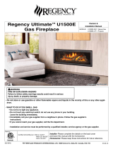
TCWS.54OD SERIES C w/ screen
TCWS54 OUTDOOR GAS
FIREPLACE INSTALLATION AND
OPERATING INSTRUCTIONS
290823-36 TCWS.54 OD W SCREEN 100005095
INSTALLER: Leave this manual with the appliance.
CONSUMER: Retain this manual for future reference.
Visit www.townandcountryfireplaces.net for the most recent version of this manu36
WARNING: If the information in these
instructions is not followed exactly, a re
or explosion may result causing property
damage, personal injury or death.
DANGER: If you smell gas:
1. Shut off gas to the appliance
2. Extinguish any open ame.
3. If odor continues, keep away from the
appliance and immediately call your gas
supplier or re department.
WARNING: Do not store or use gasoline or other
ammable vapors and liquids in the vicinity of
this or any other appliance.
An LP-cylinder not connected for use shall
not be stored
WARNING: Improper installation, adjustment,
alteration, service or maintenance can cause
injury or property damage. Read the installa-
tion, operating and maintenance instructions
thoroughly before installing or servicing this
equipment.
CARBON MONOXIDE HAZARD
This appliance can produce carbon
monoxide which has no odor.
Using it in an enclosed space can
kill you.
Never use this appliance in an
enclosed space such as a camper,
tent, car or home.
SERIAL #
Installation and service must be performed
by a qualied installer, service agency or the
gas supplier.
WARNING:
For Outdoor Use Only

Table of Contents
HOT GLASS WILL CAUSE
BURNS.
DO NOT TOUCH GLASS UNTIL
COOLED.
NEVER ALLOW CHILDREN TO
TOUCH GLASS.
!
DANGER
Table of Contents
Table of Contents ...................................................................... 2
Caution ...................................................................................... 3
Safety ........................................................................................ 3
Important Note for the Commonwealth of Massachusetts ....... 4
This Fireplace Is Intended For Outdoor Use Only! .................... 5
Propane Conversion .................................................................. 6
Fireplace Dimensions ................................................................ 8
Minimum Clearances to Combustible Material ......................... 8
Mantel ClearanceChart ...................................................... 8
Installation Requirements .......................................................... 9
Window Frame Removal ........................................................... 9
Standoffs ................................................................................. 10
Locating The Fireplace ............................................................ 10
Framing and Finishing ............................................................. 11
Steel Stud Framing Kit Dimensions ................................. 11
Minimum Combustible .................................................... 12
Framing Dimensions ........................................................ 12
Non-Combustible Board Detail ........................................ 12
Non-Combustible Recessed Installation Detail ............... 12
Steel Stud Framing Kit ............................................................ 13
Frame assembly ............................................................... 14
Screen Installation ................................................................... 16
Honeywell Control Valve Plumbing and Electrical ................... 17
Installation ........................................................................ 17
Gas Supply .............................................................................. 18
Gas Pressure Check ................................................................ 18
Correct gas pressure requirement.................................... 18
Venting ..................................................................................... 19
Roof Termination Venting Chart ............................................... 19
Ceiling Opening ................................................................ 20
Ceiling Firestop ................................................................ 20
Vent Pipe .......................................................................... 20
Roof Support Bracket ...................................................... 20
Roof Vent Terminal ........................................................... 21
Vent Terminal Clearance .......................................................... 22
Vent Pipe Sealant .................................................................... 23
Vent Restrictor Adjustment ..................................................... 24
Firebox Panels Installation ...................................................... 25
Lighting Instructions ................................................................ 26
First Fire ................................................................................... 26
Maintenance ............................................................................ 27
Glass Panel: ..................................................................... 27
Annual Inspection: ............................................................ 27
Periodically: ...................................................................... 27
TCWS.54CODE Replacement Parts ........................................ 28
Honeywell Control System Replacement Parts ...................... 29
Wiring Diagram ........................................................................ 30
Roof Termination Kit ................................................................ 31
Vent Pipe Dimensions ............................................................. 32
Vent Offset Chart ..................................................................... 33
Quick Panel Removal for Valve Service .................................. 34
Rating Label Location ............................................................. 35
WARNING: This product
can expose you to chemicals
including ceramic bers,
which are known to the State
of California to cause cancer, and carbon
monoxide, which is known to the State of
California to cause birth defects or other
reproductive harm.
For more information go to
www.P65Warnings.ca.gov.
This warning is applicable to all
Pacific Energy Fireplace Products
2
100005095 TCWS.54OD W SCREEN_290823-36

FOR YOUR SAFETY - Do not install or operate your Town & Country re-
place without rst reading and understanding this manual. Any installation or
operational deviation from the following instructions voids the Town & Country
Fireplaces Warranty and may prove hazardous.
This appliance and its individual shut off valve must be disconnected from gas
supply piping system during any pressure testing of that system at test pres-
sures in excess of 1/2 psig (3.5 kPa).
This appliance must be isolated from the gas supply piping system by closing
its individual manual shut off valve during any pressure testing of the gas sup-
ply piping system at test pressures equal to or less than 1/2 psig (3.5 kPa).
Note: When lit for the rst time, the appliance will emit a slight odour for a
couple of hours. This is due to the curing of paints, sealants and lubricants
used in the manufacturing process. This condition is temporary. Open doors
and windows to ventilate area. Smoke and fumes caused by the curing pro-
cess may cause discomfort to some individuals.
Do not use the replace if any part has been under water. Immediately call a
qualied service technician to inspect the replace and to replace any part of
the control system and any gas control which has been under water.
Due to high temperatures, this gas appliance should be located out of trafc and away from furniture and draperies.
Children and adults should be alerted to the hazards of high surface temperatures and should stay away to avoid burns
or clothing ignition.
Young children should be carefully supervised when they are in the same room as the appliance.
Clothing or other ammable material should not be placed on or near the appliance.
Any grill, panel or door removed for servicing the unit must be replaced prior to operating. Failure to do so may create a
hazardous condition.
Installation and repair should be done by a qualied service person. The appliance should be inspected before use and
at least annually by a professional service person. More frequent cleaning may be required due to excessive lint from
carpeting, bedding material, etc. It is imperative that control compartments, burners and circulating air passageways of
the appliance be kept clean.
It is our policy that no responsibility is assumed by the Company or by any of its employees or representatives for any
damages caused by an inoperable, inadequate, or unsafe condition which is the result, either directly or indirectly, of any
improper operation or installation procedures.
This appliance must not be connected to a chimney ue serving a separate solid fuel burning appliance.
Safety
We recommend that our gas hearth
products be installed and serviced
by professionals who are certied
in the United States by the National
Fireplace Institute® (NFI) as NFI
Gas Specialists
Caution
3100005095TCWS.54OD W SCREEN_290823-36

Important Note for the Commonwealth of Massachusetts
From Massachusetts Rules and Regulations 248 CMR 5.08:
(a) For all side wall horizontally vented gas fuelled equipment installed in every dwelling, building or structure used in whole or in part for residential
purposes, including those owned or operated by the Commonwealth and where the side wall exhaust vent termination is less than seven (7) feet above
nished grade in the area of the venting, including but not limited to decks and porches, the following requirements shall be satised.
1. INSTALLATION OF CARBON MONOXIDE DETECTORS. At the time of installation of the side wall horizontal vented gas fuelled equipment, the
installing plumber or gas tter shall observe that a hard wired carbon monoxide detector with an alarm and battery back-up is installed on the oor level
where the gas equipment is to be installed, in addition, the installing plumber or gas tter shall observe that a battery operated or hard-wired carbon
monoxide detector with an alarm is installed on each additional level of the dwelling, building or structure served by the side wall horizontal vented gas
fuelled equipment. It shall be the responsibility of the property owner to secure the services of qualied licensed professionals for the installation of
hard-wired carbon monoxide detectors.
a. In the event that the side wall horizontally vented gas fuelled equipment is installed in a crawl space or an attic, the hard-wired carbon monoxide
detector with alarm and battery back-up may be installed on the next adjacent oor level.
b. In the event that the requirements of this subdivision cannot be met at the time of completion of installation, the owner shall have a period of thirty
(30) days to comply with the above requirements; provided, however, that during said thirty (30) day period, a battery operated carbon monoxide detec-
tor with an alarm shall be installed.
2. APPROVED CARBON MONOXIDE DETECTORS. Each carbon monoxide detector as required in accordance with the above provisions shall
comply with NFPA 720 and be ANSI/UL 2034 listed as IAS certied.
3. SIGNAGE. A metal or plastic identication plate shall be permanently mounted to the exterior of the building at a minimum height of eight (8) feet
above grade directly in line with the exhaust vent terminal for the horizontally vented gas fuelled heating appliance or equipment. The sign shall read, in
print size no less than one-half (1/2) inch in size, “GAS VENT DIRECTLY BELOW. KEEP CLEAR OF ALL OBSTRUCTIONS”.
4. INSPECTION. The state or local gas inspector of the side wall horizontally vented gas fuelled equipment shall not approve the installation unless,
upon inspection, the inspector observes carbon monoxide detectors and signage installed in accordance with the provisions of 248 CMR 5.089(2)(a) 1
through 4.
(b) EXEMPTIONS. The following equipment is exempt from 248 CMR 5.089(2)(a) 1 through 4.
1. The equipment listed in Chapter 10 entitled “Equipment Not Required To Be Vented” in the most current edition of NFPA 54 as adopted by the
Board; and
2. Product Approved side wall horizontal vented gas fuelled equipment installed in a room or structure separate from the dwelling, building or struc-
ture used in whole or in part for residential purposes.
(c) MANUFACTURER REQUIREMENTS – GAS EQUIPMENT VENTING SYSTEM PROVIDED. When the manufacturer of Product Approved side
wall horizontally vented gas equipment provides a venting system design or venting system components with the equipment, the instructions provided by
the manufacturer for installation of the equipment and the venting system shall include:
1. Detailed instructions for the installation of the venting system design or the venting system components; and
2. A complete parts list for the venting system design or venting system.
(d) MANUFACTURER REQUIREMENTS – GAS EQUIPMENT VENTING SYSTEM NOT PROVIDED. When the manufacturer of a Product Approved
side wall horizontally vented gas fuelled equipment does not provide the parts for venting the fuel gases, but identies “special venting systems”, the fol-
lowing requirements shall be satised by the manufacturer.
1. The referenced “special venting system” instructions shall be included with the appliance or equipment installation instructions; and
2. The “special venting systems” shall be Product Approved by the Board, and the instructions for that system shall include a parts list and detailed
installation instructions.
(e)) A copy of all installation instructions for all Product Approved side wall horizontally vented gas fuelled equipment, all venting instructions, all parts
lists for venting instructions, and/or all venting design instructions shall remain with the appliance or equipment at the completion of the installation.
4
100005095 TCWS.54OD W SCREEN_290823-36

WARNING: Solid fuels
should not be burned in
this appliance.
Warning:
This appliance is only for use
with the type of gas indicated
on the rating plate. This ap-
pliance is not convertible for
use with other gases, unless
a certied kit is used.
• The replace must be located inside of a weatherproof enclosure.
• Flashing must be installed around the replace opening in accordance
with local building codes in order to prevent moisture from entering the
enclosure.
• A drip pan (not supplied with the unit) must be installed under the
replace and be provided with a means of draining.
• Care must be taken to select materials and building practices which will
protect the enclosure and replace from exposure to moisture.
• Not for use with a power vent.
This Fireplace Is Intended For Outdoor Use Only!
5100005095TCWS.54OD W SCREEN_290823-36

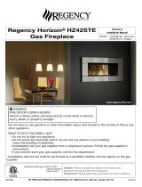
Figure 1: Burner tray removal. Figure 2: Removing the orice.
WARNING
This conversion kit shall be installed by a qualified service agency in accordance with the
manufacturer's instructions and all applicable codes and requirements of the authority having
jurisdiction.
If the information in these instructions is not followed exactly, a fire, explosion or production of
carbon monoxide may result causing property damage, personal injury or loss of life.
The qualified service agency is responsible for the proper installation of this kit.
The installation is not proper and complete until the operation of the converted appliance is
checked as specified in the manufacturer's instructions supplied with the kit.
If the unit is to be used with propane, convert as follows using the components supplied with the
TCWS 54 Propane Conversion Kit p/n TCWS54DLPKIT which includes Propane orifice and Conversion
Label.
CAUTION
The gas supply and electrical power shall be shut off before proceeding with the conversion.
Note:
Factory supplied components must be used to ensure correct input. After conversion, conrm proper manifold pressure.
Propane Conversion
1. If installed remove the glass media from the burners.
2. If installed remove the burner tray from the manifold brackets (Figure 1).
3. Remove burners.
4. Using a 1/2” wrench, undo the natural gas burner orice (Figure 2). Apply a small amount of pipe joint compound to
the threads of the propane burner orice (marked 1.70mm) to ensure a good seal, before screwing it into the tting.
6
100005095 TCWS.54OD W SCREEN_290823-36

With a 7/16” wrench loosen the pilot head on the pilot assembly (Figure 1).
Slide the pilot adjustment band over and ensure that the hole in the orice band is showing (Figure 2).
Update Propane Conversion Sticker with date and name after conversion is nished (Figure 3).
THIS FIREPLACE IS DESIGNED
FOR USE WITH A P.S.E. PILOT,
DO NOT USE ANY OTHER
PILOT WITH YOUR OUTDOOR
FIREPLACE.
For complete conversion valve installation instructions, refer
to the instruction book included in the SIT conversion kit.
WARNING: Both the control box shield and the access panel must be reinstalled after conversion/
installation or servicing has been completed. Failure to do so will cause overheat ing and premature
failure of the control system.
Figure 1: Loosen Pilot Head - PSE.
Figure 2: Natural gas position -PSE. Figure 3: Liquid propane position - PSE.
Adjustment Band - NG Adjustment Band -
Hole showing - LP
7100005095TCWS.54OD W SCREEN_290823-36

29 3/4"
24"
4“
*
CEILING
ADJACENT WALL
OR MANTEL SUPPORT
6”
COMBUSTIBLE FLOOR
COMBUSTIBLE HEARTH
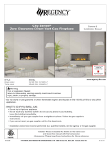
Figure 5: Mantel clearances.
Figure 6: Mantel.
* MANTEL CLEARANCE
A 9”
B 6”
C 3”
** MANTEL DEPTH
D 12”
E 6 3/4”
F 1 1/2”
Mantel Clearance
Chart
UNIT MAY BE RECESSED UP TO 6” WITH
NONCOMBUSTIBLE MASONRY TYPE MATERIAL
Minimum Clearances:
Side standoffs ....................................................... 0 in. (0 mm)
Back standoffs ...................................................... 0 in. (0 mm)
Top standoffs ........................................................0 in. (0 mm)
Bottom of appliance .............................................. 0 in. (0 mm)
Adjacent side wall ................................................. 4 in. (102 mm)
Ceiling to appliance ............................................24 in. (610 mm)
*Mantel to appliance .................. ..........See Figure #6
**Maximum Mantel extension .. ..........See Figure #6
Mantel support ...................................................... 4 in. (102 mm)
Vertical vent pipe ..........................................1 3/4" in. (45 mm)
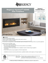
74 3/4”
18”
55”
74 3/4”
53 7/8”
25”
13 5/8”
29 3/4”
28 5/8”
36 7/8” 37 7/8”
35 3/4”
Figure 4: TCWS.54 OD with Screen dimensions.
MAY USE COMBUSTIBLE
FACING MATERIAL IN THIS AREA
NON-COMBUSTIBLE
FINISH MATERIAL
SEE FIG #8 & 9
NON-COMBUSTIBLE ZONE.
DO NOT INSTALL ANY COMBUSTIBLE MATERIAL,
ELECTRICAL WIRING OR GAS PLUMBING IN THIS
AREA.
COMBUSTIBLE FRAMING AND
FINISH WALL ABOVE STANDOFFS
STANDOFFS
STEEL FRAMING
FIREPLACE FRONT
TOP OF LINTEL BAR
A
B
C
D
E
F
8
100005095 TCWS.54OD W SCREEN_290823-36
Fireplace Dimensions
Minimum Clearances to Combustible Material

Warning: Turn off the replace, and allow ample time for the unit to cool before proceeding.
Caution: The ceramic glass is very fragile, and should be handled with care.
The window frame is held in place by two spring-loaded latches that are operated by a one-piece latch handle.
1. Remove the TC Finishing Touch Trim Kit from the window frame. (If installed)
2. Using a screwdriver or other similar object, push against the notch in the top of the latch and grab the bottom of the
latch handle as it protrudes. Lift handle until latch hook disengages (Figure 7) & (Figure 8). Repeat for other side while
holding glass so it does not tip out.
3. Tilt the top of the window frame out to clear the top edge of the unit. Grasp the sides of the frame and lift up and out
to disengage from its bottom track.
4. Place the window frame in a safe place to avoid damage.
5. Re-assemble in reverse order. Latch handle should snap into place and be ush with window frame when engaged
correctly.
6. Reinstall Trim Kit if required.
TIP:
To ensure glass is properly latched, grasp the top left and right
sides of the glass frame, under moderate pressure it should pull
forward and return to original position evenly on both sides.
HANDLE
Figure 7: Accessing handle. Figure 8: Handle.
The Town & Country Fireplace installation and venting must conform to the current CAN/CGA-B149 installation code (in
Canada) or the current National Fuel Gas Code, ANSI Z223.1 (in the USA), and approved per local codes. Only qualied
(licensed or trained) personnel should install this product.
In the state of Massachusetts, only a licensed Plumber and Gas Fitter may install this product.
9100005095TCWS.54OD W SCREEN_290823-36
Installation Requirements
Window Frame Removal

The standoffs are shipped loose inside the replace and must be installed on the top and the side of the replace as
shown in (Figure 9). Do this once the replace is on site and in position.
In planning the installation for the replace, it is necessary to determine where the unit is to be installed, location of vent
system and where gas supply piping may be plumbed. Various installations are possible, such as, into an existing wall,
a corner, a built-in wall or a wall projection (Figure 10). Due to high temperatures, do not locate this replace in areas of
high trafc or near furniture or draperies.
The minimum clearances from the replace to combustible surfaces must be adhered to and are shown in Figure 6 & 7.
Figure 10: TCWS54CODE Possible locations.
EXAMPLES OF COMMON LOCATIONS
SEE FIG #15 FOR DIMENSIONS
TOP STANDOFFS
SIDE
STANDOFF
(THIS SIDE ONLY)
Figure 9: TCWS54CODE standoffs.
HANDLE
CONTROL
BOX
10
100005095 TCWS.54OD W SCREEN_290823-36
Locating The Fireplace
Standoffs

Note: The fireplace should be in place
and venting installed before framing
in or building an enclosure around the
unit.
The Town & Country replace must be
framed in as described below or totally
enclosed with non-combustible material,
such as facing brick.
Determine the total thickness of facing
material to be used. The framing Kit is
adjustable, and will allow for 3/8” to 1-3/8”
nishing surface to be ush with the front
of the unit. If preferred, additional masonry
type non-combustible material can be
installed above and to the sides up to 6
inches forward of the appliance.
*The finishing material must not inter-
fere with glass frame access.*
A Steel Stud Framing Kit is supplied with
the replace and must be used unless the
replace is totally enclosed with non-com-
bustible material. Assemble the framing kit
as per the instructions on pages 11 - 13
of this manual. Attach the steel frame to
the replace once the replace is in its
nal position. Set the depth and secure
the steel frame to the framing brackets on
each side of the unit. Ensure that the studs
are set back far enough to allow for thick-
ness of nishing surface.
The sides, back and top of the replace
can be framed in up to the steel studs and
the replace standoffs using conventional
lumber. Consult local building codes for
specic requirements.
Due to high temperatures, non-combusti-
ble backer board, such as cement board
or its equivalent, must be used to sheet
in the front of the replace, extending
12" below, 12” above and 9 5/8" to the
side of the framing edge bars (Figure 12).
Standard sheetrock (dry wall) may be used
beyond this.
If the backer board is not to be nished
with other non-combustible material
such as tiles, it is recommended that the
instructions in (Figure 14) be followed
closely.
Fabricate and install appropriate ashing
to local building code.
Note: Installing unit without flashing
installed will void the warranty
Note: Provide proper drainage to divert
water underneath the unit
Chase Insulation: When installing this
replace against a non-insulated exterior
wall or chase, it is recommended that
the outer walls be insulated to the same
degree as other exterior walls. Do not
place replace directly against the insu-
lation. Cover the insulation and plastic
vapour barrier with a solid surface, such
as dry wall (sheetrock). Consult local
codes. Do not insulate or use plastic
vapour barrier within the framing kit.
CAUTION: SEE (Figure 14) BEFORE
PROCEEDING.
76”
55”
Figure 11: TCWS54CODE with supplied steel frame.
ALL OTHER FRAMING CAN
BE DONE WITH
CONVENTIONAL LUMBER
NON-COMBUSTIBLE ZONE. DO NOT INSTALL ANY
COMBUSTIBLE MATERIAL, ELECTRICAL WIRING,
INSULATION, PLASTIC VAPOR BARRIER OR GAS
PLUMBING WITHIN THE STEEL STUD FRAMING
Steel Stud Framing Kit Dimensions
(Supplied with fireplace)
11 100005095TCWS.54OD W SCREEN_290823-36
Framing and Finishing

MAXIMUM FACING DEPTH
IF FINISHING THE WALL ABOVE THE
UNIT WITH PAINT, THE FRAMING
KIT SHIPPED WITH THE UNIT SHOULD
BE DISCARDED.
IT IS RECOMMENDED TO USE FULL
SHEETS OF CALCIUM SILICATE
BOARD OR ITS EQUIVALENT AND
FULL LENGTH METAL STUDS TO
FINISH AND FRAME AROUND THE
UNIT.
FOLLOW THE MANUFACTURERS
MOUNTING AND FINISHING
INSTRUCTIONS CLOSELY.
NOTE: IT IS RECOMMENDED TO
PREDRILL MOUNTING HOLES IN THE
BOARD PRIOR TO SECURING TO THE
FRAMING. THIS WILL PREVENT THE
BOARD FROM CRACKING.
NON-COMBUSTIBLE
BOARD
Figure 13: Recessed installation detail. Figure 14: Non combustible calcium
silicate board.
Non-Combustible
Recessed Installation
Detail
Minimum Combustible
Framing Dimensions
Figure 15: WS54 OD w Screen framing dimensions.
76 1/4"
55 1/4"
76 1/4"
23 1/2"
to
24 1/2”
11 5/16"3/8" - 1 3/8”
84" to 85 1/2”
33 3/8"
119" -
121”
76"
47 1/8"
STEEL STUDS
NON-COMBUSTIBLE
MASONRY TYPE MATERIAL
NON-COMBUSTIBLE
BOARD
12”
9 5/8”
12”
Figure 12: TCWS54CODE Non-combustible board dimensions.
Non-Combustible Board Detail
NON-COMBUSTIBLE
MATERIAL MUST EXTEND
12" ABOVE, 9 5/8" TO THE
SIDES AND 12” BELOW THE
FRAMING EDGES.
NON-COMBUSTIBLE
BOARD
12
100005095 TCWS.54OD W SCREEN_290823-36

1
2
3
4
5
6
7
8
Figure 16: TCWS54CODE Framing kit parts.
Each Kit Contains:
Item Part # Description Qty.
1 5049.9912 SCREW, WAFER #8 x 1/2 Pkg
40
2 8293.4 STUD, SIDES 55” L 2
3 8293.2 STUD, OUTER SIDES 55” L 2
4 8293 STUD, UPPER/LOWER
75 1/4” L
2
5 8293.6 INNER CROSS BRACE
56 5/8” L
1
6 8293.8 STUD, CENTER 25” L 3
7 8293.9 LOWER CROSS BRACE
56 5/8” L
1
13 100005095TCWS.54OD W SCREEN_290823-36
Steel Stud Framing Kit

1. On a at surface, lay one 76” (#4) stud on its end and at the top of your working area. This will be the top most
horizontal stud.
2. Position all three 25” studs (#6) vertically with the center stud aligning with the center of the above (#4) horizontal
stud. Use supplied screws to afx the tops of the vertical studs to the horizontal stud.
3. Position two - 55” studs (#2) on either side of the three vertical studs (#6), centering them so that they are
approximately 56” from each other while being evenly centered in relation to the top (#4) stud. Use supplied screws
to afx the tops of these studs to the top horizontal stud.
4. Position stud (#5) horizontally along the bottom ends of the three 25” (#6) vertical studs while aligning the ends of
this stud with the two 55” (#2) studs. This stud has an angled bottom which makes one side of the stud higher on
one edge than the other. The higher edge will face toward the replace once assembled. Use supplied screws to afx
this stud to all ve vertical studs (#2) & (#6).
5. Position stud (#7) horizontally approximately 12” from the bottom of the two vertical studs (#2). Make sure that the
slot side is facing up. Afx the ends of this stud to the vertical (#2) studs.
6. With the tabs bent outward, position the two 55” (#3) studs vertically, one at each end of the top most horizontal stud
(#4) and afx.
7. Place the nal 76” (#4) horizontal stud at the bottom of the assembly and afx to the four vertical studs.
8. Turn the assembly over and afx the remaining screws to the other side of the frame.
Frame assembly
Figure 17: TCWS54CODE Steel frame assembled.
2
2
33
4
4
5
6
7
FRONT VIEW (slightly angled)
BEND OUT FRAMING
TABS TO FRONT
WIDE FACE
FORWARD
SCREW INTO
SIDE
SLOTS UP
LONG EDGE UP
66
14
100005095 TCWS.54OD W SCREEN_290823-36

Figure 18: Framing bracket fastening points.
Figure 19: Framing tabs bent out.
1. Attach the assembled frame to the fireplace
• Bend out the framing mounting tabs 90 degrees
before inserting the unit into its framed housing
(Figure 19).
• Align the assembled frame between the replace
framing brackets (Figure 18).Install screws at the
fastening points. Set the depth of the Steel frame
based on the desired depth of facing and tighten
the screws.(There are access holes in the outer
side studs (3) if needed).
2. Secure to Existing Framing
• Using the Framing Mounting Tabs, secure the
frame assembly to the wood frame through the
holes in the tabs.
The lintel on the TCWS 54 Outdoor w/ screen is in a xed position on the replace and there is no adjustment
to move the lintel toward you or away from you once the replace has been located in its nal position.
Instead, the replace itself must be manoeuvered so that the front face of the lintel determines the nal
position of the replace.
The Framing Kit is adjustable and allows for a 1inch of adjustment in mounting depth along the Framing
Brackets. Use this adjustability to help with the desired installation of the front facing material.
The thickness of the facing material, could be 3/8” inch calcium silicate board or a 1 3/8” rock facing and must
be taken into consideration before settling on a nal position of the replace.
15 100005095TCWS.54OD W SCREEN_290823-36

This replace may be recessed up to a
maximum depth of 6”, this recess must
be constructed from non combustible
material. The space between the outside
lintels and the rebox must be com-
pletely free of any obstructions or debris
and the window with trim tted must be
able to move freely. No building material
is permitted to protrude past the lintel
bars attached to the replace under ANY
circumstance.
FRAMING
EDGES
GLASS
FRAME
NON COMBUSTIBLE
FINISH MATERIAL Figure 20: Non-combustible facing area.
Install Non-Combustible Board
(not supplied)
Screen Installation
1. Install the screen with the tabs down and on the back. Wth the Screen tilted towards you at the top, insert
the tabs into the two slots located in the bottom section of the Lintel.
2. Tilt the screen into place until it contacts the magnets and is held in place.
Insert the tab into the Slot
in Lintel
Figure 21: Screen Tab install.ai Figure 22: Screen Magnets.ai
16
100005095 TCWS.54OD W SCREEN_290823-36

Honeywell Control Valve Plumbing and Electrical
The gas control system is located on the right
hand side of the rebox behind an access panel
and the decorative rebox panel (if installed).
The replace is operated via a wall switch.
The wall control is connected to the replace by
a 14-2 AWG wire, not supplied with the replace.
Installation
1. Place the replace in the desired location.
2. Remove the window from the replace.
3. Remove access panel from right hand side
of the rebox (Figure 23).
4. Remove the cover from the electrical box
(Figure 24).
5. Run one 110 V. AC switched electrical
supplies to the control box and connect to
the transformer (Figure 25). The replace
operates on 24V AC supplied by a
transformer rated at 110 volts, 60Hz. See
wiring diagram on page 29 for correct
connections on terminal block.
6. Connect the gas supply to the valve
(Figure 26).
ACCESS PANEL
Figure 23: Access panel location.
ELECTRICAL
BOX COVER
Figure 24: Electrical box cover.
TERMINAL BLOCK,
ELECTRICAL
CONNECTIONS
Figure 25: Electrical connections.
GAS INLET
Figure 26: Gas inlet.
17 100005095TCWS.54OD W SCREEN_290823-36

Gas Pressure Check
Correct gas pressure requirement
Natural Gas Propane
Min. Pressure 5.0" WC 12.5" WC
(For purpose of input adjustment)
Max. Pressure 13.9" WC 13.9" WC
Manifold Pressure
Maximum 3.8" WC 11" WC
Minimum 2.1" WC 5.5" WC
Note: To test the gas pressure, turn off the gas supply before removing the
plug from the supply pressure test port or manifold pressure test port.
Verify gas pressures with the replace lit and on the highest setting.
Please refer to the Burner Installation Manual for gas pressure testing
procedure.
Figure 27: Test ports.
SUPPLY
PRESSURE
MANIFOLD
PRESSURE
Caution: The gas line should be installed by a qualied service person in accordance with all building codes. This sec-
tion is intended as a guide for qualied technicians installing this appliance. Consult local and/or national building codes
before proceeding.
• Gas supply line access holes are located at the top and left sides of the Control Box. Gas valve inlet accepts a 3/8"
N.P.T. tting. Correct gas line diameter must be used to assure proper operation and pressure.
• The replace has an input rate of 54,900 BTU/HR on both Natural Gas and Propane.
• NOTE: A sediment trap, as per national fuel gas code, must be installed in the gas supply line no more than 6
feet from the gas control valve to minimize the possibility of any loose scale or dirt within the gas supply line
from entering the control valve.
• DO NOT HARD PIPE GAS LINE TO VALVE. A method of disconnecting the valve from the gas line such as a
union or flare fitting must be provided to allow for repair or replacement of the gas valve.
Check local codes for additional requirements.
1. Connect the gas supply to the valve (Figure 26).
2. Turn on the gas supply and check that all connections are tight and leak free.
WARNING: Use EXTREME CAUTION when using soap and water to do a leak test on the valve/
fittings. There are electronics around and below the valve, that can/will be damaged if they
come in contact with water.
WARNING: The access panel including gasket must be reinstalled after conversion/installa-
tion or servicing has been completed. Failure to do so will cause overheating and premature
failure of the control system.
18
100005095 TCWS.54OD W SCREEN_290823-36
Gas Supply

Before installing venting for this unit, the installer should read these instructions to insure that the proper vent congura-
tion has been selected. Use only Town and Country Termination kits #:TCVT.RTA - Roof Termination Kit
Vent system components approved for use with the Town and Country Fireplace are shown on page 21.
Various combinations of vent runs may be used. Refer to (Figure 28) for details. For optimum performance and ame
appearance, keep the vent length to a minimum and limit the number of elbows. Connections between each vent system
component must be tightly joined, secured with sheet metal screws and sealed with high temperature self adhesive tape.
VENT SUPPORTS: A minimum of 1 support every 4’ must be used.
CAUTION: UNDER NO CONDITION SHOULD COMBUSTIBLE MATERIAL BE CLOSER THAN 1 3/4 INCHES FROM
ANY PART OF THE VENT PIPE.
20'
10'
40'
MAX.
48'
4' MAX.
MINIMUM VERTICAL
VENT HEIGHT 10 ft (3m)
If using an elbow,
there must be a
minimum of 18” ( 45cm)
of vertical vent before
installing the elbow.
Figure 28: TCWS54CODE Venting chart.
Various combinations of vent runs may be used.
Refer to (Figure 28) for details. For optimum
performance and ame appearance, keep the
vent length to a minimum and limit the number of
elbows. Connections between each vent system
component must be tightly joined, secured with
sheet metal screws and sealed.
CAUTION:
Under no condition
should combustible
material be closer than
1 3/4 inches from any
part of the vent pipe.
Only 45º elbows can be
used in this vent system.
Maximum number of
elbows is 2.
19 100005095TCWS.54OD W SCREEN_290823-36
Venting
Roof Termination Venting Chart

B
14 1/2"
A
Size of the opening will have to
increase with the pitch of the roof
to ensure a 1 3/4" inch air space
clearance between vent pipe and
combustibles.
Roof Pitch A B
0/12 14 1/2" 7 1/4"
4/12 16 1/2" 8 3/4"
6/12 18" 10"
8/12 19 3/4" 11"
12/12 24" 13 3/4"
Figure 29: Roof opening frame.
Figure 30: Roof support bracket.
Ceiling Opening
1. Determine the exact position of the replace so that the vent pipe is cen-
tered (if possible) between two building framing members. Lay out the vent
system path, minimizing the number of elbows and length of vent. Consult
your local building codes prior to proceeding.
2. Cut and frame a 14 1/2" opening in the oor, ceiling or roof where the vent
system will pass. Size of the opening in the roof may need to be increased
as the pitch of the roof increases. Avoid cutting rafters.
Ceiling Firestop
Where a vent pipe passes through a oor or ceiling, a ceiling restop (TCVT.
THIMA) must be used to retain insulation and maintain proper clearances.
From below, push the ceiling restop through the opening and secure in place.
If the restop is used to penetrate a oor, the outer shield may be trimmed in
length. If the restop penetrates into an attic, leave the shield full length to keep
insulation away from the vent pipe. Additionally, after the vent pipe is in place,
install a storm collar on top of the shield. This will prevent loose insulation from
falling into the area between the vent pipe and the shield.
Vent Pipe
1. Install the rst section of vent
pipe into the collar on top of the
replace. Secure in place with
screws and seal with approved
"High Temperature" self-adhesive
aluminium tape provided.
2. Continue adding vent pipe lengths
up and through the restop(s)
and through the roof. The vent
pipe must extend above the roof
according to the sloped roof pitch
table on page 21.
Seal the vent pipe as per "Vent Pipe
Sealant" section.
Roof Support Bracket
Slip the roof support bracket down
over the vent pipe. Rotate the 90°
brackets to accommodate roof pitch.
Attach the brackets to the roof joists
with nails or building screws. Tighten
the band around the vent pipe and
secure in place with screws.
VENT PIPE
ROOF SUPPORT BRACKET
(TCVT.93915)
20
100005095 TCWS.54OD W SCREEN_290823-36
/