Allen-Bradley 1797-CEC Installation Instructions Manual
- Type
- Installation Instructions Manual
This manual is also suitable for
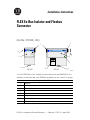
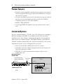
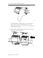
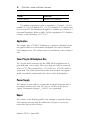
Allen-Bradley 1797-CEC is a FLEX Ex Bus Isolator that provides an IS-compatible mechanism to separate two sections of the backplane allowing IS and non-IS field-device wiring to the same I/O group. It converts hazardous power to IS-safe power to run one side of the bus receiver/transmitter circuitry and IS-safe FLEX Ex backplane power to slave side modules. The device is suitable for use in hazardous areas, and it can be mounted on a DIN rail. It has a protection factor of IP20 and it must not be exposed to the environment.
Allen-Bradley 1797-CEC is a FLEX Ex Bus Isolator that provides an IS-compatible mechanism to separate two sections of the backplane allowing IS and non-IS field-device wiring to the same I/O group. It converts hazardous power to IS-safe power to run one side of the bus receiver/transmitter circuitry and IS-safe FLEX Ex backplane power to slave side modules. The device is suitable for use in hazardous areas, and it can be mounted on a DIN rail. It has a protection factor of IP20 and it must not be exposed to the environment.


-
 1
1
-
 2
2
-
 3
3
-
 4
4
-
 5
5
-
 6
6
-
 7
7
-
 8
8
-
 9
9
-
 10
10
-
 11
11
-
 12
12
-
 13
13
-
 14
14
-
 15
15
-
 16
16
-
 17
17
-
 18
18
-
 19
19
-
 20
20


Allen-Bradley 1797-CEC Installation Instructions Manual
- Type
- Installation Instructions Manual
- This manual is also suitable for
Allen-Bradley 1797-CEC is a FLEX Ex Bus Isolator that provides an IS-compatible mechanism to separate two sections of the backplane allowing IS and non-IS field-device wiring to the same I/O group. It converts hazardous power to IS-safe power to run one side of the bus receiver/transmitter circuitry and IS-safe FLEX Ex backplane power to slave side modules. The device is suitable for use in hazardous areas, and it can be mounted on a DIN rail. It has a protection factor of IP20 and it must not be exposed to the environment.
Ask a question and I''ll find the answer in the document
Finding information in a document is now easier with AI
Related papers
-
Allen-Bradley ControlNet Ex 1797-ACNR15 Installation Instructions Manual
-
-
-
-
-
-
-
-
-
Other documents
-
 Rockwell Automation 1797-CEC Installation Instructions Manual
-
 BARTEC PIXAVI Impact X NC User manual
-
 BARTEC PIXAVI Impact X Hard reset manual
-
 BARTEC PIXAVI Gravity X User manual
-
Rockwell Automation 1797-IE8NF Installation Instructions Manual
-
 Rockwell Automation Allen-Bradley 1794-IB16D User manual
-
Allen Bradley 1794-PS13 User manual
-
 Rockwell Automation Allen-Bradley 1794-IA8I Installation Instructions Manual
-
ProSoft Technology 3170-MBS Installation guide
-
 Rockwell Automation Allen-Bradley ControlNet 1756-CNB User manual


