Page is loading ...

Publication 1797-5.6 - December 2003
Installation Instructions
FLEX Ex 24V dc Non-Isolated Source 4 Output
Module
(Cat. No. 1797-OB4D)
Important User Information
Solid state equipment has operational characteristics differing from those of
electromechanical equipment. Safety Guidelines for the Application, Installation and
Maintenance of Solid State Controls (Publication SGI-1.1 available from your local Rockwell
Automation sales office or online at http://www.ab.com/manuals/gi) describes some
important differences between solid state equipment and hard-wired electromechanical
devices. Because of this difference, and also because of the wide variety of uses for solid
state equipment, all persons responsible for applying this equipment must satisfy
themselves that each intended application of this equipment is acceptable.
In no event will Rockwell Automation, Inc. be responsible or liable for indirect or
consequential damages resulting from the use or application of this equipment.
The examples and diagrams in this manual are included solely for illustrative purposes.
Because of the many variables and requirements associated with any particular installation,
Rockwell Automation, Inc. cannot assume responsibility or liability for actual use based on
the examples and diagrams.
No patent liability is assumed by Rockwell Automation, Inc. with respect to use of
information, circuits, equipment, or software described in this manual.
Reproduction of the contents of this manual, in whole or in part, without written permission
of Rockwell Automation, Inc. is prohibited.
Throughout this manual we use notes to make you aware of safety considerations.
AB Parts

2 FLEX Ex 24V dc Non-Isolated Source 4 Output Module
Publication
1797-5.6 - December 2003
WARNING
Identifies information about practices or circumstances that can cause an explosion in a
hazardous environment, which may lead to personal injury or death, property damage, or
economic loss.
IMPORTANT
Identifies information that is critical for successful application and understanding of the
product.
ATTENTION
Identifies information about practices or circumstances that can lead to personal injury or
death, property damage, or economic loss. Attentions help you:
• identify a hazard
• avoid a hazard
• recognize the consequence
S
HOCK HAZARD
Labels may be located on or inside the drive to alert people that dangerous voltage may
be present.
BURN HAZARD
Labels may be located on or inside the drive to alert people that surfaces may be
dangerous temperatures.
Important User Information
1
2
3
4
5
6
7
Label here or
under here.
8
40231

FLEX Ex 24V dc Non-Isolated Source 4 Output Module 3
Publication
1797-5.6 - December 2003
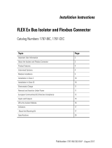
Module Installation
This module must be used with a 1797-TB3 or -TB3S intrinsically safe
terminal base unit.
1. Rotate keyswitch (1) on terminal base unit (2) clockwise to position 7
as required for this type of module. Do not change the position of
the keyswitch after wiring the terminal base unit
2. Make certain the flexbus connector (3) is pushed all the way to the left
to connect with the neighboring terminal base/adapter. You cannot
install the module unless the connector is fully extended.
3. Make sure the pins on the bottom of the module are straight so they
will align properly with the connector in the terminal base unit.
4. Position the module (4) with its alignment bar (5) aligned with the
groove (6) on the terminal base.
5. Press firmly and evenly to seat the module in the terminal base unit.
The module is seated when the latching mechanism (7) is locked into
the module.
ATTENTIO
N
This equipment is considered Group 1, Class A industrial
equipment according to IEC/CISPR Publication 11. Without
appropriate precautions, there may be potential difficulties
ensuring electromagnetic compatibility in other environments
due to conducted as well as radiated disturbance.
This equipment is supplied as “open type” equipment. It must
be mounted within an enclosure that is suitably designed for
those specific environmental conditions that will be present and
appropriately designed to prevent personal injury resulting from
accessibility to live parts. The interior of the enclosure must be
accessible only by the use of a tool. Subsequent sections of this
publication may contain additional information regarding
specific enclosure type ratings that are required to comply with
certain product safety certifications.
AB Parts

4 FLEX Ex 24V dc Non-Isolated Source 4 Output Module
Publication
1797-5.6 - December 2003
6. Make certain that you only connect terminal base units to other
intrinsically safe system modules or adapters to maintain the integrity
of the intrinsically-safe backplane.
7. Remove cap plug (8) and attach another intrinsically safe terminal base
unit to the right of this terminal base unit if required.
Installation in Zone 1
This module must not be exposed to the environment. Provide a suitable
metal enclosure. This module has a protection factor of IP20.
Installation on Zone 22
When the module is installed in Zone 22, the following cabinets must be used:
IVK-ISRPI-V16LC; IVK-ISRPI-V8HYW; or IVK-ISRPI-V8LC. These
cabinets can be purchased from:
Pepperl+Fuchs GmbH
Konigsberger Allee 85-87, D-68307
Mannheim, Germany
Attn: PA Sales Dept.
Kirsten Becker
Telephone +49 776 1298
www.pepperl-fuchs.com
WARNING
This module cannot be used in an intrinsically safe environment
after it has been exposed to non-intrinsically safe signals.
41307

FLEX Ex 24V dc Non-Isolated Source 4 Output Module 5
Publication
1797-5.6 - December 2003
The IS-RPI cabinets (type IVK2-ISRPI-V8LC, IVK2-ISRPI-V8HYW, or
IVK2-ISPRI-V16LC) ensures the basic protection for the intrinsically safe
apparatus of the IS-RPI system for use in Zone 22. It corresponds with
category 3D according to RL 94/9 EG and with the type label marked with
the following information:
Pepperl+Fuchs GmbH
68301 Mannheim
IVK2-ISRPI-V8LC (or IVK2-ISRPI-V8HYW or
IVK2-ISRPI-V16LC)
II 3D IP54 T 70°C
CE
Serial (manufacturing) number
Model
Electrostatic Charge
Protect the system against electrostatic charge. Post a sign near this module:
Attention! Avoid electrostatic charge. For your convenience, a sign which
can be cut out is included in this installation instruction.
Removal and Insertion Under Power
WARNING
These modules are designed so you can remove and insert
them under power. However, take special care when removing
or inserting modules in an active process. I/O attached to any
module being removed or inserted can change states due to its
input/output signal changing conditions.
If you insert or remove the terminal base while backplane power
is on, an electrical arc can occur. This could cause an explosion
in hazardous location installations.
Be sure that power is removed or the area is nonhazardous
before proceeding.
AB Parts

6 FLEX Ex 24V dc Non-Isolated Source 4 Output Module
Publication
1797-5.6 - December 2003
European Communities (EC) Directive Compliance
If this product has the CE mark it is approved for installation within the
European Union and EEA regions. It has been designed and tested to meet
the following directives.
EMC Directive
These products are tested to meet the Council Directive 89/336/EEC
Electromagnetic Compatibility (EMC) as amended by 92/31/EC and
93/68/EEC, by applying the following standards:
• EN 61000-6-4:2001, Electromagnetic Compatibility (EMC) - Part 6-4:
Generic Standard for Industrial Environments (Class A)
• EN 61000-6-2:2001, Electromagnetic Compatibility (EMC) - Part 6-2:
Generic Standards - Immunity for Industrial Environments
• EN61326-1997 + A1-A2, Electrical Equipment For Measurement,
Control, and Laboratory Use - Industrial EMC Requirements
ATEX Directive
These products are tested in conjunction with associated I/O modules to
meet the Council Directive 94/9/EC (ATEX) Equipment and Protective
Systems Intended for Use in Potentially Explosive Atmospheres by applying
the following standards:
• EN50014:1997 + A1-A2, Electrical Apparatus for Potentially
Explosive Atmospheres
• EN50020:1994, Electrical Apparatus for Potentially Explosive
Atmospheres - Intrinsic Safety .i.
• EN50284:1999, Special Requirements for Construction, Test, and
Marking of Electrical Apparatus of Equipment Group II,
Category
1G
• EN50281-1-1:1998 + A1, Electrical Apparatus for Use in the
Presence of Combustible Dust - Part 1-1: Protection by Enclosure

FLEX Ex 24V dc Non-Isolated Source 4 Output Module 7
Publication
1797-5.6 - December 2003
Outputs
Each output can operate a discrete field device.
Do not apply any non-intrinsically safe signals to this module.
When using an intrinsically safe electrical apparatus according to EN50020,
the European Community directives and regulations must be followed.
The channels in this module are electrically connected to each other.
Wiring to a 1797-TB3 or -TB3S Terminal Base Unit
Connect wiring to the terminal base as shown below.
1. Connect the individual output wiring to (+) terminals (0, 4, 8, 12) on
the 0-15 row (A) as indicated in the table below.
flexbus
bus
uC
+V
-V
+
-
power
supply
valve
audible
alarm
solenoid
40069
40068
Row A
Row B
Row C
++++--- -
ch0 ch1 ch2 ch3
+V +V-V -V
0 1 2 3 4 5 6 7 8 9 10 11 12 13 14 15
16 17 18 19 20 21 22 23 24 25 26 27 28 29 30 31 32 33
No connections allowed to terminals 2, 3, 6, 7, 10, 11, 14, 15, 17 to 32, 36, 37, 38, 39,
46, 47, 48, 49
34 35 36 37 38 39 40 41 42 43 44 45 46 47 48 49 50 51
AB Parts

8 FLEX Ex 24V dc Non-Isolated Source 4 Output Module
Publication
1797-5.6 - December 2003
2. Connect the associated output to the corresponding (-) terminal (1, 5,
9, 13) on the 0-15 row (A) for each output as indicated in the table
below.
3. Connect +V dc power to terminal 34 on the 34-51 row (C).
4. Connect -V to terminal 35 on the 34-51 row (C).
5. If continuing power to the next terminal base unit, connect a jumper
from terminal 50 (+V) on this base unit to terminal 34 on the next
base unit.
6. If continuing common to the next terminal base unit, connect a
jumper from terminal 51 (-V) on this base unit to terminal 35 on the
next base unit.
WARNING
Make certain that you power this module with an intrinsically
safe power supply. Do not exceed the values listed in the
specifications for this module.
If you connect or disconnect wiring while the field-side power is
on, an electrical arc can occur. This could cause an explosion in
hazardous location installations. Be sure that power is removed
or the area is nonhazardous before proceeding.

FLEX Ex 24V dc Non-Isolated Source 4 Output Module 9
Publication
1797-5.6 - December 2003
Wiring
Grounding
All I/O wiring must use shielded wire. Shields must be terminated external to
the module, such as bus bars and shield-terminating feed throughs.
Output Output + Output -
Output 0 A-0 A-1
Output 1 A-4 A-5
Output 2 A-8 A-9
Output 3 A-12 A-13
+V C-34 and C-50
-V C-35 and C-51
ATTENTION
Do not use the unused terminals on this terminal base
unit. Using these terminals as supporting terminals
can result in damage to the module and/or
unintended operation of your system.
30820-M
AB Parts

10 FLEX Ex 24V dc Non-Isolated Source 4 Output Module
Publication
1797-5.6 - December 2003
Indicators
A = Status Indicators - yellow - individual input present; flashing red -
channel fault; solid red - module did not pass powerup check; Channel
0 - solid red while power up check is running
B = Insertable labels for writing individual input designations
C = Power Indicator - green indicates power applied to module
Memory Mapping
Dec
Bit
15 14 13 12 11 10 09 08 07 06 05 04 03 02 01 00
Oct.
Bit
17 16 15 14 13 12 11 10 07 06 05 04 03 02 01 00
Read
0
OVL
3
OVL
2
OVL
1
OVL
0
F3 F2 F1 F0
Write
0
Out
Enb
L FM
3
FM
2
FM
1
FM
0
FS
3
FS
2
FS
1
FS
0
03 02 01 00
Write
1
FR Alarm Filter - Ch
0-3
Ex
1797-OB4D
PWR
A
B
C
40067

FLEX Ex 24V dc Non-Isolated Source 4 Output Module 11
Publication
1797-5.6 - December 2003
Repair
This module is not field-repairable. Any attempt to open this module will void
the warranty and IS certification. If repair is necessary, return this module to
the factory.
Where:O = Output
OVL = Overload alarm for individual channel
FS = Fault state (0 is reset and 1 is hold last state)
FM = Detection of output faults (0 is disable and 1 is enable)
L = Latch alarms (0 is disable and 1 is enable)
Out Enb = Output Enable
FR = Fault reset (0 is normal and 1 is reset)
F = Fault alarm for individual channel
Dec
Bit
15 14 13 12 11 10 09 08 07 06 05 04 03 02 01 00
Oct.
Bit
17 16 15 14 13 12 11 10 07 06 05 04 03 02 01 00
AB Parts

12 FLEX Ex 24V dc Non-Isolated Source 4 Output Module
Publication
1797-5.6 - December 2003
Specifications - 1797-OB4D 4 pt Non-Isolated Source Output Module
Number of Outputs 4, non-isolated, sourcing
IS Output Type EEx ia IIB/IIC T4,
AEx ia IIC T4,
Class I, II, III Division 1 & 2 Groups A-G T4
IS Module Type EEx ib IIB/IIC T4,
AEx ib IIC T4,
Class I Division 1 & 2 Groups A-D T4
V-I Characteristics Refer to “Output Voltage/Current Capability” on
page 27
Load Range 30-5000 Ω
Fault Detection Fault bits in data table and LED (per channel) blinking
red (1 Hz)
Electronic Protection Lead break, overload, short circuit
Maximum Output
Delay
Times
OFF to ON
ON to OFF
<1.2ms
<1.2ms
Indicators 4 yellow status indicators
4 red fault indicators
1 green module power indicator
Output (Intrinsically Safe)
(16 pin Male and Female
Flexbus Connector)
U
i
< 5.8V dc
I
i
< 400mA
L
i
= Negligible
C
i
< 1.35µF
Isolation Path
Output to Power Supply
Output to Flexbus
Power Supply to Flexbus
Output to Output
Isolation type
Galvanic to DIN EN 50020
Galvanic to DIN EN 50020
Galvanic to DIN EN 50020
None
Power Supply
(+V, -V Intrinsically Safe)
U
i
< 9.5V dc
I
i
< 1A
L
i
= Negligible
C
i
= Negligible

FLEX Ex 24V dc Non-Isolated Source 4 Output Module 13
Publication
1797-5.6 - December 2003
Specifications - 1797-OB4D Continued
Module Field-Side
Power
Consumption
7.5W
Power Dissipation 5W
Thermal Dissipation 17.07 BTU/hr
Module Location Cat. No. 1797-TB3 or -TB3S Terminal Base Unit
Conductors Wire Size
12 gauge (4mm
2
) stranded maximum
1.2mm (3/64in) insulation maximum
Dimensions 46mm x 94mm x 75mm
(1.8in x 3.7in x 2.95in)
Weight 200g (approximate)
Keyswitch Position 7
Environmental Conditions
Operational Temperature
-20 to +70
o
C (-4 to +158
o
F)
Storage Temperature
-40 to +85
o
C (-40 to +185
o
F)
Relative Humidity 5 to 95% noncondensing
ShockOperating Tested to 15g peak acceleration, 11(+1)ms pulse width
Nonoperating Tested to 15g peak acceleration, 11(+1)ms pulse width
Vibration Tested 2g @ 10-500Hz per IEC68-2-6
Agency Certification
CENELEC II (1) 2G EEx ia/ib IIB/IIC T4
II (1D) (2D)
UL, C-UL Class I Division 1 & 2 Groups A-D T4
Class I Zone 1 & 2 AEx ib/[ia] IIC T4
FM Class I Division 1 Groups A-D T4
Class I Zone 1 AEx ib/[ia] IIC T4
Certificates
CENELEC DMT 98 ATEX E 040 X
UL, C-UL UL Certificate Number 99.19699
FM FM Certificate Number 3009806
Class I Division 1 Hazardo
us
C
US
FM
AB Parts

14 FLEX Ex 24V dc Non-Isolated Source 4 Output Module
Publication
1797-5.6 - December 2003
Field Descriptions
Analog/Digital Output Mode Selects if the channel acts as a normal analog output
or as a switched digital output.
Analog Output Mode will follow the Analog Data
Format selected.
Digital Output Mode will output 0mA = OFF, 22mA =
ON if the Fault Mode is 0 = disable. Digital Output
Mode will output 2mA = OFF, 22mA = ON if the Fault
Mode is 1 = wire off fault detection enabled.
Range: 0 = normal analog output, 1 = switched digital
output.
Analog Output Data Specifies the value of the analog output data to the
module. Specific format is controlled by Module Data
Format Control parameter. This data is used when the
channel is in analog output mode.
Digital Output Data Specifies the value of the digital output data to the
module. This data is used when the channel is in
digital output mode.
Range: 0 = output, 0mA = OFF, 1 = 22mA = ON if the
Fault Mode is 0 = disable. 0 = output, 2mA = OFF, 1 =
22mA = ON if the Fault Mode is 1 = wire off fault
detection enabled.
Global Reset This bit acts to reset all outputs to accept normal
system output data. It acts in conjunction with the
Latch Retry parameter. If any channel faults occur, the
Latch Retry parameter can be set to cause the fault to
be latched and the output to go to its safe state
value.
This is an edge triggered signal. It must first be set to
the “1” state, reset will then occur on the “1” to “0”
transition.

FLEX Ex 24V dc Non-Isolated Source 4 Output Module 15
Publication
1797-5.6 - December 2003
Output Enable Signals module that communications has been
interrupted to the network. Output modules should
execute their fault routine or go to safe state.
On power-up, the module remains OFF, 0mA out.
After normal power-up, this bit must be set to a “1”
by user program to begin normal module functioning.
If the bit is reset to “0” by a communication fault, the
module should use the information contained in the
Module Safe State data until the value is set to “1”,
when normal function continues.
Analog Fault State Determines how module reacts to faults when
channel is used in analog normal mode.
Range: 0 = go to minimum value of data range, 1 = go
to maximum value of data range, 2 = hold last state, 3
= 50% of data range.
Digital Fault State Determines how module reacts to faults when
channel is used in digital mode.
Range: 0 = reset, 1 = hold last state.
Fault Mode Selects whether the channel pair fault detection is
enabled or disabled. There is a 100Hz (10ms) filter for
wire-off/lead-break detection.
Range: 0 = disable, 1 = wire-off fault detection
enabled.
AB Parts

16 FLEX Ex 24V dc Non-Isolated Source 4 Output Module
Publication
1797-5.6 - December 2003
Cooperative Operation of the ControlNet Ex Adapter and FLEX Ex
Output Modules
The ControlNet Ex adapter (1797-ACNR15) combined with FLEX Ex
output module provides a two-tier fault state mechanism. It is important to
consider and understand the operation of this mechanism when designing
your system.
Two sets of programmable fault states are available, one each in the adapter
and output module. This two-tier method is meant to give you a wider fault
coverage compared with normal methods.
Latch Retry Mode Latch Retry determines channel operation under
wire-off fault conditions. These bits control the
action of two channel groups - channels 0-3 and/or
channels 4-7. When a channel fault occurs, the
channel fault alarm will be set (if enabled) and the
safe state mode will be enabled. If retry is selected,
the channel will periodically try to reestablish proper
output. If latch is selected, the fault will be latched
until a Global Reset is issued.
Range: 0 = retry, 1 = latch.
Local Fault Mode This parameter determines how the Module Safe
State will be used for bus communication and
internal module faults. This parameter sets this
characteristic for the module.
Range: 0 = fault states activated by bus
communication faults, 1 = fault states activated by
any failure (bus communications, etc.).

FLEX Ex 24V dc Non-Isolated Source 4 Output Module 17
Publication
1797-5.6 - December 2003
Adapter Operation
Network Communication Monitoring
The adapter is the primary monitor of network activity. If it detects loss of
network communication, it can be programmed to:
• continue writing the last valid received data to the module (hold last
state)
• apply local module safe states
1
• write a programmable fault state value to the module, depending upon
the module type
2
This mechanism primarily targets fault behavior for loss of network
communication.
Program Mode Behavior
The adapter also monitors the state of the controlling processor or scanner.
Two states can be detected: run mode and program mode (idle).
When program mode is detected, the adapter can be configured to:
• continue writing the last valid received data to the module (hold last
state)
• apply local module safe states to zero
1
• write a programmable fault state value to the module, depending upon
the module type
2
1 This selection is shown as “Reset Outputs” in RSNetWorx but its action in “Apply Local Module Safe
States”.
2 This option is only available in some adapters.
AB Parts

18 FLEX Ex 24V dc Non-Isolated Source 4 Output Module
Publication
1797-5.6 - December 2003
FLEX Ex Output Module Operation
Flexbus Communication Monitoring
The module monitors flexbus communication activity and the state of its
Output Enable bit. If it detects loss of flexbus communication activity or the
Output Enable bit transitioning to 0, it can be programmed to:
• continue writing the last valid received data to the outputs (hold last
state)
• reset the outputs
• write the local module fault state value to the output, depending upon
the module type
This mechanism primarily targets fault behavior for loss of backplane
communication.
Power-Up State Behavior
The system and modules use the Output Enable bit at system power-up. The
power-up state of the Output Enable bit is 0 and must be transitioned to 1
through application program control to initialize activity of a module’s
outputs.
Before the Output Enable bit is transitioned to 1, module outputs remain off.
Once the initial power-up and application-program control transitions the
Output Enable bit to 1, and module output activity begins, subsequent
transitions of the Output Enable bit by any source will cause the output
module to apply the local module fault state.

FLEX Ex 24V dc Non-Isolated Source 4 Output Module 19
Publication
1797-5.6 - December 2003
CE, CENELEC I/O Entity Parameters
Signal output (+ to -) for ch 0 to ch 3 (terminals: 0-1; 4-5; 8-9; 12-13)
UL, C-UL I/O Entity Parameters
If this product has the UL/C-UL mark, it has been designed, evaluated,
tested, and certified to meet the following standards:
• UL 913, 1988, Intrinsically Safe Apparatus and Associated Apparatus
for Use in Class I, II, and III Division 1, Hazardous (Classified)
Locations
• UL 1203, Explosion-Proof and Dust-Ignition-Proof Electrical
Equipment for Use in Hazardous (Classified) Locations
• UL 2279, Electrical Equipment for Use in Class I, Zone 0, 1, and 2
Hazardous (Classified) Locations
• UL 508, Industrial Control Equipment
• CSA C22.2 No. 157-92, Intrinsically Safe and Non-Incendive
Equipment for Use in Hazardous Locations
• CSA C22.2 No. 30-M1986, Explosion-Proof Enclosures for Use in
Class I Hazardous Locations
• CSA-E79-0-95, Electrical Apparatus for Explosive Gas Atmospheres,
Part 0: General Requirements
Protection Group Allowed
Capacitance
Allowed
Inductance
1797-OB4D
U
o
= 27.4V
I
o
= 110mA
EEx ia IIB 677nF 8mH
IIC 87nF 2mH
If concentrated
capacitance
and/or
inductance are
available, use
the following
values.
EEx ia IIB 150nF 5mH
IIC 30nF 2mH
AB Parts

20 FLEX Ex 24V dc Non-Isolated Source 4 Output Module
Publication
1797-5.6 - December 2003
• CSA-E79-11-95, Electrical Apparatus for Explosive Gas
Atmospheres, Part 11: Intrinsic Safety “i”
• CSA C22.2 No. 14-95, Industrial Control Equipment
Wiring Methods
• Wiring method 1: Each channel is wired separately.
• Wiring method 2: Multiple channels in one cable, providing each
channel is separated in accordance with the National Electric Code
(NEC) or Canadian Electric Code (CEC).
Table 1
Wiring
Method
Channel Terminals V
oc
(V)
I
sc
(mA)
V
t
(V)
I
t
(mA)
Groups C
a
(µF)
L
a
(mH)
1 and 2 Any one
channel
e.g. ch0
0(+), 1(-) 27.4 110.0 - - A, B, IIC 0.03 2.0
C, E, IIB 0.09 8.0
D, F, G, IIA 0.24 16.0
1797- OB4D
Allen-Bradley
B
-
A
0 1234567PWR
7
4 Point Source Output Module
FLEX Ex Discrete
Output I/O Module
LEDs
Female Bus
Connection
Field Wiring
Terminals
Terminal Base
Terminal Base
Key
Male Bus
Connection
Key Position for
Terminal Base
Insertion
42058
/