Page is loading ...

NV-A4S-DC /NV-A4S-UK Simplese Audio Distribution System
Installation Guide


1
ENGLISH
Danger
Exposure to extremely high noise levels may cause a permanent
hearing loss. Individuals vary considerably to noise induced hearing
loss but nearly everyone will lose some hearing if exposed to sufficiently
intense noise for a sufficient time. The U.S. Government's
Occupational Safety and Health Administration (OSHA) has specified
the following permissible noise level exposures:
According to OSHA, any exposure in the above permissible limits could
result in some hearing loss. Ear plugs or protectors in the ear canal or over
the ears must be worn when operating this amplification system in order to
prevent a permanent hearing loss. If exposure in excess of the limits as
put forth above, to insure against potentially harmful exposure to high
sound pressure levels, it is recommended that all persons exposed to
equipment capable of inducing high sound pressure levels, such as this
amplification system, be protected by hearing protectors while this unit is in
operation.
DURATION PER DAY (HOURS) 8 6 4 3 2 1
SOUND LEVEL (dB) 90 93 95 97 100 103
THIS SYMBOL IS INTENDED TO ALERT THE USER TO THE PRESENCE
OF NON-INSULATED "DANGEROUS VOLTAGE" WITHIN THE
PRODUCT'S ENCLOSURE THAT MAY BE OF SUFFICIENT MAGNITUDE
TO CONSTITUTE A RISK OF ELECTRIC SHOCK TO PERSONS.
THIS SYMBOL IS INTENDED TO ALERT THE USER TO THE PRESENCE
OF IMPORTANT OPERATINGAND MAINTENANCE (SERVICING)
INSTRUCTIONS IN THE LITERATURE ACCOMPANYING THE UNIT.
1. Readallsafetyandoperatinginstructionsbeforeusingthis
product.
2. Allsafetyandoperatinginstructionsshouldbekeptforfuture
reference.
3. Readandunderstandallwarningslistedontheoperating
instructions.
4. Followalloperatinginstructionstooperatethisproduct.
5. Thisproductshouldnotbeusednearwater,i.e.Bathtub,
sink,swimmingpool,wetbasement,etc.
6. Onlyusedryclothtocleanthisproduct.
7. Donotblockanyventilationopenings,Itshouldnotbeplacedflat
againstawallorplacedinabuilt-inenclosurethatwillimpedethe
flowofcoolingair.
8. Donotinstallthisproductnearanyheatsources;such
as,radiators,heatregisters,stoveorotherapparatus(including
heatproducingamplifiers)thatproduceheat.
9. Donotdefeatthesafetypurposeofthepolarizedorgrounding-
typeplug. A polarizedplughastwobladeswithonewiderthanthe
0ther.A grounding-typeplughastwobladesandathirdgrounding
prong. Thewidebladeorthethirdprongareprovidedforyour
safetyIftheprovidedplugdoesnotfitintoyouroutlet,consultan
electricianforreplacementoftheobsoleteoutlet.
10. Protectthepowercordbeingwalkedonorpinched,particularlyat
Plugs,conveniencereceptaclesandthepointwheretheyexit
fromtheapparatus.Donotbreakthegroundpinofthepower
supplycord.
11. Onlyuseattachmentsspecifiedbythemanufacturer.
12. Useonlywiththecart,stand,tripod,bracket,ortablespecifiedby
themanufacturerorsoldwiththeapparatus.Whenacartisused,
usecautionwhenmovingcart/apparatuscombinationtoavoid
injuryfromtip-over.
13. Unplugthisapparatusduringlightningstormsorwhenunusedfor
longperiodsoftime.
14. Careshouldbetakensothatobjectsdonotfallandliquidsare
notspilledintotheunitthroughtheventilationportsoranyother
openings.
15. Referallservicingtoqualifiedservicepersonnel.Servicingis
requiredwhentheapparatushasbeendamagedinanyway;
suchas,power-supplycordorplugisdamaged,liquidhasbeen
spilledorobjectshavefallenintotheapparatus,theapparatus
hasbeenexposedtorainormoisture,doesnotoperatenormally
orhasbeendropped.
16. WARNING: Toreducetheriskoffireorelectricshock,donot
exposethisapparatustorainormoisture.
IMPORTANT SAFETY INSTRUCTIONS
RISKOFELECTRICSHOCK
DONOTOPEN
CAUTION: TOREDUCE THERISKOFELECTRICSHOCK,DO
NOT REMOVECHASSIS.NOUSER-SERVICEABLE
PARTSINSIDE.REFERSERVICING TOQUALIFIED
SERVICEPERSONNEL.
AVIS:RISQUEDECHOCELECTRIQUE-NEPASOUVRIR.
CAUTION
APPARATUS SHALL NOT BE EXPOSED TO DRIPPING OR SPLASHING
AND THAT NO OBJECTS FILLED WITH LIQUIDS, SUCH AS VASES,
SHALL BE PLACED ON THE APPARATUS.

2
FRENCH
DURE EN HEURES PAR JOUR 8 6 4 3 2 1
INIVEAU SONORE CONTINU EN dB 90 93 95 97 100 103
Danger
L‘expositionadesniveauxelevesdebruitpeutprovoqueruneperte
permanentedel’audition,Chaqueorganismehumainreagit
differemmentquantalapertedel’audition,maisquasimenttoutle
mondesubitunediminutiondeI’acuiteauditivelorsd’uneexposition
suffisammentlongueaubruitintense.Lesautoritescompetentesen
reglementationdebruitontdefinilesexpositionstolereesauxniveaux
debruits:
Selonlesautorites,touteexpositiondansleslimitesciteesci-dessus,
peuventprovoquercertainespertesd’audition.Desbouchonsou
protectionsdansl’appareilauditifousurl’oreilledoiventetreporteslors
del’utilisationdecesystemed’amplificationafindeprevenirlerisque
depertepermanentedel’audition,Danslecasd’expositions
superieuresauxlimitespreciteesilestrecommande,afindese
premunircontrelesexpositionsauxpressionsacoustiqueseIevees
potentielIementdangeureuses,auxpersonnesexposeesaux
equipementscapablesdedelivrerdetellespuissances,telsce
systemed’amplificationenfonctionnement,deprotegerl’appareil
auditif.
ATTENTION: AFINDELlMlTERLERISQUEDECHOELECTR/QUE,NE
PASENLEVERLECHASSIS.NECONTIENT PASDE
PIECESPOUVANT ETREREPAREEPARL’UTILISATEUR.
CONFERLESERVICE APRES-VENTE AUX
REPARATEURS
ATTENTION
RISQUEDECHOCELECTRIQUE
NEPASOUVRIR.
CE SYMBOLE A POUR BUT D'AVERTIR L'UTILISATEUR DE LA PRESENCE
DE VOLTAGE DANGEREUX NON-ISOLEA L'INTERIEUR DE CE PRODUIT
QUI PEUT ETRE DE PUISSANCE SUFFISAMMENT IMPORTANTE POUR
PROVOQUER UN CHOC ELECTRIQUE AUX PERSONNES.
CE SYMBOLEA POUR BUT D'AVERTIR L'UTILISATEUR DE LA PRESENCE
D'INSTRUCTIONS D'UTILISATION ET DE MAINTENANCE DANS LES
DOCUMENTS FOURNIS AVEC CE PRODUIT.
IMPORTANTESINSTRUCTIONSDESECURITE
1. Lire avec attention toutes les recommandations et précautions
d'emploi avant d'utiliser ce produit.
2. Toutes les recommandations et précautions d'emploi doivent être
conservées afin de pouvoir s'y reporter si nécessaire.
3. Lire et comprendre tous les avertissements énumérés dans les
précautions d'emploi.
4. Suivre toutes les précautions d'emploi pour utiliser ce produit.
5. Ce produit ne doit pas être utilisé près d'eau, comme par exemple
baignoires, éviers, piscine, sous-sol humides ... Etc.
ée, cela
Protéger
pincement, particulièrement au niveau des fiches, des
réceptacles utilisés et à l'endroit de sortie de l'appareil. Ne pas
casser la fiche de terre du cordon d'alimentation.
11. Utiliser uniquement les accessoires spécifiés par le constructeur.
12. Utiliser uniquement avec le chariot de transport, le support, le
trépied, la console ou la table spécifiés par le constructeur ou
vendus avec l'appareil. Lors de l'utilisation d'un chariot, bouger
avec précaution l'ensemble chariotlappareil afin d'éviter les
dommages d'un renversement.
13 Débrancher cet appareil lors d'orages ou s'il n'est pas utilisé
pendant une longue période.
14. Des précautions doivent être prises afin qu'aucun objet ne tombe
et qu'aucun liquide ne se répande à l'intérieur de l'appareil par
les orifics de ventilation ou n'importe quelle autre ouverture.
15. Pour toutes interventions techniques s'adresser à un technicien
qualifié.L'intervention technique est nécessaire lorsque l'appareil
a été endommagé de n'importe quelle façon, comme par
exemple si le cordon secteur ou sa fiche sont détériorés,si du
liquide a coulé ou si des objets sont tombés à l'intérieur de
l'apparei1,si l'appareil a été exposé à la pluie ou à l'humidité, s'il
ne fonctionne pas normalement ou s'il est tombé.
16. ATTENTI0N:Pour réduire le risque d'incendie ou de choc
electrique ne pas exposer l'appareil à la pluie ou à l'humidité.
6. Utiliser exclusivement un chiffon sec pour nettoyer ce produit.
7. Ne bloquér aucune ouverture de ventilation. Ne pas placer le
produit tout contre un mur ou dans une enceinte fern
gênerait le flux d'air nécessaire au refroidissement.
8. Ne pas placer le produit près de toute source de chaeur telle que
radiateurs, arrivées d'air chaud, fourneaux ou autres appareils
générant de la chaleur (incluant les amplificateurs producteurs
de chaleur) .
9. Ne pas négliger la sécurité que procure un branchement polarisé
ou avec raccordement à la terre, Un branchement polarisé
comprend deux fiches dont l'une est plus large que l'autre. Un
branchement à la terre comprend deux fiches plus une troisième
reliée à la terre. Si la fiche secteur fournie ne s'insert pas dans
votre prise de courant. consulter un 'électricien afin de remplacer
votre prise obsolète.
10. le cordon d'alimentation de tout écrasement ou
AFIN DE REDUIRE LES RISQUÉ D'INCENDIE ET DE DECHARGE
ELECTRIQUE, NE PAS EXPOSER CET APPAREILA LA PLUIE OU A
L'HUMIDITE.

TableofContents
Introduction Page3
WiringDiagram Page4
FrontPanelFeatures Page5
BackPanelFeatures Page5
Page6
NV-A4DKP-UKKeypadFeatures Page7
NV-GRC1RemoteControl Page8
I.PrewireCAT5Termination Page9
II.SpeakerWireTermination Page10
III.AllportTerminationandInstallation Page10
IV.InstallingtheSimpleseAmplifier Page11
V.IROutputs Page11
VI.KeypadandZoneSetup Page11
ZoneEQControlandSourceGrouping Page12
VolumeReset Page12
AllOff Page13
MasterMode/AllOn Page13
VII.UsingtheFixedandVariableLineouts Page14
VIII.UsingtheLinkJack Page15
IX.MuteInput Page16
X.TheLSA40LocalSourceAmplifier Page17
XI.TheLSA40PDPowerDistributionHub Page18
Troubleshooting Page19
Specifications Page21
Addendum-NV-A4DSerialControlProtocol Page22
InstallingtheSimpleseSysteminYourHome
NV-A4DKP-DCKeypadFeatures

3
Introduction
CongratulationsonyourpurchaseoftheNuVoSimpleseSystem.Simplesebringsthebestoftoday'sdigitaltechnologytoatrue
whole-homeaudiosystem.Listeningtomultipleaudiosourcesfromindependentzonesthroughoutthehomehasneverbeen
easierormoreaffordable.
TheelegantSimplesekeypads(availableinbothUSandUKstandardwallplatesizes)allowindependentselectionofuptofour
differentaudiosourcesfromuptofourzonesinthehome.Thewhite,ivory,almond,andblacktrimplatesandkeypadinserts
includedwitheachkeypadprovideavarietyofcolorstobestmatchanyhomedécor.GenerationDdigitalamplificationprovides
clear,precisedigitalsoundtoeachzonewithouttheheatgeneratedbytraditionalanalogamplification.Theintegratedinfrared
repeaterineachkeypadmeansyoucancontrolallofyouraudiosourceswirelesslyfromanyzoneofyourhome.
EnjoyingqualityaudiothroughoutthehomeissimpleandaffordablewithSimplese.Thisinstallationmanualisdesignedto
provideasequential,step-by-stepguidetomakingfulluseofthemanyfeaturesandcapabilitiesoftheSimpleseSystem.
NV-A4DS-DCPackageContents:
1NV-A4D Four-Source,Four-ZoneAmplifier
4NV-A4DKP-DC Decora ZoneControllerKeypadswithwhite,ivory,almond,andblackinsertsandtrimplates
1NV-A4DAP-DC Decora Allport™ Multi-portconnectionhub
1NV-APC Allportconnectioncable
1NV-REM1U(pair) Singlerackspacerackearmounts
4NV-VEC IRemitterswithfeedbackLED
1NV-PC2 IEC2-wirepowercable
®*
®
1NV-GRC1 RemoteControlw/batteries
*Decora®isaregisteredtrademarkoftheLevitonCompany
NV-A4DS-UKPackageContents:
1NV-A4D Four-Source,Four-ZoneAmplifier
4NV-A4DKP-UK UKstandard50x50mmZoneControllerKeypadswithwhite,ivory,almond,andblackinsertsandtrim
plates
1NV-GRC1 RemoteControlw/batteries
1NV-A4DAP-UK UKstandard50x50mmAllport™ Multi-portconnectionhub
1NV-APC Allportconnectioncable
1NV-REM1U(pair) Singlerackspacerackearmounts
4NV-VEC IRemitterswithfeedbackLED
1NV-PC2 IEC2-wirepowercable

4
R
L
SENSITIVITY
OdBV=1.0RMS
-12
+6
0
LEFT
+6
-12
RIGHT
0
AUDIO
INPUT
2
INPUT
OUTPUT
CONTROL
SPEAKER
MODELNV-P2100
HIGHEFFICIENCY200WATT
STEREOAMPLIFIER
NuVoTechnologiesCincinnatiOhio.USA
120V
60HZ
WATTS
250
UNIT
ON
+12VDC
100mA
VOLTAGE
TRIGGER
3-30VOLTS
ACORDC
ON/OFFSWITCH
AUDIO AC/DC
POWER
MODE
OUTPUTPOWER
8OHM:70WX2
4OHM:100WX2
CONTROL
USEONLYWITH250VFUSE
C C C
C
C
C
C
C
C
C
C
C
C
C
C
C
C
C
C
C
C
C
C
C
C
C
C
C
C
C
C
C
C
C
C
C
C
C
C
C
C
C
C
C
C
C
C
C
C
C
C
C
C
C
C
C
C
C
C
C
C
C
C
C
C
C
C
C
Source1
Tuner1
Audio
Out
Source2
Tuner2
Audio
Out
Source4
DVD
Audio
Out
Source3
CD
Audio
Out
SOURCEINPUT
L
R
L
R
1
2
3
4
L
R
ZONE4
FIXED
VAR
LINEOUT
IROUT
1
3
2
4
SYSTEM
LINK
RS232
STATU S
ON=+1 2V
MUTE
=0V
SPEAKE R ANDDATA SIGNALS
ALL PORTCONNECTION
Simplese
CON FORMST O
UL ST D.650 0
CER TIFIE DTO
CAN /CSA STD .E600 65
303 3118
C
US
I
N
T
E
R
T
E
K
C
M
NuVo Techn olo gi es Ci nc inn at iOhi oUS A
D
I
N
T
E
R
T
E
K
FOUR-SOURCEFOUR-Z ONE
100~2 40V50~ 60Hz85 W
USEFORS AT
ORCABL E
NORMA L
USE
56KHz38KHz
1
2
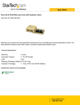
SimpleseD
WiringDiagram
VOLUME
MUTE
CD
HD
TNR1
TNR2
VOLUME
MUTE
CD
HD
TNR1
TNR2
VOLUME
MUTE
CD
HD
TNR1
TNR2
VOLUME
MUTE
CD
HD
TNR1
TNR2
WiringDiagramshownusingUSstandardkeypadsandAllport

5
1
2
SOURCE I NPUT
L
R
L
R
1
2
3
4
L
R
ZONE4
FIXED
VAR
LINEOUT
IROUT
1
3
2
4
SYSTEM
LINK
RS232
STATU S
+12VON=
MUTE
=0V
SPEA KER ANDDATA SIGNAL S
ALL PORTCONNECT ION
Simplese
CON FORMST O
UL ST D.650 0
CER TIFIE DTO
CAN /CSA STD .E60 065
303 3118
C
US
I
N
T
E
R
T
E
K
C
M
NuVo Techn ologi es C incin na tiOhioU SA
D
I
N
T
E
R
T
E
K
FOUR-SOURCEFOUR- ZONE
100~2 40 V50~60 Hz8 5W
USEFORS AT
ORCABL E
NORMA L
USE
56KHz38KHz
1
2
1
2
3
4
5
6
7
8
9
FrontPanelFeatures
1.Stand-byLED
2.ZoneLED
ThisLED(lightemittingdiode)indicates,whenlit,thattheSimpleseamplifierispluggedinto
anACpowersource.
EachoftheseLEDsindicates,whenlit,thatitszonekeypadsareturnedon.
BackPanelFeatures
1.SourceInputs
2.Zone4Lineouts
3.IROUT
4.Mute
5.Status
6.
7.
8.AllportConnection
9.AC
EachofthesestereoRCAinputsreceivesanaudiosignalfromuptofourindependentaudio
sources.
Thesefixedandvariablelineoutsareusedforattachingadditionalamplificationtothezone4
audiooutputs.
TheseoutputsaredesignedtobeusedwiththeincludedIR(Infrared)emitterstotransferIR
functioncommandsfromthezonekeypadstotheappropriateaudiosourceequipment;seeIR
Outputspg.10.
This3.5mmmonoconnectionisdesignedtobeusedinconjunctionwiththeNV-MI1mute
interface;seeMuteInputandtheNV-MI1,pg.15.
This3.5mmmonoconnectionprovidesaconstant+5voltoutputwhenazoneisturnedon.This
canbeusedtotriggerexternalequipment.
This25-pinterminalisusedinconjunctionwiththeAllportcabletointegratethezonekeypads
andspeakersintothesystem;seeAllportTerminationandInstallation,pg.9.
ThisisusedwiththeincludedACpowercabletoprovideelectricalpowertothesystemwhen
attachedtoanactiveACpoweroutlet.
RS232
Link
Thisstereo3.5mminputprovidesbidirectionalserialcommunication.
This3.5mmstereooutputisusedtoexpandtheSimpleseSystemfromfourtoeightzones;see
UsingtheLinkJacktoCreateEightZones,pg.14.

6
1
2
3
4
5
6
NV-A4DKP-DCKeypadFeatures
1.VolumeLevel
2.Volume
3.IRReceiver
4.
5.
6.SourceSelection
Thelevelofthezonevolumeis
indicatedbytheseLEDs(light
emittingdiodes).
Independentaudiovolumelevelfor
eachzoneiscontrolledwiththis
button.
EachkeypadhasanIR(infrared)
receiverlocatedunderthevolume
buttonforwirelesscontrolofthe
audiosourceequipment.
Thesourcebuttonsindependently
selectanyofthefoursources
connectedtotheSimpleseamplifier.
Theselectedsourcebuttonwill
remainlit.
Power
Mute
Thepowerbuttonturnsthatkeypad's
zoneonandoffindependentlyofthe
otherzones.Pressingandholdingthe
powerbuttonturnsallthezonesoff
simultaneously.
Themutebuttontemporarilysilences
anyaudioplayinginthatkeypad's
zone.PressingMuteandtheSource
buttonssimultaneouslyenables
advancedzonecontrol,seepg.11and
12.
VOLUME
MUTE
CD
HD
TNR1
TNR2

7
NV-A4DKP-UKKeypadFeatures
1.VolumeLevel
2.Power
6.Volume
Thelevelofthezonevolumeis
indicatedbytheseLEDs(light
emittingdiodes).
Thepowerbuttonturnsthatkeypad's
zoneonandoffindependentlyofthe
otherzones.Pressingandholdingthe
powerbuttonturnsallthezonesoff
simultaneously.
Independentaudiovolumelevelfor
eachzoneiscontrolledwiththese
buttons.
3.Mute
4.SourceSelection
5.IRReceiver
Themutebuttontemporarilysilences
anyaudioplayinginthatkeypad's
zone.
Thesourcebuttonsindependently
selectanyofthefoursources
connectedtotheSimpleseamplifier.
Theselectedsourcebuttonwillremain
lit.
EachkeypadhasanIR(infrared)
receiverlocatedunderthevolume
buttonforwirelesscontroloftheaudio
sourceequipment.
1
3
4
2
5
6
VOLUME
MUTE
MP3
SAT
HD
CD

1.PWR:
2.Volume:
3.Source/OK:
4.FunctionButtons:
5.Mute:
AllotherbuttonsarenonfunctionalforSimpleseuse.
Thisbuttonturnsthelocalzoneonand
offwithasingletapandperformsan “All
Off” functionwhenthebuttonispushed
andheld.
Thelocalzone’svolumewillincreaseand
decreaseincrementallywiththeVolume
upanddownbuttons.
Thisbuttoncyclesthroughthefour
sourceselectionswitheachtap.
ThesebuttonslabeledF1,F2,F3andF4
providedirectsourceselectionforthe
correspondingsources1-4.
Thismutesthelocalzoneaudiowitha
singletapandun-muteswitha
secondarytap.
1
3
4
2
5
NV-GRC1RemoteControl
8
HOLD
ALL OFF
NV-GRC1
REMOTECONTROL
FAVORITES
VOLUME
1
2
3
4
5
6
7 8 9
11
10
12
SOURCE/OK
PWR
MUTE
SLEEP
DISP
MENU
G2
G1
F1 F2
F3 F4

9
InstallingtheSimpleseSysteminYourHome
I. Prewire
TheSimpleseSystemusesCat-5cableforkeypadcontrolandeithertwo-orfour-conductor16-gaugespeakerwire.Allthewire
is “homerun” fromeachzonetothelocationoftheAllportconnectionhub.
CompleteCat5CrimpingInstructions
TheNuVoaudiosystemsrequireCat5,unshielded,twisted
pair(UTP),forcommunicationbetweenthe
keypads/DisplayPadsandthemainamplifierunit.Each
endofthewireisterminatedwithanRJ45connector.
TheSimpleseSystemcanaccommodate2000totalfeetof
Cat5cable.Forthemostreliableoperation,itisbestthat
nosinglerunofCat5exceeds250feet.
ThecorrectwiringschemefortheCat5cableisstandard
EIA/TIA568A.ProperlyterminatingtheCat5cableis
crucialfortheoperationofthesystem.Itisveryimportant
touseagoodqualitycrimptool,andtestingeachendto
endrunwithaCat5wiretesterwillinsurethatyour
systemoperatesflawlessly,fig.1.
Step-by-StepCrimpingInstructions
1. Stripa2to3inchportionoftheinsulation,
exposingthe4twistedpairs.
2. Untwistthewiresandfanthemout
individually.Arrangethewiresintothe
correctcolorschemeasshowninFig.1.
3. Flattenthewiresintheircorrectorder,and trim
themevenlyacrossthetop.Mostcrimptoolshave
awiretrimmerbuilt-in.Itisbesttotrimthewires
toabout½” inlength.
4. Whileholdingthewiresflatbetweenyourthumb
andforefinger,insertthewiresintotheRJ45
connector,soeachisinitsownslot.Pushthewire
intotheRJ45,soall8conductorstouchtheendof
theconnector.Theinsulationjacketshould
extendbeyondthecrimppointoftheRJ45.
5. InserttheRJ45intothecrimptool receptacleand
squeezethetoolfirmly.Notethataratchettype
toolshouldtightendown untilitnolongerclicks.
6. TheRJ45shouldbefirmlycrimpedtotheCat5
insulation.Itisnecessarythatthe colorscheme
berepeatedidenticallyoneachendofthewire.
Fig.1:EIA568AwiringschemeforCat5Cable
Pin#
1.GreenStripe
2.Green
3.OrangeStripe
4.Blue
5.BlueStripe
6.Orange
7.BrownStripe
8.Brown
Note:Colorslistedas “stripe” areawhitewire
withacoloredstripe.
Step1 Step2 Step3
Step4 Step5 Step6
1 2 3 4 5 6 7 8
Topviewwith
tabdown.
Wiresinsertfrom
thisend.
Pair2
Pair3
Pair4
Pair1
IR Signal-Source 1
Ground
ControlData Bus-
ControlData Bus+
IR Signal-Source 2
Ground
+12V Power
Ground

10
II. SpeakerWireTermination
Itisimportanttokeeptheproperorientationof
positiveandnegativesignalforeachspeaker
connection.Typically,two-conductorspeakerwireuses
redtodenotepositiveandblacktodenotenegative.
Sometypesofwireindicatepositivewithadarkline
runningthroughtheinsulation.Four-conductorwire
canalsobeused.Thishasfourseparatewiresinone
outerjacket,makingitpossibletorunasinglespeaker
wiretoazoneforitspairofspeakers.Thistypeofwire
typicallyusesredandblackforonespeakerandwhite
aspositiveandgreenasnegativeforthesecond
speaker.
Note:TheSimpleseSystemisdesignedtohandleone
pairof8-ohmspeakersperzone.Usingmorethanone
pairofspeakersperzonecouldcausedamagetothe
amplifieroutput.
III. AllportTerminationandInstallation
BoththespeakerwireandCat-5cablesforeachzone
terminateintothebacksideoftheAllport.Theorderof
Cat-5plug-insisirrelevanttotheoperationofthe
system,butitisrecommendedthatyoulabelthe
individualCat-5cablesforfuturereference.Followthe
zoneandpolaritylabelingforthespeakerwire
termination,fig.2.
ThefinalconnectionfromtheAllportismadewiththe
AllportcablesuppliedwiththeSimpleseSystem,fig.3.
NotethattheexamplesshownhereareusingtheUS
standarddecorasizeAllport.
Fig.3
Fig.2
Zon e2
Left Right
-+
Zon e1
Left
Righ t
-+
-+
Zon e3
Left
Righ t
-+
-+
-+
Zon e4
Left Righ t
-+
-+
SYSTEM
LINK
RS232
STATU S
+12VON=
MUTE
=0V
SPEA KE R ANDDATA SIGNALS
ALL PORTCONNECTION
Simplese
CON FORMST O
UL ST D.650 0
CER TIFIE DTO
CAN /CSA STD .E600 65
303 3118
C
US
I
N
T
E
R
T
E
K
C
M
NuVo Techn olo gi esCi nc inn at iOhi oUS A
D
I
N
T
E
R
T
E
K
FOUR-SOURCEFOUR-Z ONE
100~2 40V50~ 60Hz85 W
SYSTEM

11
IV. InstallingtheSimpleseAmplifier
TheSimpleseamplifiercomponentisdesignedtobe
placedonashelforinacomponentrack.Rackear
mountsaresuppliedwiththesystem.Ifyouare
usingtherackearsandmountingtheamplifierwith
othercomponents,youshouldremovethefeet.
Removethetwoscrewsatthefrontofeachsideof
thelidandusethelongerscrewsincludedwiththe
rackearstoattachtheearstotheSimplese
amplifier.
Theaudiosourcesarepluggedintothefoursource
inputsonthebackpaneloftheSimpleseamplifier
usingstereoRCAcables,fig.4.
V. IROutputs
TheSimpleseSystemshipswithfourIRemittersfor
transferringIRdatafromthekeypadreceivers
(locatedunderthevolumebutton)totheIRreceiver
oneachpieceofsourceequipment.Therearetwo
separateIRoutputsectionsonthebackpanel.The
38Khzoutputsareusedformostaudiosources.The
exceptiontothisiscableandsatelliteboxes,which
operateatahigherIRcarrierfrequencycloserto
56Khz.Asecond-sourceoneandtwo56Khzoutput
isavailableforthesedevices.Itisimportantthat
theoutputbeingusedforeachsourcematchesthe
sourceinputnumber.Theoutputsworkindividually
witheachsourcetoallowindependentsource
control.Simplyplugtheemitterintotheappropriate
IRoutputonthebackoftheSimpleseamplifierand
attachtheflasherendovertheIRreceiver
equipment,fig.5.
VI. KeypadandZoneSetup
Eachkeypadrequiresaspecificzonesettingto
establishthekeypad'slocation.Thissettingismade
onthebackofthekeypadusinganeight-position
rotaryswitch.Tosettheswitch,placeasmallslot-
headscrewdriverintheslotintheswitchandturnit
clockwisetotheappropriatezonenumber1-4,fig.
6.Theremainingswitchpositions,5-0,allowforan
additionalkeypadineachzone.Position5
correspondstozone1,6tozone2,7tozone3,and
0tozone4. NotethattheAllportonlyhasfourRJ45
jacks,soadditionalkeypadsrequiretheuseofaCat-
5splitter.
Fig.4
Fig.5
Fig.6
SOURCE IN PU T
L
R
L
R
1
2
3
4
L
R
ZONE4
FIX ED
VAR
LINEOUT
Source1
Tuner1
Audio
Out
SOURCE I NPUT
L
R
L
R
1
2
3
4
L
R
ZONE4
FIXED
VAR
LINEOUT
IROUT
1
3
2
4
USEFORS AT
ORCABL E
NORMA L
USE
56KHz38KHz
1
2
0
1
2
3
4
5
6
7
SimpleseDKeypad
ModelNV-A4DKP
www.nuvotechnologies.com
NuVoTechnologiesLLCCincinnati,OhioUSA
Use onlywith
NuVoSimpleseDSystem
Utiliseruniquementavec
NuVoSimpleseDSystem
WARNING:
AVIS:
Zone
Address
Network
Connection
LocalSource
NV-LSI5
ExampleshownusingtheUSDecorastandardkeypad

12
EQControlandSourceGrouping
Thekeypadscanbeusedtosetspecificzonefunctions.
TheseareforbassandtrebleEQresponseandsource
grouping.Tochangebassresponse,presstheMute
buttonandSource1buttonsimultaneously.Adjustthe
basslevelupordownbyusingtheVolumeUpand
VolumeDownbuttons.ThevolumeindicatorLEDswill
indicatetheoutputlevel,fig.7.Adjusttrebleresponse
usingthesameprocess.Thisisaccessedbypressingthe
MuteandSource2buttons.Oncethedesiredsettingis
made,presstheSourcebuttonagaintoreturnthe
keypadtonormaloperation.
Sourcegroupingisafeaturethatallowsmultiplezones
inanopenlivingspacetoalwayssharethesamesource
selectionbutstillretainindividualvolumeandon/off
control.ThisisachievedbypressingMuteandSource3.
VolumeUpenablesthegroupfunction,andVolume
Downdisablesthegroupfunctionandcausesthe
keypadtooperateindependentlyofallothergroups,
fig.8.
VolumeReset
TheSimpleseSystemkeypadsautomaticallyresetthe
listeningvolumetoalowlevelwhenallzoneshavebeen
turnedoffandazoneisturnedonagain.Ifazoneis
turnedoffandturnedbackonbeforeallthezonesare
turnedoff,itwillreturnatthepreviousvolumelevel.
VOLUME
FLAT
-4dB
+4dB
+6dB
+8dB
-6dB
-8dB
Fig.7
VOLUME
GroupDisabled
GroupEnabled
Fig.8
VOLUME
MUTE
CD
HD
TNR1
TNR2
Pressthe
forbass
control
PressSource2and
Mutebuttonsfor
treblecontrol.
Source1and
Mutebuttons
ThelitvolumeLED
indicatesthetreble
andbasslevels.
ExampleshownusingtheUSDecorastandardkeypad

VOLUME
MUTE
CD
HD
TNR1
TNR2
PresstheMuteand
Source4buttonsto
initiatetheMaster
Mode.
ThelitvolumeLEDwill
flashwhenthekeypad
isinMasterMode.
13
MasterMode/AllOn
TheSimpleseSystemhasanAllOnfeature.Anykeypad
withinthesystem,whichcanbeuptoeightzones,hasthe
abilitytobecomeamastercontrolfortheentirehouse.The
masterkeypadwillcontrolzoneon,volumelevel,andsource
selectionforallotherzones.
ToplaceakeypadinMasterModefunction,simplypressthe
MuteandSource4buttonssimultaneously.Thiswillcause
thevolumeindicatorLEDforthatzone’skeypadtoflash
continuously.Allotherzoneswillthenturnontothesame
relativevolumelevelandincreaseordecreasewiththe
volumeadjustmentonthemasterkeypad.
Anyoftheotherzonekeypadshavetheabilitytooverride
themasterfunctionbyselectinganewsource,changinga
localzone’svolumecontrol,orbyturningalocalzone’s
keypadoffandbackon.
Themastermodeisturnedoffbyrepeatingthesequenceof
pressingtheMuteandSource4buttons.
AllOff
Allthezonesinthesystemcanbeturnedoffsimultaneously
fromanykeypadbypushingandholdingthepowerbutton
untilthekeypadgoescompletelydark.Asinglepushand
releaseofthepowerbuttonwillonlyturnthatzoneoff.If
anotherzoneison,thepowerbuttonwillremainlit.
ExampleshownusingtheUSDecorastandardkeypad

14
VII. UsingtheFixedandVariableLineouts
Zone4isequippedwithtwotypesofpre-amplineoutsforusewithanadditionalamplifier.Thiscanbededicatedtoanoutdoor
zoneorlargelivingareathatwouldbenefitfrommorethanonepairofspeakers.NuVomanufacturesa200-wattstereoamplifier
specificallydesignedforthispurpose,calledtheP2100,althoughanyaudioamplifiercanbeusedwiththelineouts.The
examplesshowninthismanualreferspecificallytotheP2100.
ThevariablelineoutisintendedforuseinazonewhereyouwanttheSimplesekeypadstocontrolthevolumeoutputofthe
externalamplifier,fig.9.
Fig.9
SOURCE INPUT
L
R
L
R
1
2
3
4
L
R
ZONE4
FIXED
VAR
LINEOUT
IROUT
1
3
2
4
SYSTEM
LINK
RS232
STATU S
+5VON=
MUTE
=0V
SPEAKER ANDDATA SIGN ALS
ALL PORTCONNECTION
Simplese
CON FORMST O
UL ST D.6 500
CER TIFIE DTO
CAN /CSA ST D.E 600 65
303 3118
C
US
I
N
T
E
R
T
E
K
C
M
NuVo Techn ol og iesCinci nn at iOhioUSA
D
I
N
T
E
R
T
E
K
FOUR-SOURCEFOUR-ZONE
100~240 V50 ~6 0Hz85W
USEFORSAT
ORCABLE
NORMAL
USE
56KH z38KH z
1
2
R
L
SENSITIVITY
OdBV=1.0RMS
-12
+6
0
LEFT
+6
-12
RIGHT
0
AUDIO
INPUT
2
INPUT
OUTPUT
CONTROL
SPEAKER
MODEL NV-P2100
HIGHEFFICIENCY 200WATT
STEREO AMPLIFIER
NuVo TechnologiesCincinnatiOhio.USA
120V
60HZ
WATTS
250
UNIT
ON
+12VDC
100mA
VOLTAGE
TRIGGER
3-30VOLTS
ACORDC
ON/OFFSWITCH
AUDIO AC/DC
POWER
MODE
OUTPUTPOWER
8OHM:70WX2
4OHM:100WX2
CONTROL
USEONLY WITH250VFUSE
C C C
C
C
C
C
C
C
C
C
C
C
C
C
C
C
C
C
C
C
C
C
C
C
C
C
C
C
C
C
C
C
C
C
C
C
C
C
C
C
C
C
C
C
C
C
C
C
C
C
C
C
C
C
C
C
C
C
C
C
C
C
C
C
C
C
C
C
C
C
C
C
C
C
C
C
C
C
C
C
C
C
C
C
C
C
C
C
C
C
C
C
VOLUME
MUTE
CD
HD
TNR1
TNR2
TheZone4keypadcontrolstheaudiovolume.
DiagramshownusingtheNuVoP2100amplifier
ExampleshownusingtheUSDecorastandardkeypadandAllport

Fig.10
ThefixedlineoutcanbeusedforzoneswhereitismoreappropriatetohaveaseparatevolumecontrolfromtheNuVokeypadfor
theexternalamplifier,fig.10.Agoodexampleofthisusewouldbeanoutdoorzonethatisbeingusedinconjunctionwithzone4.
Allthreeversions,zone4amplifiedoutput,variablelineout,andfixedlineoutcanbeusedsimultaneously.
15
VIII. UsingtheLinkJacktoCreateEightZones
TwoseparateSimpleseSystemscanbemadetoreactasoneusingtheback-panel3.5mmconnectionlabeledLINK.Thisrequires
theuseof “Y” cablestolinkthesourceinputsandIRoutputs.Asinglestereomini-patchcableisthenpluggedintotheLINKjack
onbothSimpleseamplifiers.ThislinkstheAllOffcommandsowhenitisinitiatedatanyofthezonekeypads,alleightzoneswill
turnoff,fig.11.
SOURCE I NPUT
L
R
L
R
1
2
3
4
L
R
ZONE4
FIXED
VAR
LINEO UT
IROUT
1
3
2
4
SYSTEM
LINK
RS232
STATU S
+5VON=
MUTE
=0V
SPEAKE R ANDDATA SIG NA LS
ALL PORTC ONNECTION
Simplese
CON FORMST O
UL ST D.650 0
CER TIFIE DTO
CAN /CSA STD .E600 65
303 3118
C
US
I
N
T
E
R
T
E
K
C
M
NuVo Techn olo gies Ci nci nn atiO hi oUSA
D
I
N
T
E
R
T
E
K
FOUR-SOURCEFOUR-Z ONE
100~2 40V5 0~ 60H z85 W
USEFORS AT
ORCABL E
NORMA L
USE
56KHz38KHz
1
2
R
L
SENSITIVITY
OdBV=1.0RMS
-12
+6
0
LEFT
+6
-12
RIGHT
0
AUDIO
INPUT
2
INPUT
OUTPUT
CONTROL
SPEAKER
MODEL NV-P2100
HIGHEFFICIENCY 200WATT
STEREOAMPLIFIER
NuVoTechnologiesCincinnatiOhio.USA
120V
60HZ
WATTS
250
UNIT
ON
+12VDC
100mA
VOLTAGE
TRIGGER
3-30VOLTS
ACORDC
ON/OFFSWITCH
AUDIO AC/DC
POWER
MODE
OUTPUTPOWER
8OHM:70WX2
4OHM:100WX2
CONTROL
USEONLYWITH250VFUSE
C C C
C
C
C
C
C
C
C
C
C
C
C
C
C
C
C
C
C
C
C
C
C
C
C
C
C
C
C
C
C
C
C
C
C
C
C
C
C
C
C
C
C
C
C
C
C
C
C
C
C
C
C
C
C
C
C
C
C
C
C
C
C
C
C
C
C
VOLUME
MUTE
CD
HD
TNR1
TNR2
Theadditionalspeakersfromzone4arecontrolledby
aseparatevolumecontrol.
DiagramshownusingtheNuVoP2100amplifier
Fig.11
IROUT
IROUT
1
1
3
3
2
2
4
4
SYST EM
SYST EM
LINK
LINK
RS232
RS232
STATU S
+12VON=
STATU S
+12VON=
MUTE
=0V
MUTE
=0V
SPEAKER ANDDATA SIG NA LS
SPEAKER ANDDATA SIG NA LS
ALL PORTC ONNECTI ON
ALL PORTC ONNECTI ON
Simplese
Simplese
USEFORS AT
ORCABL E
USEFORS AT
ORCABL E
NORMA L
USE
NORMA L
USE
56KHz
56KHz
38KHz
38KHz
1
1
2
2
ExampleshownusingtheUSDecorastandardkeypadandAllport

16
IX. MuteInputandtheNuVoMI1
ThebackpaneloftheSimpleseamplifierhasa3.5mmmonoinputlabeledMUTE.ThisisdesignedtobeusedwiththeNuVo
MI1MuteInterface.WhentheMI1isconnected,thesystemwilltemporarilymutewhenthephoneordoorbellrings,fig.12.
Fig.12
MUTEINTERFACE
ADAPTER
NV-MI1
CONNECT TO
MUTEINPUT
A
B
A
B
DOORBELL 1
DOORBELL 2
Connectto TelephoneRJ-11
Line1:Pins3,4Line2:Pins2,5
MuteInterfaceModule
ModelNV-MI1
TheMI1connectstotheNuVoamplifierusingastandard
monopatchcablewithamini-plugoneachend.Plugone
endintotheEXT.MUTEinputonthebackoftheamplifier
andtheotherendintotheinputonthefrontoftheMI1.
ThebackoftheMI1willacceptuptotwoACor
DCvoltagesfromtwodifferentdoorbellchimes.
Thisconnectionisdonewithtwoconductorwire
fromtheterminalsonthedoorbellchimetothe
DoorbellAorDoorbellBinputsonthebackofthe
MI1.Polarityisnotimportantforthisconnection.
Uptotwophonelinescanbebroughtintothe
RJ-11connectiononthebackoftheMI1.The
voltagefromthephoneringerwilltriggerthe
NuVoSystemtomute.
SOURCE I NPUT
L
R
L
R
1
2
3
4
L
R
ZONE4
FIXED
VAR
LINEOUT
IROUT
1
3
2
4
SYSTEM
LINK
RS232
STATU S
+12VON=
MUTE
=0V
SPEA KER ANDDATA SIGNAL S
ALL PORTCONNECT ION
Simplese
CON FORMST O
UL ST D.650 0
CER TIFIE DTO
CAN /CSA STD .E600 65
303 3118
C
US
I
N
T
E
R
T
E
K
C
M
NuVo Techn ologi es C incin na tiOhioU SA
D
I
N
T
E
R
T
E
K
FOUR-SOURCEFOUR- ZONE
100~2 40 V50~60 Hz8 5W
USEFORS AT
ORCABL E
NORMA L
USE
56KHz38KHz
1
2

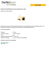
X. TheLSA40LocalSourceAmplifier
TheLSA40ishighlyversatile,40wattstereoamplifierdesignedtobeinstalledinasingleganglowvoltagering.Anaudio
sensingfeatureallowstheLSA40toautomaticallyamplifyanyincomingline-levelaudiosignal.Asdescribedinfig.13,the
LSA40canbeconnectedtotheSimplesekeypadallowingusewithalocalsourceoranincomingNuVosystemsourcethrough
acommonpairofspeakersinanyzone.
R
R
+
+
TheconnectionfromtheLSA40tothe
Simplesekeypadsisdoneusingagreentwo
pinscrewdownterminal.
Atwoconductorwireisusedasavoltagetriggerfrom
theLSA40theNuVozonekeypad.Whenthezoneis
turnedonthisallowstoNuVosystemaudiotopassto
thezonespeakers.Whenthezoneisturnedoffthe
internalamplifieroftheLSA40isautomatically
engaged.
SOURCE INPU T
L
R
L
R
1
2
3
4
L
R
ZON E4
FIX ED
VAR
LINEOUT
IROUT
1
3
2
4
SYSTEM
LIN K
RS2 32
STATUS
+12 VON=
MUT E
=0V
SPEAK ER AN DDATA SIG NAL S
ALL POR TCO NNECT IO N
Simplese
CONF ORMSTO
UL STD .6500
CERT IFIEDT O
CAN/ CSA STD. E6006 5
3033 118
C
US
I
N
T
E
R
T
E
K
C
M
NuVo Tec hnolo giesCi ncinn atiOhi oUSA
D
I
N
T
E
R
T
E
K
FOUR-SOURCEFOUR-ZONE
100 ~240V5 0~60H z85W
USEF ORSAT
ORCA BLE
NOR MAL
USE
56K Hz38K Hz
1
2
Zone2
Left Right
-+
Zon e1
Left
Righ t
-+
-+
Zon e3
Left
Righ t
-+
-+
-+
Zone4
Left Righ t
-+
-+
Theselectedzonespeaker
outputofthe “Generation
D” SimpleseAllport™ is
wireddirectlytotheLSA40.
0
1
2
3
4
5
6
7
VOLUME
MUTE
CD
HD
TNR1
TNR2
INPUT
POWER
LSA40Back
LSA40Front
ACPowerSource
Anystereolinelevel
sourcesignalcanbe
amplifiedthroughthe
localsourcespeakers
usingtheLSA40.
50WattAC
poweradapter
suppliedwith
theLSA40.
NuVoSystemzonespeakers.
AnyNuVoSystemzoneoutputcan
bewiredtotheLSA40LocalSource
Amplifier.
+
+
-
-
L
L
L
L
R
R
+
+
-
-
-
-
MODEL:NV-LSA40
LOCAL SOURCE AMPLIFIER
28VDC
TO
KEYPAD
1.5A
TO AMPLIFIER
TOSPEAKER
WIRESTRIP 5/16” (8MM)
DesignedInUSA
MadeInChina
NuVo TechnologiesLLCCincinnati,OhioUSA
www.nuvotechnologies.com
NV-LSA40
LocalSource Amplifier
Fig.13
17
ExampleshownusingtheUSDecorastandardkeypadandAllport
/