Sanus VXF532 Installation guide
- Category
- Flat panel wall mounts
- Type
- Installation guide

THANK YOU FOR CHOOSING SANUS
THE #1 TV MOUNT BRAND IN THE US.
Scan for easy
install video
VXF532
Instruction Manual

WARNING:This product contains a magnet. If an implanted medical device such as a pacemaker or implantable cardioverter defibrillator (ICD) is in use, magnetic fields may aect the operation of
those devices, resulting in serious injury or death. If you have an implanted medical device, keep at least 13 cm (5in.) between your device and the magnet. Please consult with your physician or medical
professional prior to using this product.
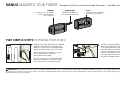
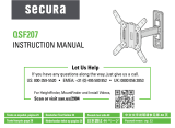
SANUS
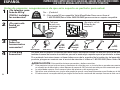
MAGNETIC STUD FINDER
Designed to find your studs and make life easier– included in hardware kit.
TWO SIMPLE STEPS
TO FINDING YOUR STUDS:
Holding it vertically, lightly move the SANUS
Magnetic Stud Finder up and down while
sliding across your wall. The magnet within
will be attracted to the screws in the stud.
Once the magnet has landed on a screw,
place a pencil mark on the wall
directly below the magnet.
You can verify this is a stud by moving the
Magnetic Stud Finder up or down to find
a second or third screw within the wall.
Pull apart the SANUS Magnetic Stud Finder to
expose the probing pin within. Starting about
1
/
2
inch away from the first pencil mark insert
the probing pin into the wall every
1
/
8
inch until
it inserts completely into the wall. Once that
happens, you know you've found one edge of
your stud. Repeat this process till you have
found the stud edges and center of the stud.
Step 1
Step 2
magnet
locates screws in drywall
to show exactly where
your studs are
probing pin
helps find the edges of
your stud within the wall
level
attaches to your wall plate
for hands free leveling

3
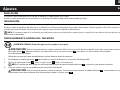
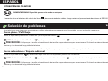
Lo haremos sin estrés
Si tiene preguntas mientras realiza la instalación, llámenos.
1-800-359-5520 (Reino Unido: 0800-056-2853) Estamos listos para ayudarlo.
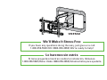
We’ll Make It Stress-Free
If you have any questions along the way, just give us a call.
1-800-359-5520 (UK: 0800-056-2853) We’re ready to help!
VXF532

4
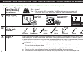
IMPORTANT SAFETY INSTRUCTIONS – SAVE THESE INSTRUCTIONS – PLEASE READ ENTIRE MANUAL PRIOR TO USE
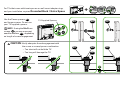
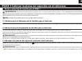
Before getting started, let’s make sure this mount is perfect for you!
No
—
Perfect!
Yes
—
This mount is NOT compatible. Visit MountFinder.Sanus.com or call
1-800-359-5520 (UK: 0800-056-2853) to fi nd a compatible mount.
Please read through these instructions completely to be sure you’re comfortable with this easy install process.
Also check your TV owner’s manual to see if there are any special requirements for mounting your TV.
If you do not understand these instructions or have doubts about the safety of the installation, assembly or use
of this product, contact Customer Service at 1-800-359-5520 (UK: 0800-056-2853).
Do you have
all the tools
needed?
1
2
3
4
What is your
wall made of?
Unsure?
Drywall with
wood studs?
Solid concrete or
concrete block?
150 lb
(68 kg)
CAUTION: Avoid potential personal injuries and property damage!
● This product includes directions and hardware for use with wood stud, solid concrete and concrete block walls –
DO NOT install into drywall alone.
● The wall must be capable of supporting fi ve times the weight of the TV and mount combined.
● Do not use this product for any purpose not explicitly specifi ed by manufacturer.
● Manufacturer is not responsible for damage or injury caused by incorrect assembly or use.
Call Customer Service:
1-800-359-5520 (UK: 0800-056-2853)
Perfect! Perfect!
Ready to
begin?
Does your TV weigh
more than 150 lb
(68 kg) including
accessories?
1/2 in.
(13 mm)
7/32 in.
(5.5 mm)
Wood
Screwdriver Tape Measure Drill Bit Drill Bit Electric Drill Hammer Socket Wrench
3/8 in.
(10 mm)
Concrete

5
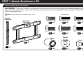
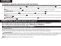
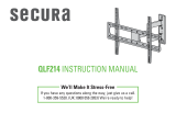
STEP 1 Attach Brackets to TV
Vertical
TV Bracket
01
x2
NOTE: Not all hardware included will be used.
WARNING: This product contains small items that could be a choking hazard if swallowed. Before starting assembly, verify all parts
are included and undamaged. If any parts are missing or damaged, do not return the damaged item to your dealer; contact Customer Service.
Never use damaged parts!
Parts and Hardware for STEP 1
TV Screws
Washer
10
x4
09
x4
11
x2
06
x4
M6x35 mm
M8x35 mmM8x20 mmM8x16 mm
M6x16 mm M6x20 mm
Horizontal
TV Bracket
02
x1
Knob
Spacer
03
x4
05
x4
07
x4
04
x4
08
x4

6
M6
M8
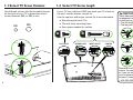
FLAT BACK ROUND BACK CABLESINSET HOLES
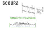
1-1 Select TV
Screw Diameter
1-2 Select TV
Screw Length
Hand thread screws into the threaded inserts
on the back of your TV to determine which
screw diameter (M6, or M8) to use.
Too Short
Too Long
CAUTION:
Verify adequate thread
engagement with the screw or
screw/spacer combination.
- Too short will not hold the TV.
- Too long will damage the TV.
a
b
Correct
If your TV has a flat back AND you want your TV closer to
the wall, use the shorter screws (a).
Use the spacers and longer screws (b) to accommodate:
● Round/irregular back TVs
● TVs with inset mounting holes
● Extra space needed for cables
Standard configurations are
shown. For special applications,
or if you are uncertain about
your hardware selection,
contact Customer Service at
1-800-359-5520
.

7
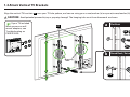
1-3 Attach Vertical TV Brackets
a
Flat Back
b
Round Back / Extra Space
10
09
07
08
10
Align the vertical TV brackets
01
over your TV hole pattern, and secure using your screw/washer (a) or spacer/screw/washer (b) selection.
CAUTION: Avoid potential personal injury or property damage! The hanging tabs must face downward as shown.
Hanging
Tabs
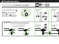
If your TV included
inset spacers or wall
mount adapters, see
Troubleshooting on
PAGES 24-25.
03 04
05
06
01

8
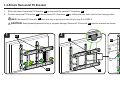
1-4 Attach Horizontal TV Bracket
1. Slide the sides of horizontal TV bracket
02
to align with the vertical TV brackets
01
.
2. Position horizontal TV bracket
02
onto the vertical TV brackets
01
by sliding the four bolts into the four hanging tabs.
NOTE: Horizontal TV bracket
02
does not stay in place until securing in step 3 on PAGE 9.
CAUTION: Avoid potential personal injury or property damage! Horizontal TV bracket
02
must be oriented as shown.
01
02
02
01
02
1 2
01
Hanging
Tab
Bolt

9
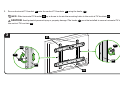
3
3. Secure horizontal TV bracket
02
onto the vertical TV brackets
01
using the knobs
11
.
NOTE: Slide horizontal TV bracket
02
up or down to locate the mounting holes in the vertical TV brackets
01
.
CAUTION: Avoid potential personal injury or property damage! The knobs
11
must be installed to secure horizontal TV bracket
02
onto
the vertical TV brackets
01
.
02
11
02
01
02
01
11

10
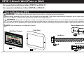
STEP 2 Attach Wall Plate to Wall
Wall Plate Template
Wall Plate
*Sanus Magnetic Stud Finder
Lag Bolts
Concrete Anchors
12
x1
13
x1
14
x1
Parts and Hardware for STEP 2
For wood stud installations, follow STEP 2A on PAGE 11
For concrete installations, follow STEP 2B on PAGE 15
NOTE: Not all hardware included will be used.
WARNING: This product contains small items that could be a choking hazard if swallowed.
Before starting assembly, verify all parts are included and undamaged. If any parts are missing or damaged, do not return the damaged
item to your dealer; contact Customer Service. Never use damaged parts!
*
WARNING: This product contains a magnet. If an implanted medical device such as a pacemaker or implantable cardioverter defi brillator
(ICD) is in use, magnetic fi elds may a ect the operation of those devices, resulting in serious injury or death. If you have an implanted medical device,
keep at least 5 in. (13 cm) between your device and the magnet. Please consult with your physician or medical professional prior to using this product.
15
x4
16
x4
5⁄16 in. x 2 3⁄4 in.

11
1
2
3
14
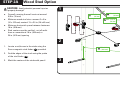
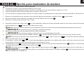
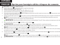
CAUTION: Avoid potential personal injuries
and property damage!
● Drywall covering the wall must not exceed
5/8 in. (16 mm)
● Minimum wood stud size: common 2 x 4 in.
(51 x 102 mm) nominal 1½ x 3½ in. (38 x 89 mm)
● Minimum horizontal space between fasteners:
16 in. (406 mm)
● Stud centers must be verified - not all walls
have a conventional 16 in. (406 mm) or
24 in. (610 mm) spacing
1. Locate a nail/screw in the studs using the
Sanus magnetic stud finder
14
provided.
2. Find the edges of the studs using the probe
of the stud finder
14
.
3. Mark the centers of the studs with pencil.
STEP 2A Wood Stud Option
Min. 16 in.
(406 mm)
Max. 5/8 in.
(16 mm)
Min. 3 1/2 in.
(89 mm)
Min. 1 1/2 in.
(38 mm)

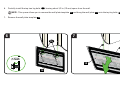
12
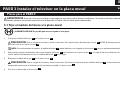
4. Place the wall plate template
12
at your desired height and position the slotted holes over your stud center lines. Level the wall plate
template
12
and tape in place.
NOTE: For assistance in determining wall plate location, see Height Finder at sanus.com.
IMPORTANT: Be sure you mark and drill into the center of the stud.
5. Drill the four pilot holes using a 7/32 in. (5.5 mm) diameter drill bit.
IMPORTANT: Pilot holes must be drilled to a depth of 3 in. (75 mm).
5
12
4
12
3 in. (75 mm)
7/32 in.
(5.5 mm)

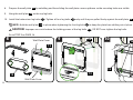
13
6. Partially install the top two lag bolts
15
,
leaving about 1/2 in. (13 mm) space from the wall.
NOTE: This space allows you to remove the wall plate template
12
and hang the wall plate
13
onto the top lag bolts
15
.
7. Remove the wall plate template
12
.
6 7
12
12
15
≈ 1/2 in.
(13 mm)

14
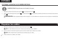
8. Prepare the wall plate
13
by unfolding and then sliding the wall plate covers up/down so the mounting holes are visible.
9. Hang the wall plate
13
on the top lag bolts.
10. Install the bottom two lag bolts
15
. Tighten all four lag bolts
15
only until they are pulled firmly against the wall plate
13
.
NOTE: Hold the wall plate
13
in place when tightening the first lag bolt
15
to keep the plate from shifting out of place.
CAUTION: Improper use could reduce the holding power of the lag bolts
15
. DO NOT over-tighten the lag bolts.
Go to STEP 3 on PAGE 18.
1098
13
13
13
13
Wall Plate Cover
Wall Plate Cover
15
13
15

15
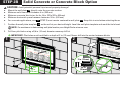
CAUTION: Avoid potential personal injuries and property damage!
● Mount the wall plate
13
directly onto the concrete surface
● Minimum solid concrete thickness: 8 in. (203 mm)
● Minimum concrete block size: 8 x 8 x 16 in. (203 x 203 x 406 mm)
● Minimum horizontal space between fasteners: 24 in. (610 mm)
● For concrete applications, arm
17
(STEP 3) must remain centered in wall plate
13
. Keep this in mind when selecting the wall plate location
1. Position the wall plate template
12
on the wall at your desired height. Level the wall plate template and mark the hole locations.
NOTE: For assistance in determining wall plate location, see Height Finder at sanus.com.
2. Drill four pilot holes using a 3/8 in. (10 mm) diameter masonry drill bit.
IMPORTANT: Pilot holes must be drilled to a depth of 3 in. (75 mm). Never drill into the mortar between blocks.
STEP 2B Solid Concrete or Concrete Block Option
1 2
12
12
Min.
24 in.
(610 mm)
3/8 in.
(10 mm)
3 in. (75 mm)

16
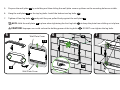
3. Remove the wall plate template
12
and insert four anchors
16
.
CAUTION: Be sure the anchors
16
are seated flush with the concrete surface.
4. Partially install the top two lag bolts
15
, leaving about 1/2 in. (13 mm) space from the wall.
NOTE: This space allows you to hang the wall plate
13
onto the top lag bolts
15
.
3
4
16
15
12
≈ 1/2 in.
(13 mm)

17
5. Prepare the wall plate
13
by unfolding and then sliding the wall plate covers up/down so the mounting holes are visible.
6. Hang the wall plate
13
on the top lag bolts. Install the bottom two lag bolts
15
.
7. Tighten all four lag bolts
15
only until they are pulled firmly against the wall plate
13
.
NOTE: Hold the wall plate
13
in place when tightening the first lag bolt
15
to keep the plate from shifting out of place.
CAUTION: Improper use could reduce the holding power of the lag bolts
15
. DO NOT over-tighten the lag bolts.
765
13
13
13
13
13
Wall Plate Cover
Wall Plate Cover
15
15

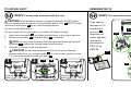
18
1
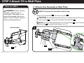
Parts for STEP 3
HEAVY! You may need assistance with this step.
1. Hang the arm assembly
17
onto the wall plate
13
.
CAUTION: Avoid potential personal injury or property damage! For concrete applications,
the arm assembly
17
must remain centered in the wall plate
13
.
NOTE: For wood stud applications, the arm assembly
17
can be slid anywhere along
the wall plate
13
for optimal positioning of your TV.
Arm Assembly
17
WARNING: Before starting
assembly, verify this part is
undamaged. If damaged, do not
return the damaged item to your
dealer; contact Customer Service.
Never use damaged parts!
STEP 3 Attach TV to Wall Plate
3-1 Attach Arm Assembly to Wall Plate
13
17
x1

19
32 4
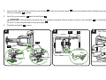
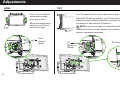
2. Loosen both locking knobs until the arm assembly
17
slips onto the wall plate
13
, then hand tighten both locking knobs evenly to secure
the arm assembly
17
in place.
3. Lock the arm assembly
17
onto the wall plate
13
.
CAUTION: Avoid potential personal injury or property damage! Always make sure your arm assembly
17
is in the locked position
so the TV is securely fastened to the wall plate
13
.
4. Close the wall plate
13
covers.
Wall Plate Cover
Wall Plate Cover
Locking
Knob
17 13
13
13
17
Lock
Locking
Knob

20
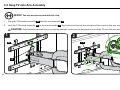
HEAVY! You may need assistance with this step.
1
2
1. Hang the TV/bracket assembly
02
onto the arm assembly
17
.
2. Lock the TV/bracket assembly
02
to the arm assembly
17
by pushing and turning the spring loaded screws on the arm assembly
17
.
CAUTION: Avoid potential personal injury or property damage! Locks must be engaged to secure the TV onto the arm assembly
17
.
3-2 Hang TV onto Arm Assembly
17
02
17
Page is loading ...
Page is loading ...
Page is loading ...
Page is loading ...
Page is loading ...
Page is loading ...
Page is loading ...
Page is loading ...
Page is loading ...
Page is loading ...
Page is loading ...
Page is loading ...
Page is loading ...
Page is loading ...
Page is loading ...
Page is loading ...
Page is loading ...
Page is loading ...
Page is loading ...
Page is loading ...
-
 1
1
-
 2
2
-
 3
3
-
 4
4
-
 5
5
-
 6
6
-
 7
7
-
 8
8
-
 9
9
-
 10
10
-
 11
11
-
 12
12
-
 13
13
-
 14
14
-
 15
15
-
 16
16
-
 17
17
-
 18
18
-
 19
19
-
 20
20
-
 21
21
-
 22
22
-
 23
23
-
 24
24
-
 25
25
-
 26
26
-
 27
27
-
 28
28
-
 29
29
-
 30
30
-
 31
31
-
 32
32
-
 33
33
-
 34
34
-
 35
35
-
 36
36
-
 37
37
-
 38
38
-
 39
39
-
 40
40


Sanus VXF532 Installation guide
- Category
- Flat panel wall mounts
- Type
- Installation guide
Ask a question and I''ll find the answer in the document
Finding information in a document is now easier with AI
in other languages
- español: Sanus VXF532 Guía de instalación
Related papers
Other documents
-
Everbilt DPJC125 User manual
-
Mount-It! MI-1121M-CBL User manual
-
 FORGING MOUNT Long Extension TV Mount Corner Wall Mount TV Bracket Full Motion Installation guide
-
Dynex DX-HTMT0120 Low Profile, Tilt-Mount for TVs 19″-50″ Quick setup guide
-
 Secura QSF207 Installation guide
-
Dynex DX-HTMF1620 Full Motion Mount for TVs 19″-50″ Quick setup guide
-
 Secura QLF214 User manual
-
-
-
 Secura QLF210 Installation guide


