Page is loading ...

SPOOLGUN
INSTRUCTION MANUAL
READ ALL INSTRUCTIONS AND WARNINGS BEFORE USING THIS PRODUCT.
This manual provides important information on proper operation & maintenance.
Every effort has been made to ensure the accuracy of this manual. These
instructions are not meant to cover every possible condition and situation that may
occur. We reserve the right to change this product at any time without
prior notice.
IF THERE IS ANY QUESTION ABOUT A CONDITION BEING SAFE OR UNSAFE,
DO NOT OPERATE THIS PRODUCT!
DO NOT RETURN THIS GENERATOR TO THE RETAILER!
If you experience a problem, have questions or need parts for this product, call
Customer Service at 1-636-532-9888, Monday-Friday, 8 AM - 4 PM Central Time.
A copy of the sales receipt is required.
FOR CONSUMER USE ONLY – NOT FOR PROFESSIONAL USE.
KEEP THIS MANUAL, SALES RECEIPT & APPLICABLE WARRANTY FOR
FUTURE REFERENCE.
CALIFORNIA PROPOSITION 65
WARNING: This product, or the exhaust from this generator, may contain
chemicals, including lead, known to the State of California to cause cancer and
birth defects or other reproductive harm. Wash hands after handling.
Page 1
201707

!
GENERAL SAFETY RULES
WARNING: Read and understand all instructions. Failure to follow all instructions listed below
may result in serious injury or death.
CAUTION: Do not allow persons to operate or assemble this unit until they have read this
manual and have developed a thorough understanding of how this unit works.
WARNING: The warnings, cautions and instructions discussed in this instruction
manual cannot cover all possible conditions or situations that could occur. It must be understood
by the operator that common sense and caution are factorswhich cannot be built into this product, but
must be supplied by the operator.
SAVE THESE INSTRUCTIONS IMPORTANT SAFETY
CONSIDERATIONS
1.1 Your Welding Environment
-Keep the environment you will be welding in free from flammable materials.
-Always keep a fire extinguisher accessible to your welding environment.
-Always have a qualified person install and operate this equipment.
-Make sure the area is clean, dry and ventilated. Do not operate the welder in humid, wet or poorly
ventilated areas.
-Always have your welder maintained by a qualified technician in accordance with local, state and
national codes.
-Always be aware of your work environment. Be sure to keep other people, especially children, away
from you while welding.
-Keep harmful arc rays shielded from the view of
others.
-Mount the welder on a secure bench or cart that will keep the welder secure and prevent it from
tipping over or falling.
1.2 Your Welder’s Condition
-Check ground cable, power cord and welding cable to be sure the insulation is not damaged.
Always replace or repair damaged components before using the welder.
-Check all components to ensure they are clean and in good operating condition before use.
1.3 Use of Your Welder
Do not operate the welder if the output cable, electrode, torch, wire or wire feed system is wet. Do not
immerse them in water. These components and the welder must be completely dry before
attempting to use them.
-Follow the instructions in this manual.
-Keep welder in the off position when not in use.
-Connect ground lead as close to the area being welded as possible to ensure a good ground.
Page 2

!
-Do not allow any body part to come in contact with the welding wire if you are in contact with the
material being welded, ground or electrode from another welder.
-Do not weld if you are in an awkward position. Always have a secure stance while welding to
prevent accidents. Wear a safety harness if working above ground.
-Do not drape cables over or around your body.
-Wear a full coverage helmet with appropriate shade (see ANSI Z87.1 safety standard) and safety
glasses while welding.
-Wear proper gloves and protective clothing to prevent your skin from being exposed to hot metals, UV
and IR rays.
-Do not overuse or overheat your welder. Allow proper cooling time between duty cycles.
-Keep hands and fingers away from moving parts and stay away from the drive rolls.
-Do not point torch at any body part of yourself or anyone else.
-Always use this welder in the rated duty cycle to prevent excessive heat and failure.
1.4 Specific Areas of Danger, Caution or Warning
Electrical Shock
Electric arc welders can produce a shock that can cause injury or death. Touching
electrically live parts can cause fatal shocks and severe burns. While welding, all metal
components connected to the wire are electrically live. Poor ground connections are a hazard, so
secure the ground lead before welding.
-
Wear dry protective apparel: coat, shirt, gloves and insulated footwear.
-Insulate yourself from the work piece. Avoid contacting the work piece or ground.
- Do not attempt to repair or maintain the welder while the power is on.
-Inspect all cables and cords for any exposed wire and replace immediately if found.
-Use only recommended replacement cables and cords.
-Always attach ground clamp to the work piece or work table as close to the weld area as possible.
-Do not touch the torch and the ground or grounded work piece at the same time.
-Do not use a welder to thaw frozen pipes.
Fumes and Gases
-Fumes emitted from the welding process displace clean air and can result in injury or death.
-Do not breathe in fumes emitted by the welding process. Make sure your breathing air is clean and safe.
-Work only in a well-ventilated area or use a ventilation device to remove welding fumes from the
environment where you will be working.
-Do not weld on coated materials (galvanized, cadmium plated or containing zinc, mercury or
barium). They will emit harmful fumes that are dangerous to breathe. If necessary use a ventilator,
respirator with air supply or remove the coating from the material in the weld area.
-The fumes emitted from some metals when heated are extremely toxic. Refer to the material safety data
sheet for the manufacturer’s instructions.
-Do not weld near materials that will emit toxic
fumes when heated. Vapors from cleaners, sprays and
degreasers can be highly toxic when heated.
Page 3

!
UV and IR Arc Rays
The welding arc produces ultraviolet (UV) and infrared (IR) rays that can cause injury to your eyes and
skin. Do not look at the welding arc without proper eye protection.
-Always use a helmet that covers your full face from the neck to top of head and to the back of each ear.
-Use a lens that meets ANSI standards and safety glasses. For welders under 160 amp output, use a
shade 10 lens; for above 160 amp, use a shade 12. Refer to the ANSI standard Z87.1 for more
information.
-Cover all bare skin areas exposed to the arc with protective clothing and shoes. Flame-retardant cloth
or leather shirts, coats, pants or coveralls are available for protection.
-Use screens or other barriers to protect other people from the arc rays emitted from your welding.
-Warn people in your welding area when you are going to strike an arc so they can protect
themselves.
Fire Hazards
Do not weld on containers or pipes that contain or have had flammable, gaseous or liquid combustibles
in them. Welding creates sparks and heat that can ignite flammable and
explosive materials.
-Do not operate any electric arc welders in areas where
flammable or explosive materials are
present.
-Remove all flammable materials within 35 feet of the welding arc. If removal is not possible, tightly cover
them with fireproof covers.
-Take precautions to ensure that flying sparks do not cause fires or explosions in hidden areas, cracks
or areas you cannot see.
-Keep a fire extinguisher close in the case of fire.
-Wear garments that are oil-free with no pockets or cuffs that will collect sparks.
-Do not have on your person any items that are combustible, such as lighters or matches.
-Keep work lead connected as close to the weld area as possible to prevent any unknown,
unintended paths of electrical current from causing electrical shock and fire hazards.
Hot Materials
Welded materials are hot and can cause severe burns if handled improperly.
-Do not touch welded materials with bare hands.
-Do not touch the torch after welding until it has had time to cool down.
!
Page 4

!
Electromagnetic Field
-Electromagnetic fields can interfere with various electrical and electronic devices such as pacemakers.
-Consult your doctor before using any electric arc welder or cutting device.
-Keep people with pacemakers away from your welding area when welding.
-Do not wrap cable around your body while welding.
-Wrap the torch and ground cable together whenever possible.
-Keep the torch and ground cables on the same side of your body.
Shielding Gas Cylinders Can Explode
-High pressure cylinders can explode if damaged, so treat them carefully.
-Never expose cylinders to high heat, sparks, open flames, mechanical shocks or arcs.
-Do not touch cylinder with the torch.
-Do not weld on the cylinder.
-Always secure cylinder upright to a cart or stationary object.
-Keep cylinders away from welding or electrical circuits.
-Use the proper regulators, gas hose and fittings for the specific application.
-Do not look into the valve when opening it.
-Use protective cylinder cap whenever possible.
1.5 Proper Care, Maintenance and Repair
-Always have power disconnected when working on internal components.
- Do not touch or handle PC board without being properly grounded with a wrist strap. Put PC board in
static proof bag to move or ship.
-Do not put hands or fingers near moving parts such as drive rolls of fan.
USE AND CARE
•
Do not modify this unit in any way. Unauthorized modification may impair the function and/or
safety and could affect the life of the equipment. There are specific applications for which this
unit was designed.
•
Always check for damaged or worn out parts before using this unit. Broken parts will affect
the operation. Replace or repair damaged or worn parts immediately.
•
Store idle. When this unit is not in use, store it in a secure place out of the reach of children.
Inspect it for good working condition prior to storage and before re-use.
Page 5

!
TECHNICAL SPECIFICATIONS
Item
Description
Max Amperage
200 amp w/CO2 gas, 160 amp w/Argon Gas
Cooling Method
Air-Cooled
Duty Cycle
35% @ 160 amp
Suggested Wire Size
.030, .035
Wire Spool Diameter
4 inch
Wire Speed
0 to 630 IPM
Torch Cable Length
10 ft.
Weight
6 lbs.
KNOW YOUR SPOOL GUN
Description
The Spool Gun is designed to connect to the HIT140/MMIG140 welders only. It is used to feed wires that
are difficult to feed through the standard MIG torch. Most often this is used for aluminum wires, but any
type of wire can be used on 4 inch spools. With the 4 inch spool mounted right on Spool Gun, the
distance the wire has to travel is greatly reduced, resulting in less feeding problems and better overall
welds. The Spool Gun is rated at a 35% Duty Cycle @ 200 amp when using CO2 gas and is rated at
a 35% Duty Cycle @ 160 amp when using Argon gas. This spool gun is capable of running .030 and
.035 wires and is ideal for light fabrication and welding repair. A rugged storage case is included for
portability and safe storage.
Page!6!

!
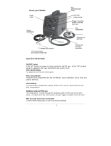
STORAGE CASE
This supplied case gives you an easy way to store and protect your Spool Gun when not in use.
WIRE COMPARTMENT LATCH
Press this latch in to unlock the wire compartment door.
MIG NOZZLE
The MIG nozzle directs the welding shielding gas to the arc.
TORCH Cable
This 10 ft cable contains the weld cable, trigger control cable and shielding gas hose and is
protected with an outer protective cover.
SHIELDING GAS QUICK CONNECT
This quick connect system for shielding gas allows for quick and easy installation on the HIT140 and
MMIG140 welders.
5-PIN TRIGGER CONNECTION
This single snap-on 5 pin trigger connection supplies the spool gun with communication and control
circuits for operation of the spool gun.
WELD POWER CABLE
The weld power cable delivers the welding power from the welder to the arc.
ASSEMBLY
1. ASSEMBLY FOR HIT140 and MMIG140 welders
1.1 The Spool Gun has three connection points at the back of the spool gun. (1) The gas connection is
a slide on quick connector. (2) The weld power connection has a round ring connection. (3) The trigger
connection is the 5-Pin snap on connector.
Page 7

!
1.2 We recommend removing the MIG torch when the Spool Gun is connected to avoid accidental
arcing. Loosen the wing nut retaining bolt and slide the MIG torch out of the front of the machine.
Disconnect the 5-Pin trigger connection on the front of the machine.
1.3 Carefully slide the gas connector and the weld power connection through the weld cable
access opening in the front of the machine.
Weld Cable Access Opening
1.4 Open the wire compartment door
1.5 Connect the gas connection quick connector to the gas connector on the back panel of the wire
compartment.
1.6 Connect the 5-Pin trigger connector to the 5-Pin receptacle on the front of the machine.
1.7 Make certain the SPOOL GUN/MIG TORCH SELECTOR on the front panel is switched into the
SPOOL GUN position.
!
!
Page!8!

!
INSTALLATION
1. DRIVE ROLL INSTALLATION
Before installing any welding wire into the unit, the groove must be placed into position on the wire drive
mechanism. Adjust the drive roller according to the following steps, see following picture about the wire
feeder structure:
!
1.1 Open the spool cover to the spool gun drive compartment.
1.2 Remove the drive roller.
2. INSTALLING WIRE
2.1 MIG wire can be either mild steel, stainless steel or aluminum solid wire. Flux core wire may
also be used for mild steel. For use with 4” spools of wire.
NOTE:
• Metal which is thinner than 22 gauge should not be welded with this spool gun. Attempting to do
so will cause burn through in the metal you are intending to weld.
• Remove any wire that is rusty. If the whole spool is rusty, discard it.
!
!
!
!
!
!
Page!9!
!
!
!
1. Drive Roll
2. Drive Roll Pressure Arm
3. Wire Inlet Guide Tube
4. Pressure Roll
!

!
!
2.2 Install the wire
Electric shock can kill! Always turn the POWER OFF and unplug the power cord from the AC
power source before installing wire.
NOTE:
• Before installing, make sure that you have removed any wire from the spool gun assembly. This will
help to prevent the possibility of the wire jamming inside the spool gun liner.
• Be careful when removing the welding nozzle. The contact tip on this welder is electrically live
when the torch trigger is pulled. Make certain POWER is turned OFF.
2.3 Remove the nozzle and contact tip from the end of the spool gun assembly.
2.4 Remove any wrapping from the outside of the spool of wire. DO NOT UNHOOK THE WIRE AT
THIS TIME.
2.5 Remove the Spool Securement Screw by turning it clockwise.
2.6 Place the spool on the spool hub so that the wire comes off the top of the spool. The welding wire
should always come off the top of the spool into the drive mechanism.
2.7 This spool gun can use 4” spools. The thumb screw on the center post is designed to adjust the
pressure tension on the spool. Turn clockwise to increase spool tension.
Turn the spool while tightening the tension adjustment until the spool slows down and operator feels a
slight drag. The operator may need to repeat
these steps until proper spool tension is achieved.
NOTE: If TOO MUCH tension is applied to the wire spool, the wire will slip on the drive roller or will not
be able to feed at all. If TOO LITTLE tension is applied, the spool of wire will want to unspool itself
when the gun trigger is released. Readjust the spool hub tension as necessary to correct for either
problem.
2.8. After checking to make sure that your welder is disconnected from the AC power source,
remove the leading end of the wire from the spool. DO NOT LET GO OF THE WIRE until told to do
so, or the wire will unspool itself.
Page 10

!
2.9. Using a wire cutter, cut the bent end off the leading end of the wire so that only a straight
leading end remains.
2.10 Squeeze the tension arm toward the front of the gun to open up a gap between the drive roll and
the pressure roll.
2.11. Insert the leading end of the wire into the inlet guide tube. Then push it across the drive roller and
into the liner about 2 inches.
• Make certain that the welding wire is actually going into the torch liner. If not, the wire can jam
or keep the wire from feeding correctly.
2.12 Check to see if the wire is in the drive roller groove, then release the tension arm into place on the
drive roller.
2.13 Tighten (turn clockwise) the pressure arm adjustment knob (if needed) until the tension roller is
applying enough force on the wire to prevent it from slipping out of the drive assembly. DO NOT
OVERTIGHTEN.
2.14. NOW YOU CAN RELEASE THE WIRE.
2.15. . Plug in the welder, turn power switch to the ON position. Set the VOLTAGE and wire speed on
the front of the welder.
NOTE: Due to wire swelling that may occur when aluminum wire gets hot,
it may be necessary to use
a contact tip one size larger than your wire if wire jams occur.
2.16. . Slide the contact tip over the wire (protruding from the end of the torch). Thread the contact tip
into the end of the torch and hand-tighten securely with a pliers.
2.17. Install the nozzle on the gun assembly.
2.18 Cut off the excess wire that extends past the end of the nozzle. Leave ¼” stick out.
Page 11

!
TROUBLESHOOTING
SYMPTOM
POSSIBLE CAUSE
CORRECTIVE ACTION
Wire drive motor does not
turn
Wire feed speed control at zero
Increase wire feed speed control
!
Spool gun/MIG torch selector swith is
not in spool gun position
Change the spool gun/MIG torch selector switch to
spool gun
!
Trigger in not mashed
Wire will feed only when the trigger is mashed
!
Wire drive motor is damaged
Replace wire drive motor
!
Feed roller is not correctly installed
See installation section to correctly install the drive
roller
Wire feeds inconsistently
Torch liner is plugged
Clear or replace torch liner
!
Wire diameter may vary on spool of
wire causing the wire to catch in the
contact tip
Increase the contact tip one size
!
Too much or too little wire tension
See installing the wire section
!
Too much or too little drive roll tension
See setting drive roll tension section
!
Drive roll is worn
Replace drive roll
Can not create an arc
Work piece is painted or rusty
Remove all paint and rust
!
Ground clamp is connected where
there is paint or rust
Remove all paint and rust so ground clamp is
connected to bare metal
!
Ground clamp is not electrically
connected to the work piece
Make certain the ground clamp is connected to the
work piece
!
Trigger is not mashed
This unit is not electrically hot until you mash the torch
trigger
Welding arc is unstable,
excessive spatter
The contact tip is too large
Make certain the correct contact tip is installed
!
Torch liner is plugged
Clear or replace torch liner
!
No shielding gas
Connect shielding gas supply and turn shielding gas on
!
Wire speed setting is incorrect
Refer to the label inside the wire compartment door for
wire speed setting recommendations
!
Voltage setting is incorrect
Refer to the label inside the wire compartment door for
voltage setting recommendations
Page 12

!
DIAGRAM & PARTS LIST
Reference #
Part#
Description
Qty.
1
105200062
NOZZLE
1
2
105200043
CONTACT TIP
1
3
105200088
SPOOL GUN
1
4
105200089
COPPER CONNECTOR
1
!
105200092
DRIVE ROLL
1
!
105200093
DRIVE ROLL PRESSURE ARM
1
!
105200094
INLET GUIDE
1
!
105200095
IDLE ROLL
1
!
105200096
LINER
1
!
105200097
BARREL
1
!
105200098
L SHAPED HEX WRENCH
1
!
105200099
SPOOL SECUREMENT SCREW
1
5
105200090
GAS CONNECTOR
1
6
105200091
5 PIN PLUG
1
!
165200014
OWNER’S MANUAL
1
!
165200015
STORAGE CASE
1
Page 13!
/