Page is loading ...

SB-6-102-L (8/2017) 1 / 4 www.carlisleft.com
HVLP CUP PRESSURE CONTROL ASSEMBLY
AND KK-4980 CUP REGULATOR KIT
SPECIFICATIONS
Regulator: Max. 125 psig inlet
air pressure
0 to 8 psig regulated
air pressure.
Safety Valve: 18 psig blow-off
air pressure
DESCRIPTION
The cup pressure control assembly will allow
the painter to adjust the optimum paint flow
to achieve the best finish by use of an air pres-
sure regulator. The regulator gauge shows
the pressure in the paint cup and allows the
painter to return to that pressure when this
type of paint is used again.
The cup check valve will prevent the cup from
losing pressure. The check valve also prevents
paint from backing up into the air tube if the
cup is tilted. The poppet stem in the cup lid
allows the painter to manually relieve the
cup pressure.
The regulator assembly can be removed
from the gun without the use of tools
before the gun is placed in the gun washer.
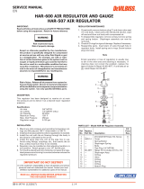
INSTALLATION
Refer to Figure 1. Push in the quick connect
button and connect the fluid control to the gun
handle. Connect the air tube to the paint cup.
For complete assembly, see Page 2.
OPERATION
Risk of bursting. Do not exceed the
maximum pressure noted on the
regulator and paint cup.
If the safety valve does not work
properly, over-pressurization may oc-
cur, causing paint cup rupture or an
explosion. Occasionally pull the ring
on the safety valve to make sure that
the safety valve operates freely. If the
valve is stuck or does not operate
smoothly, it must be replaced with
the same type of valve.
1. Turn the cup regulator knob completely
counter-clockwise until it stops. The air
flow to the paint cup is now shut off.
2. Slowly increase the air pressure to the
spray gun. Do not exceed the recom-
mended inlet pressure for the spray gun
being used.
3. Very slowly turn the cup regulator knob
clockwise while pulling the gun trigger.
Adjust the cup pressure for the proper paint
flow. It is normal for the gauge pressure
reading to be higher when the gun trigger
is released.
4. If you want to decrease the paint flow,
turn the regulator knob counterclockwise.
PUSH DOWN THE CHECK VALVE POPPET
STEM TO RELIEVE THE CUP PRESSURE.
THE REGULATOR GAUGE WILL NOW
SHOW THE ACTUAL CUP PRESSURE. The
cup lid has a check valve that prevents the
cup from losing pressure until the check
valve is opened manually by pushing the
poppet stem down.
Note
For the gauge to read the correct cup
pressure, always approach the desired
pressure from a lower pressure. When
reducing from a higher to a lower set-
ting, first reduce to some pressure less
than desired, then increase to desired
pressure.
Damage to regulator, gauge, and safety
valve will result if paint or solvent is
allowed to flow into these parts. Do not
clean these parts with solvent. Always
remove the regulator assembly (quick
disconnect, regulator, gauge, safety
valve, manifold, and tube) from the
gun before cleaning the gun.
The paint cup is pressurized. Relieve
the cup pressure before opening the
cup. Before removing the cup lid, turn
the cup regulator knob counterclock-
wise to shut off air to the paint cup.
Push down on the check valve poppet
stem to relieve the cup pressure. If this
procedure is not followed, paint may
be forced up the air tube.
MAINTENANCE (Refer to Figure 1)
Regulator Assembly: Before cleaning the gun,
the regulator assembly must be removed or
damage may result from the solvent. Shut off
air to the gun and pull off the air tube at the cup
lid. Push the button on the quick disconnect
and remove regulator assembly from gun.
Quick Disconnect (Regulator): This quick
disconnect does not have an automatic shut
off. ALWAYS SHUT OFF AIR SUPPLY TO GUN
BEFORE PUSHING THE QUICK DISCON-
NECT'S RELEASE BUTTON. To avoid possible
damage to o-ring, do not assemble the quick
connect together under air flow conditions.
Do not allow solvent to contact o-ring, some
solvents may cause the o-ring to swell and
cause difficult reassembly of the quick con-
nect. Replacement o-rings (20-3515-K5) have
been included with this kit.
Check Valve: After each use, clean the check
valve with solvent. It cannot be disassembled.
Do not direct air pressure higher than 15
psi through or at the check valve. This may
damage the valve. The check valve ball and
seat must be free of dried paint for it to seal
properly.
Safety Valve: Prevent solvent and paint from
entering the safety valve. Occasionally pull
ring to make sure it operates freely. If it is
stuck or does not operate smoothly, it must
be replaced with the same type of valve.
Cup Pressure Release (Poppet Stem): When
the poppet stem is pushed down, it is normal
for a small amount of paint mist to discharge
from the poppet stem hole if the check valve
has become wet with paint. To prevent stick-
ing, the poppet stem and hole must be cleaned
with solvent after each use.
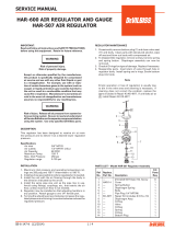
ASSEMBLY
For assembly of KK-4980 and part numbers,
refer to Figures 2 and 3.
EN
SERVICE MANUAL
IMPORTANT! DO NOT DESTROY
It is the Customer's responsibility to have all operators and service personnel read and understand this manual.
Contact your local DeVilbiss representative for additional copies of this manual.
READ ALL INSTRUCTIONS BEFORE OPERATING THIS DEVILBISS PRODUCT.

SB-6-102-L (8/2017)2 / 4
EN
www.carlisleft.com
TGC-429 Check Valve
To prevent any paint
leakage, tighten so
it seals completely
on lid.
TGC-176 Straight Barbed Fitting
Install after TGC-175 air adaptor
body has been positioned.
Apply QH-130 retaining com-
pound to threads before
installing into air adapter
body. Torque snug.
TSC-14 Air Adaptor Stud
Before installing stud, remove
any residue of old thread seal-
ant from hole. Apply QH-130
retaining compound to the two
threads closest to shoulder
before installing into the lid.
Torque snug.
TGC-175 Air Adaptor
Body
Tighten until body con-
tacts lid, then back off to
align fitting with air tube.
FIGURE 1
FIGURE 2
CHECK VALVE AND PRESSURE RELEASE
(ITEMS ABOVE ARE ONLY INCLUDED WITHIN KK-4979)
O-RING ALSO AVAILABLE IN 10 PACK: 23162-024-K10
TGC-173 Poppet
23162-024 O-Ring
Poppet Stem
Check Valve
Regulator
Assembly
Quick
Disconnect
Air Tube
Safety Valve
Flush with
Solvent
Flush with
Solvent
Adaptor
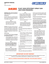
FIGURE 3
30
o
Ref.
90
o
TIA-4326
Safety Valve
SSP-6102-K5
Barbed Fitting
VIEW A-A - POSITION OF FITTINGS
(PARTS INCLUDED WITH JGHV-454 & JGHV-107)
Barbed fitting
to be inline with
corner of hex.
GA-355
Gauge
Hex Socket Pipe Plug
1/8-27 NPT
JGHV-106
Air Tube
JGHV-453
Regulator must be
assembled with arrow
facing away from gun.
*SSP-56
1/4" NPT Coupling Insert
(with O-ring)
DETAIL B
REGULATOR AND COUPLING INSERT
JGHV-108
Adaptor
1/8" NPT
Quick Disconnect
Coupling Body
Align quick connect
release button in this
location to prevent
accidental release.
JGHV-453
Regulator
(See Detail B)
JGHV-107
Manifold
KK-4979
Check Valve/
Poppet
GUN, CUP AND REGULATOR ASSEMBLY
A
A
▲
▲
KK-4978
Adapter/Q.C. Kit
Apply QH-130
retaining compound
to all threads.
*20-3515-5 O-ring Kit
available separately

SB-6-102-L (8/2017) 3 / 4
EN
www.carlisleft.com
NOTES

SB-6-102-L (8/2017)4 / 4
EN
www.carlisleft.com
WARRANTY POLICY
DeVilbiss products are covered by Carlisle Fluid Technologies one year materials and workmanship
limited warranty. The use of any parts or accessories, from a source other than
Carlisle Fluid Technologies, will void all warranties. For specic warranty information please contact
the closest Carlisle Fluid Technologies location listed below.
DeVilbiss is part of Carlisle Fluid Technologies, a global leader in innovative nishing technologies.
For technical assistance or to locate an authorized distributor, contact one of our international sales
and customer support locations.
USA/Canada
Tel: 1-888-992-4657
Fax: 1-888-246-5732
United Kingdom
Tel: +44 (0)1202 571 111
Fax: +44 (0)1202 573 488
China
Tel: +8621-3373 0108
Fax: +8621-3373 0308
Mexico
Tel: +52 55 5321 2300
Fax: +52 55 5310 4790
Japan
Tel: +81 45 785 6421
Fax: +81 45 785 6517
Brazil
Tel: +55 11 5641 2776
Fax: +55 11 5641 1256
Germany
Tel: +49 (0) 6074 403 1
Fax: +49 (0) 6074 403 281
Australia
Tel: +61 (0) 2 8525 7555
Fax: +61 (0) 2 8525 7575
Carlisle Fluid Technologies reserves the right to modify equipment specications without prior notice.
DeVilbiss
®
, Ransburg
®
, ms
®
, BGK
®
, and Binks
®
are registered trademarks of Carlisle Fluid Technologies, Inc.
©2017 Carlisle Fluid Technologies, Inc.
All rights reserved.
For the latest information about our products, visit www.carlisleft.com.
/