Page is loading ...

Owner's Manual
Water Softener
RB-WS-165-132

2
Table of Contents
3
4
5
13
14
WHAT'S INCLUDED
OPERATING CONDITIONS
ASSEMBLY INSTRUCTIONS
STARTUP INSTRUCTIONS
MASTER PROGRAMMING

3
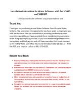
What is included in the box?
For Model RB-WS-165-132 you
will expect the following:
1. Control Valve
2. Resin Tank
3. Parts Bags
4. Owners Manual Zip Bag
5. Brine Tank and brine valve Assembly
What is included with the RB-WS-165-132
Check the entire unit for any shipping related damage, missing parts, or damage to shipping cartons. Contact the transportation company for all
damage and loss claims. Replacement Brand is not responsible for damages in transit.
Small parts, needed to assemble the Softener, are contained in parts bags A and B, the control valve box, or in the instruction(s) zip lock bag. To
avoid loss of the small parts, keep them in the parts bag until you are ready to use them.
1. Control Valve
2. Resin Tank
Distributor
Tube Inside
the Tank
5. Brine Tank Assembly
3. Parts Bags
Upper
Distributor
4
. Owner's Manual Zip bag
1. Manual(s)
2. Hose clamps
3. Lubricant

This softening system will operate at maximum efficiency when the following conditions are considered:
Operating Conditions:
Working Conditions
Working pressure 21psi to 120psi
Water temperature
40 °F - 120 °F (5°C - 50°C)
Working Environment
Environment
temperature
40 °F - 120 °F (5°C - 50°C)
Relative humidity
≤ 95% When temperature is 25°C/77°F
Power source AC100 240V/50 60Hz
Inlet Water Quality
Water turbidity Down-flow Regeneration < 5FTU
Water hardness 1 grain per gallon (gpg) = 17.1 parts per million (ppm)
Chlorine
< 0.1ppm
Iron
2+
< 0.3ppm
All plumbing and electrical work should be performed by an accredited professional to ensure all local, state,
and municipal guidelines are met.
Do not use the control valve with water that is unsafe or of unknown quality.
Do not use the brine tube, injector body, or other connectors on the valve as a handle to carry the system.
Ensure there is salt in the brine tank at all times when this valve is used for softening. The brine tank should contain clean
water softening salt only, at least 99.5% pure. Do not use small grain salt.
When there is moderate to high turbidity, a filter should be installed before the water softening system on the inlet side.
If the water pressure
recommended. If the water pressure is under 21psi, a booster pump must be installed before the water inlet.
Operating Conditions
4

1. Brine Tank – inside the brine tank you will find:
a. Bypass valve
b. Control Valve
c. Clear tubing
d. Lubricant
e. PVC tubing
f. Upper distributor
g. Brine valve
h. Brine well
i. Parts bag A
i. Includes:
1. Brine well overflow elbow
2. Brine well mount
k. Instruction manual(s) zip lock packet
i. Includes
1. 165 Series owner’s manual
2. Hose clamp (2x)
5
ASSEMBLY INSTRUCTIONS
Locate the following parts:

1. Resin Tank - the tank will have a temporary shipping cap, a master O-Ring, and a piece
of tape covering the riser tube. The cap, master O-Ring (another is supplied) and the tape
must be removed and discarded prior to attaching control valve and the upper distributor.
This water softener includes regular control valve connections and a bypass valve connection;
therefore, a set of installation components has been included for each method of installation.
As such, following installation, the installer will be left with an “extra set” of installation
components (animated connectors, brine line flow control, master O-Ring, washers).
2. Read the complete installation guide
3. Unpack the RB-WS-165-132 and ensure all parts pictured and listed above are present. such as
tubing, are necessary Rotate the shutoff valve at the main water line to the OFF position
4. Shut off power supply to water heater – only if you will be draining the tank
5. Open the highest and lowest water faucets in your home (drainage and pressure allowance)
6. Ensure you are aware of local laws and codes regarding the installation, use, and maintenance
of water softeners
7. Begin assembly
Assembling the shipped components:
STEP 1: Attaching the Control Valve to the Resin Tank
A. Lightly coat the master O-ring, from Parts bag B, with silicone grease – insert into bottom of
control valve, as shown below
6
ASSEMBLY INSTRUCTIONS

B. Connect the upper brine filter, or upper distributor, to bottom of control valve, line up slots
and twist, as shown below
C. Center the riser pipe within the resin tank
D. Attach the control valve onto the resin tank, ensuring the upper distributor slides over the riser
pipe
E. Ensure the control valve is properly seated by securely tightening it clockwise into the resin tank
this only requires hand tightening
IF you are installing the supplied bypass valve go to step 3, if you are not installing bypass valve go to
Step 2 – note you will have extra parts based on which method you select
Step 2: Connecting control valve input and output connections with flow meter
A. Insert washers, from parts bag B, into input and output connections on the control valve,
as shown below
B. Locate quick release fittings supplied in control valve box
C. Lightly coat the O-Rings on quick release fittings with lubricant connect them into the bypass
valve connectors. Note: fitting containing on-board water meter probe dock must be
installed on the water outlet connection, as shown below
7
ASSEMBLY INSTRUCTIONS

D. Insert water flow meter probe into on-board water meter probe dock, as shown below
Step 3: Assembly using the included by-pass valve
A. Insert blue washers, from parts bag B, into input and output connections on the control valve,
as shown below
B. Remove the impeller from the outlet animated connector, located inside control valve box, as shown below
C. Insert the impeller into the animated connector, fan blade side facing down, rotating the
impeller to ensure the grooves of the impeller supporter align with the grooves inside the
bypass valve outlet animated connector, as shown below
8
ASSEMBLY INSTRUCTIONS
E. Proceed to step 4

D. Attach the bypass valve onto the control valve, as shown below
.
E. Insert water meter probe from control valve into the by-pass valve’s on-board water meter-
probe holder, ensure it is securely seated, as shown below
Step 4: Connecting the line bine to the brine tank
A. Remove brine well cap from brine well,
as shown below
9
ASSEMBLY INSTRUCTIONS

Figure 1.1
A. Attach brine well bracket (1) to brine tank by sliding brine well bracket over brine well, as shown
in Figure 1.1
B. Secure brine well bracket (2) to top hole of brine tank using threaded attachment, as shown in
Figure 1.1
C. Insert the PVC tube bushing, from parts bag B, into the end of the brine tube completely, as
shown below
ASSEMBLY INSTRUCTIONS
10
D. Feed PVC tubing (3) through the brine well bracket, as show in Figure 1.1
E. Remove connecting nut (4) from brine valve, as shown in Figure 1.1
F. Slide the brine valve nut (4) on over the PVC tubing, push tubing all the way into brine valve,
secure nut, as shown in Figure 1.1

G. Push the brine valve (5) all the way to the bottom of the brine well, ensuring not to loosen or
kink PVC tubing, as shown in Figure 1.1
H. Insert the red brine line flow control from parts bag B with the cone side facing into control
valve, in the control valve brine line connector as shown in the area of magnification below
I. Tighten the nut onto the brine line connection, as shown in the area of magnification below
STEP 5: Connecting overflow line to brine tank
Figure 1.2
ASSEMBLY INSTRUCTIONS
11
A. Connect drain elbow (1), from parts bag A, to bottom hole on brine tank, as shown in Figure 1.2
B. Attach clear drain tubing (2) to the drain elbow, then secure, using a hose clamp, from the
instruction manual(s) zip lock packet, as shown above in Figure 1.2

C. Secure the clear drain tubing over a floor drain or other suitable drain.
Check your local codes to ensure compliance.
STEP 6: Connecting back wash hose to control valve
A. Thread ribbed drain connector, from parts bag b, onto drain connection, as shown below
D. Attach clear drain tube to connector, secure using a hose clamp, from the instruction manual(s)
zip lock packet
B. Secure the clear drain tubing over a floor drain, into a laundry tub, standpipe, or other suitable
drain. Check your local codes to ensure compliance.
C. Leave an air gap of about 1-1/ 2'' between the end of the hose and the drain. This air gap is
necessary to ensure there is no backflow of sewer water into the water softener.
STEP 7: Connect input on control valve to water supply
STEP 8: Connect output on control valve to home plumbing
1
2
ASSEMBLY
INSTRUCTIONS

• System Start-up
Before operating for the first time, flush out the water line and bypass. Be sure the bypass is closed.
•
Turn the water source on at the inlet to the house.
•
Disconnect the bypass from the valve if attached to the valve.
•
Be sure to remove the meter impeller from the bypass before opening the bypass.
•
Put a container under the bypass and open the bypass to allow water to flow through and remove any foreign material out of
the water lines.
•
Close the bypass.
•
Reinstall the meter impeller in the outlet side with the impeller facing in and re-connect the bypass to the valve.
•
Open the bypass.
•
Check for any leaks.
•
Insert meter cable in the outlet side of the bypass or connector, the side the impeller is installed in.
•
Plug in the power cord for the valve.
•
Open a water line and let water flow until water runs clear. Fill brine tank about 1/3 full with water.
•
Press and hold both and buttons simultaneously for 3 seconds to unlock the key pad.
•
Press to advance to 2 - Backwash; this lets air out of the drain line. Process will take 8-10 minutes to purge the system.
Note: when you press the screen will display “-00-” as it positions the ceramic discs. Once “-00-” disappears and the
next phase is displayed, you can press to advance to the next phase.
• Press
to manually advance through the next phase, 3 - Brine & Slow Rinse. Verify the air check valve is closed by*
listening to be sure no air is being drawn into the system.
Press to manually advance to the next phase, 4 - Brine Refill. This phase will fill the brine tank with the correct amount of
water. Allow the brine refill phase to run, do not advance past this phase. Should take about 10 minutes for a 1 cu/ft. system.
After this phase has completed, press to manually advance to 5 - Fast Rinse and again to advance to the Service position.
•
Next add salt to the brine tank. (40lb minimum, 120lb maximum)
Note: We recommend using pellet salt, NOT solar salt.
•
Install brine tank cover.
•
Turn a faucet on, away from the installation location, until the water from the plumbing lines has been purged.
•
Softening system is now fully operational.
•
Take a water sample to verify and test for hardness reduction. We recommend the
10 Panel Tier1 Water Test Kit
. Purchase at:
www.tier1
water.com
STARTUP INSTRUCTIONS
13
If you hear air coming from the drain line:
1. Ensure the brine line nut is secure
2. Ensure the drain line ribbed connector is secure
3. Ensure the brine tank float valve closes when the water is
Brine tank float valve
depleted
*

Programming Key
Time of Day Indicator
∗ LED, displays the time of day.
∗ LED flashes, reset the time of day, see page 17, after electrical service has been interrupted for 3 days or more.
Button Lock Indicator
∗ LED on, indicates the buttons are locked.
and buttons simultaneously for 3 seconds until the LED turns off.
∗ To unlock, press and hold both
Program Mode Indicator
or buttons to view all values. ∗ LED on, enter program display mode. Use
∗ LED Flashes, enter program set mode. Press or buttons to adjust values.
Menu/Confirm Button
∗ Press , the LED turns on; enter program display mode, press
or to view all values.
LED flashes; enter program set mode and press or to adjust the
∗ In program display mode, press the
values.
∗ Press after all program features are set.
Manual /Return Button
∗ Press the
button in any status and the valve will proceed to the next step. (Example: Press the button while the
button while in Backwash status and the
valve is in Service status and it will start a manual regeneration. Press the
valve will go to Brine & Slow Rinse instantly.)
∗ Press the
∗ Press the
∗ Press the
Down and Up Buttons
∗ In program display mode press
∗ In program set mode press
or buttons to view all values.
or buttons to adjust values.
∗ Press and hold both
and
button in program display mode and it will return to In Service. button
in program set mode and it will return to program display mode.
MASTER PROGRAMMING
14
while adjusting the value and it will return to program display mode directly without saving value.
buttons simultaneously for 3 seconds to unlock the programming functions.
*
*
A flashing dynamic display stripe indicates the waster softener is in service
A steady dynamic display stripe indicates the water softener is in the regeneration cycle

Valve Programming Instructions
and
buttons simultaneously for 3 seconds to lift the button lock status.
When LED is on, press and hold both
To program the valve, press and the
LED will turn on. This indicates you are in the programming mode.
or .
To navigate to each programming stage, press
To adjust that programming stage value, press
and use the or
to adjust the values. Follow the process steps
To exit the programming, press and return to service status.
Programming and Sizing Recommendations
∗ Backwash Time - A normal Backwash is between 10-15 minutes. The higher the turbidity a longer backwash time
should be set. However, if the turbidity is more than 5FTU it is best to install a pre-filter.
∗ Brine Refill Time - The Brine Refill speed is related to inlet water pressure and brine line flow control. It is
recommended to lengthen the calculated brine refilling time by 1-2 minutes to make sure there is enough water in tank.
Be sure to install a safety float and shutoff in the brine tank. Refer to page 17.
∗ Fast Rinse Time - Generally Fast Rinse is set for 3-6 times the resin volume; suggest at least 10 minutes.
∗ Regeneration Time - The complete cycle takes about two hours. Set the regeneration time that is convenient for the
end user; usually 2 AM.
∗ Working Process - Service → 2 - Backwash → 3 - Brine & Slow Rinse → 4 - Brine Refill →5 - Fast Rinse.
Note: The display screen will display “-00-“when the drive motor is moving from one stage to the next. Each screen
displays for 15 seconds at the start of each stage.
Valve Display
Backwash Brine & Slow Rinse Brine Refill Fast Rinse
15
MASTER PROGRAMMING
on the following page.

Function
Indicator
Factory Default
Parameter Set Range
Instruction
Time of Day
Random 00:00 23:59 Set the current time of day while the “:” flashes.
Control Mode
A-01 A-01
A-01
Meter Delayed. Regeneration occurs at the set regeneration time
once the gallons used reaches zero (0).
A-02
Meter Immediate. Regeneration occurs immediately once the
gallons used reaches zero (0).
A-03
Not Applicable for
U.S. Customers
Meter Delayed - set resin volume, feed water hardness, and
regeneration factor; the valve will calculate the system capacity.
Regeneration mode same as A-01.
A-04
Not Applicable for
U.S. Customers
Meter Immediate - set resin volume, feed water hardness, and
regeneration factor; the valve will calculate the system capacity.
Regeneration mode same as A-02.
Unit Mode
HU-02 HU-02 01, 02, 03 01-m
3
; 02-gal; 03-L
Regeneration Time
02:00 02:00 00:00 23:59 Regeneration time. “:” light on
Interval Backwash
Times
F-00 00 0 20
Interval backwash times. Number listed after F indicates
number of additional backwashes between services.
Resin Volume
20L 20L 5 500L
Resin volume in pressure tank (L) Only for A-03 and A-04 mode.
Not applicable for U.S. installations.
Feed Water
Hardness
Yd1.2 1.2 0.1 9.9
Feed water hardness (mmo1/L) Only for A-03 and A-04 mode.
Not applicable for U.S. installations.
Exchange Factor
AL.65 0.65 0.30 0.99
Relate to the raw water hardness. When hardness is higher, the
factor is smaller. Only for A-03 and A-04 mode. Not applicable
for U.S. installations.
Water Treatment
Capacity
2500 0-10,000
To figure capacity, take the total resin volume multiplied by .75.
Divide by grains hardness of water supply. Example: 1 Cu/Ft =
32,000 x .75 at 15 grains hardness. (32,000 x .75) ÷ 15= 1600 gal.
Enter that value here.
Backwash Time
10 min. 0 99 59
Backwash time.
Brine & Slow Rinse
Time
60 min. 0 99 59 Brine & Slow Rinse time.
Brine Refill Time 10 min. 0 99 59
Refill time is calculated based on total resin volume. Note: 1 gal
water dissolves 3lbs of salt. Refer to bottom of page 17 for
refill time.
Fast Rinse Time
10 min. 0 99 59
Maximum Interval
Regeneration Days
H-30 30 0 40
Output Control
Mode
b-01 01 01 or 02
MASTER PROGRAMMING
16
Fast Rinse time.
Forced regeneration every 30 days if no water has been used.
Time Clock Valve: to operate as a time clock valve, set the
number of days before desired regenerat
ion.
end of regeneration.
b-
during In Service.
b-01: Signal turns on at start of regeneration and shuts off at
02: Signal available in intervals during regeneration cycles and

Step by Step Programming Instructions
Items Process steps Screen Display
Time of Day
Note: when “12:12” flashes; Time of Day needs to be reset.
1. Press to set Time of Day; both and will light and the “:” symbol will flash.
2. Press , both and “H" value will flash, press or to adjust hour value.
3. Press , both and “H” value will flash, press or to adjust minute value.
4. Press to accept adjustments made. Press to advance to the next programming phase.
Unit Mode
1. Press to enter Unit Mode, and “02” value will flash.
2. Press or buttons to choose HU-1 (m3) , HU-2 (gal) or HU-03 (L).
3. Press to accept adjustments made. Press to advance to the next programming phase.
Regeneration
Time
Note: No regeneration time called for in A-02 Control Mode.
1. Press to enter Regeneration Time, and “Hour” value will flash.
2. Press or to adjust the hour value to the desired regeneration time. (24 hour clock)
3. Press again, and “Minute” value will flash, press or to adjust minute value.
4. Press to accept adjustments made. Press to advance to the next programming phase.
Control
Mode
1. Press to enter Control Mode, and “01”value will flash.
2. Press or to choose A-01 or A-02. A-03 & A-04 Not available in the United States.
3. Press to accept adjustments made. Press to advance to the next programming phase.
Water
Treatment
Capacity
1. Press
to enter Capacity; gal
and along with the “2500” value will flash.
2. Press or to adjust water treatment capacity value (gal or m
3
).
3. Press to accept adjustments made. Press to advance to the next programming phase.
Backwash
Time
1. Press to enter Backwash Time; M, and along with “2-10:00” value will flash.
2. Press or to adjust the backwash time.
3. Press to accept adjustments made. Press to advance to the next programming phase.
Brine & Slow
Rinse Time
1. Press to enter Brine & Slow Rinse Time, and along with “3-60:00” value will flash.
2. Press or to adjust the brine time.
3. Press to accept adjustments made. Press to advance to the next programming phase.
Brine Refill
Time
Note: See instructions below to determine brine refill time needed for your size system.
1. Press to enter Brine Refill Time, and along with “4-10:00” value will flash.
2. Press
or to adjust the brine refill time to 4-03:00.
3. Press to accept adjustments made. Press to advance to the next programming phase.
MASTER PROGRAMMING
17
Calculating Brine Refill Time - The brine refill time is calculated based on total resin volume. For optimal efficiency… 3.0
gallons of water are used for 9x48 (32,000 grain) system
9x48- Brine Refill Time: 3 minutes (3.0 gallons).
Grain Calculation - A family of 3 people with 20 grains of hardness: Your family of 3 will use approx. 225 gallons of water
per day (3 people x 75 gallons per person). Since the water has 20 grains of hardness, you'll need to treat 4,500 grains of
hardness per day (225 X 20). Water treatment capacity = (32,000 x .75) divided by 20 = 1200. Your system will regenerate
after about 5 days (1200/225)
M

Step by Step Programming Instructions Continued
Fast Rinse
Time
1. Press to enter Fast Rinse Time, and along with “5-10:00”value will flash.
2. Press or to adjust the fast rinse time.
3. Press to accept adjustments made. Press to advance to the next programming phase.
Maximum
Regeneration
Days
1. Press to enter Maximum Interval Regeneration Days, and “H-30” value will flash.
2. Press or to adjust the interval regeneration days.
3. Press to accept adjustments made. Press to advance to the next programming phase.
Signal
Output Mode
1. Press to enter Signal Output Mode, and “b-01” value will flash.
2. Press or to adjust the signal output mode value.
3. Press to accept adjustments made. Press and return to service status.
18
MASTER PROGRAMMING
/