Page is loading ...

Installation guide
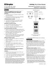
Liquid level sensor - Coaxial D22 version
Type AKS 4100 / AKS 4100U
© Danfoss | DCS (MWA) | 2016.01
DKRCI.PI.SC0.H1.02 | 520H10544 | 1
1
AKS 4100
Factory setting
Refrigerant
Probe
Length
Bottom
Dead
Zone
Bottom
Dead
Zone
[mm] [in.] [mm] [in.]
Ammonia 280 11.0 48 1.9
Improved Bottom dead zone values
after the adjustment of dielectric constant
Refrigerant
Probe
Length
Bottom
Dead
Zone
Bottom
Dead
Zone
[mm] [in.] [mm] [in.]
Ammonia 280 11.0 40 1.6
AKS 4100U
Factory setting
Refrigerant
Probe
Length
Bottom
Dead
Zone
Bottom
Dead
Zone
[in.] [mm] [in.] [mm]
Ammonia 11.0 280 1.9 48
Improved Bottom dead zone values
after the adjustment of dielectric constant
Refrigerant
Probe
Length
Bottom
Dead
Zone
Bottom
Dead
Zone
[in.] [mm] [in.] [mm]
Ammonia 11.0 280 1.6 40
Available lengths:
AKS 4100, 280 mm
AKS 4100U, 11.0 in.
* Values to be entered into HMI Quick Setup menu
and recorded on the setting label.
Stick the setting label onto the Signal Converter
either inside or outside.
Measuring range
4 mA (0 %)*
Top dead zone
60 mm (2.4 in.)
Bottom dead z
one
(see tables)
20 mA
(100 %)*
Probe length*
Reference point
Distance
Surface level
Inner length of the stand pipe
Min: 30 mm (1.2 in.)
2
Danf
oss
M84H0009_1
Danfoss
M84H0010_1
Cover stop
2.5 mm/0.2 in.
Allen Key
Connector
for HMI
Loosen cover stop
Danfoss
M84H0031_1
3
4
5
D22 marking
1a
2a

© Danfoss | DCS (MWA) | 2016.01
DKRCI.PI.SC0.H1.02 | 520H10544 | 2
AKS 4100/4100U connected to EKE 347
AKS 41/41U to AKS 4100/4100U
AKS 41/41U with a.c supply to AKS 4100/4100U with d.c supply
6
7
AKS 4100/4100U
AKS 41
DI1 - main switch
4-20 mA
4-20 mA
24 V DC
yellow
blue
orange
ICAD 1
st
gen
ICAD/ICM
feedback
ICAD 2
nd
gen
blue
24 V AC
L
N
+
–
1
23
yellow
gray
orange
ICAD 1
st
gen (pre 2010)
ICAD 2
nd
gen (2010 +)
yellow
green
brown
brown
white
24 V+
15 V+
5 V+
COM
AI 5
AI 4
AI 3
AI 2
AI 1
COM
COM
DI 2
DI 1
COM
R120
CAN H
CAN L
GND
R GND
D+
D-
COM
AO 1
CAN RJ
24 V DC
24 V DC
1
15 16 17 18 19 20 21 22 23 24
2 3 4 5 6 7 8 9 10 11 12 13 14
Danfoss EKC 347 /
EKE 347 or PLC
24 V a.c (L)
24 V a.c (N)
(+)
AKS 41/41U
(–)
4-20 mA
Danfoss EKC 347 /
EKE 347 or PLC
24 V d.c (+)
24 V d.c (–)
AKS 4100/4100U
–
+

© Danfoss | DCS (MWA) | 2016.01
DKRCI.PI.SC0.H1.02 | 520H10544 | 3
AKS 4100/4100U
connected to PLC
+
–
AKS 4100/4100U
+
–
Active
Analog Input 4-20 mA
14-30 V d.c.
PLC
Enter menu system
Enter QUICK SETUP
Unit change at
distance/level
readout:
m, cm, mm, in, ft
Change between:
Distance*
Level**
Output (%)***
Output (mA)****
4-20 mA output displayed as bar graph
and in percentage [%]
Measurement name (in this example,
DISTANCE)
Device tag name
Measurement reading and unit
Device status (markers)
Marker 1, 2 and 3 (Error)
Hardware problem; the Signal Converter
hardware is defective. Contact Danfoss.
Marker 4 and 5 (Notication)
Depending on the level, the marker is ON or
OFF. Used for Danfoss service information
only.
Keypad buttons
Flashing star indicating unit in operation.
* DISTANCE is a display option.
If the display is set to “DISTANCE” the displayed
value will be the distance from the Reference
point to the top surface of the liquid refrige-
rant (see g. 2).
** LEVEL is display option.
If the display is set to “LEVEL” then the value
displayed will be:
PROBE LENGTH (entered in QUICK SETUP)
– DISTANCE (see g. 2)
*** OUTPUT (%) is display option.
Will represent the level of refrigerant,in
percent, scaled (entered in QUICK SETUP)
according to: SCALE 4 mA (0%), SCALE
20 mA (100%) (see g. 2).
**** OUTPUT I (mA) is display option.
Will represent the level of refrigerant,
in 4-20 milliampere, scaled (entered in
QUICK SETUP) according to: SCALE 4 mA
(4 mA), SCALE 20 mA (20 mA) (see g. 2).
*
AKS 4100
8
9

© Danfoss | DCS (MWA) | 2016.01
DKRCI.PI.SC0.H1.02 | 520H10544 | 4
ENGLISH
Please observe that AKS 4100/4100U
is intended to always be installed in
a standpipe (column/bypass/stilling
well). A standpipe is commonly used
when:
• Servicing the AKS 4100/4100U
• There is highly conductive foam in the tank.
• The liquid is very turbulent or agitated.
AKS 4100/4100U Coaxial with or without
HMI does not need any change of setting
to operate.
Presetting:
4 mA : 230 mm (9.1 in.)
20 mA: 60 mm (2.4 in.)
Refrigerants
AKS 4100/4100U is designed to measure
liquid level in R717(ammonia) applications.
Basic data
AKS 4100/4100U is a passive 2-wire 4-20 mA
sensor that is loop powered.
Supply Voltage
14-30 V d.c. min/max. value for a max. output
of 22 mA at the terminal
Load
RL [Ω] ≤ ((Uext -14 V)/20 mA).
– Default (Error output set to 3.6 mA)
RL [Ω] ≤ ((Uext -14 V)/22 mA).
– (Error output set to 22 mA)
Cable gland
AKS 4100 PG 13, M20×1.5 ;
(cable diameter:
6-8 mm (0.24-0.31in.)
AKS 4100U ½ in. NPT
Terminals (spring loaded)
0.5-1.5 mm
2
(~20-15 AWG)
Enclosure
IP 67 (~NEMA type 4X)
Refrigerant temperature
–60°C/100°C (–76°F/212°F)
Refrigerants
The listed refrigerants are qualied and
approved by Danfoss:
R717 / NH3: –40°C / +50°C (–40°F / +122°F)
Ambient temperature
–40°C / +80°C (–40°F / +175°F)
For HMI : –20°C / +60°C (–4°F / +140°F)
Process pressure
–1 barg / 100 barg (–14.5 psig / 1450 psig)
Mechanical process connection 280 mm
(11 in.). 8 mm (0.3 in.) inner rod.
AKS 4100 G1 inch pipe thread.
Aluminium gasket included
AKS 4100U ¾ in. NPT
(Further details in the data sheet)
Mechanical Installation
Preparations prior to Mechanical Installation
Disassemble the Signal Converter from the
Mechanical process connection (use 5´mm
hex key, see g. 3). Fit the red protection
cover on top of the Mechanical process
connection to protect it againt any moisture
or dirt paticles.
Content supplied (g. 1)
1a: Signal Converter (with or without HMI)
2a: Mechanical process connection
If factory setting needs adjustment
Probe length, scale 4 mA and 20 mA for HMI
Quick Setup.
Probe length: 280 mm (11 in.)
Scale 4 mA: (for max. measuring range)
= Probe Length
– Bottom dead zone (see g. 2)
Scale 20 mA:(for max. measuring range:)
= Top dead zone (see g. 2)
Example (AKS 4100)
Given conditions:
Probe length: 280 mm
Refrigerant: NH
3
, –10°C
The gas constant Er is always adjusted
from the Quick Setup
Probe length:
= 280 mm
SCALE 4 mA setting for max. measuring
range:
= Probe length (280 mm)
– Bottom dead zone (see g. 2)
(40 mm) = 240 mm (9.4 in.)
SCALE 20 mA Setting for Max.
Measuring range:
= Top dead zone (see g. 2)
= 60 mm (2.4 in.)
From page 6:
Dielectric constant of refrigerant gas
parameter 2.5.3 GAS EPS.R
= 1.02
How to mount the AKS 4100/4100U
Converter (see g 3)
1. Using a 5-mm hex key, loosen the setscrew
in the Signal Converter.
2. Slide the Signal Converter down until
it rests on the mechanical process
connection.
3. Turn the Signal Converter to the wanted
position and tighten the set screw with a
5 mm Hexagon key
Electrical installation/connection
Output terminals (g. 4 and 5):
1. Current output –
2. Current output +
3. Grounding terminal
Electrical installation procedure
1. Use a 2.5 mm Allen wrench to loosen the
cover stop.
2. Remove the terminal compartment cover
from the housing.
3. Do not disconnect the wire from the
terminal compartment cover.
Put the terminal compartment cover
adjacent to the housing.
4. Connect the wires to the device.
Tighten the cable entry glands.
5. Attach the terminal compartment cover
to the housing.
6. Use a 2.5 mm Allen wrench to tighten the
cover stop.
Note:
The signal converter can be programmed
with or without mechanical process
connector assembled.
Start up:
• Connect the converter to the power
supply.
• Energize the converter.
Devices with the HMI display option only:
After 10 seconds the screen will display
"Starting up". After 20 seconds the screen will
display the software version numbers. After 30
seconds the default screen (g. 9) will appear.
Precausions when changing from
AKS 41/41U to the AKS 4100/4100U:
Please note:
The AKS 41/41U can be used with a.c. and
d.c. supply, but the AKS 4100/4100U can
only be used with a d.c. supply. Follow the
instructions in g. 6.
Connecting to controller or PLC
Follow the instructions in g. 7 or 8.
Quick Setup →

© Danfoss | DCS (MWA) | 2016.01
DKRCI.PI.SC0.H1.02 | 520H10544 | 5
Quick Setup (all values below are only examples)
• Connect the device to the power supply
(see the section "Electrical installation/
connection").
• Press 3 times.
• Press
• Press
or
to select between SINGLE,
COAXIAL D14 and COAXIAL D22. Choose
COAXIAL D22 and press to conrm.
• Press
(NO) to conrm
AKS 4100
QUICK SETUP ?
YES NO
AKS 4100
PROBE TYPE
SINGLE CABLE
• Press
to change the PROBE LENGTH.
Press
to change the position of the
cursor.
Press
to decrease the value or
to
increase the value.
Press to conrm.
• Press
to change of SCALE 4 mA.
Press
to change the cursor position.
Press
to decrease the value or
to
increase the value.
Press to conrm.
• Press
to change of SCALE 20 mA.
Press
to change the cursor position.
Press
to decrease the value or
to
increase the value.
Press to conrm.
• Wait for QUICK SETUP to complete.
Count down from 8 sec.
• Press to conrm.
• Press
or
to select between
STORE NO or STORE YES.
Press to conrm.
Default screen appears:
Quick Setup completed
AKS 4100
LIQUID CO2 ?
YES NO
AKS 4100
QUICK SETUP
COMPLETED IN 8
AKS 4100
1.0.0
STORE NO
AKS 4100
1.0.0
QUICK START
Note:
The signal converter can be programmed with or without mechanical process connector assembled.
AKS 4100
QUICK SETUP ?
YES NO
When used in NH
3
Default screen
• Press
• Press
• Press
Enter password:
AKS 4100
2.0.0
SUPERVISOR
AKS 4100
2.0.0
__________
AKS 4100
2.1.0
INFORMATION
AKS 4100
2.2.0
TESTS
AKS 4100
2.2.1
SET OUTPUT
AKS 4100
SET OUTPUT
3.5 mA
AKS 4100
SET OUTPUT
8 mA
• Press
• Press
• Press
• Press
to decrease the value or
to
increase the value.
Press to conrm.
• Press 4 times to return to default
screen.
Default screen appears:
Force mA completed and disabled
How to force mA output (all values below are only examples)
AKS 4100
1.0.0
QUICK START
AKS 4100
QUICK SETUP ?
YES NO
AKS 4100
PROBE LENGTH
05000 mm
280 mm
AKS 4100
SCALE 4 mA
04946 mm
230 mm
AKS 4100
SCALE 20 mA
00070 mm
60 mm
AKS 4100
DISTANCE
5000 mm
250mm
AKS 4100
DISTANCE
5000 mm
250 mm
AKS 4100
DISTANCE
5000 mm
250 mm

© Danfoss | DCS (MWA) | 2016.01
DKRCI.PI.SC0.H1.02 | 520H10544 | 6
Default screen
• Press
• Press
• Press
Enter password:
AKS 4100
1.0.0
QUICK START
AKS 4100
2.0.0
SUPERVISOR
AKS 4100
2.0.0
__________
AKS 4100
2.1.0
INFORMATION
AKS 4100
2.5.0
APLICATION
AKS 4100
2.5.1
TRACING VEL.
• Press 4 times.
• Press
• Press 2 times.
• Press to check/change GAS EPS.R.
(Select the correct value from the table
below)
Press to change cursor-
position.
Press
to decrease the value or
to
increase the value.
AKS 4100
2.5.3
GAS EPS. R
AKS 4100
GAS EPS. R
1.066
AKS 4100
2.5.3
GAS EPS. R
AKS 4100
1.0.0
STORE NO
• Press to conrm.
• Press 3 times.
• Press
or
to select between
STORE NO or STORE YES.
Select STORE YES by pressing
Default screen appears:
Entering the dielectric constant of
refrigerant gas completed
How to enter dielectric constant of refrigerant gas (all values below are only examples)
Optional Procedure
If the temperature condition in the stand pipe is known, a constant (dielectric constant of the refrigerant gas) can be entered
(parameter 2.5.3 GAS EPS.R), in order to obtain lower Top and Bottom Dead Zone values (see g. 2).
AKS 4100
QUICK SETUP ?
YES NO
Saturated vapour dielectric constant (default value: 1.066)
Temperature
[°C]
Temperature
[°F]
Dielectric constant
of refrigerant gas
Parameter 2.5.3
GAS EPS.R
–60 → –42 –76 → –43 1.00
–41 → –18 42 → 0 1.01
–17 → –5 1 → 23 1.02
–4 → 4 24 → 39 1.03
5 → 12 40 → 54 1.04
13 → 18 55 → 64 1.05
19 → 24 65 → 75 1.06
25 → 28 76 → 82 1.07
29 → 33 83 → 91 1.08
34 → 37 92 → 99 1.09
38 → 40 100 → 104 1.10
41 → 44 105 → 111 1.11
45 → 47 112 → 117 1.12
48 → 50 118 → 122 1.13
R717 (NH
3
)
Temperature range:
–60°C → +50°C (–76°F → +122°F)
AKS 4100
DISTANCE
5000 mm
250 mm
AKS 4100
DISTANCE
5000 mm
250 mm

© Danfoss | DCS (MWA) | 2016.01
DKRCI.PI.SC0.H1.02 | 520H10544 | 7
Default screen
• Press
• Press
• Press
AKS 4100
1.0.0
QUICK START
AKS 4100
2.0.0
SUPERVISOR
AKS 4100
2.0.0
__________
AKS 4100
2.1.0
INFORMATION
Enter password:
• Press
6 times
• Press
• Press
• Press
or
to see the language
possibilities
Press to conrm.
• Press 3 times
• Press
or
to select between
STORE NO or STORE YES.
Select STORE YES by pressing
Default screen appears:
Language setup completed
How to change the language setting (Default: English)
AKS 4100
QUICK SETUP ?
YES NO
• Go to SUPERVISOR menu (see page 5).
• Go to parameter 2.9.4 Reset Factory.
• Select RESET FACTORY YES
• Press 3 times to return to default screen.
Factory reset completed.
Reset to factory setting
AKS 4100
2.7.0
DISPLAY
AKS 4100
2.7.1
LANGUAGE
AKS 4100
LANGUAGE
ENGLISH
AKS 4100
2.7.1
LANGUAGE
AKS 4100
2.0.0
STORE NO
AKS 4100
DISTANCE
5000 mm
250 mm
AKS 4100
DISTANCE
5000 mm
250 mm

© Danfoss | DCS (MWA) | 2016.01
DKRCI.PI.SC0.H1.02 | 520H10544 | 8
/