Page is loading ...

© Danfoss A/S (AC-MCI/MWA), 10-2013 DKRCI.PI.SC0.E4.02 / 520H5658 1
Danfoss
M84H0023_1
20 mm
(0.8 in.)
Reference point
Reference point
50 mm
(2 in.)
36 mm
(1.4 in.)
Danfoss
M84H0030_1
100 N
(23 lbs)
Danfoss
M84H0021_1
Instruction
Type AKS 4100/4100U
Coaxial D14 version
Danfoss
M84H0021_1
Fig. 1
Fig. 2
Fig. 3
Fig. 4
Danfoss
M84H0024_1
Danfoss
M84H0025_1
Fig. 5
Available lengths:
AKS 4100, 500 mm
AKS 4100, 800 mm
AKS 4100, 1000 mm
AKS 4100, 1200 mm
AKS 4100, 1500 mm
AKS 4100, 1700 mm
AKS 4100, 2200 mm
AKS 4100U, 19.2 in.
AKS 4100U, 30 in.
AKS 4100U, 45 in.
AKS 4100U, 55 in.
AKS 4100U, 65 in.
AKS 4100U, 85 in.
Danfoss
M84H0021_1
Push the wire
through the
center hole.
Kurt
M.
Sand
Digitally signed
by Kurt M. Sand
DN: cn=Kurt M.
Sand, o=Danfoss,
ou=Danfoss,
email=kms@danf
oss.com, c=DK
Date: 2013.10.15
15:35:40 +02'00'

2 DKRCI.PI.SC0.E4.02 / 520H5658 © Danfoss A/S (AC-MCI/MWA), 10-2013
Fig. 8
Fig. 9
Fig. 6
Top
dead
zone
120 mm
(4.7 in.)
Measuring range
Bottom
dead
zone
(see tables)
Min: 30 mm (1.2 in.)
Ø2 mm (0.08 in.)
stainless wire
Probe length*
4 mA (0 %)*
Inner length of the stand pipe
Danfoss
M84H0026_1
20 mA
(100 %)*
Reference point
Distance
Surface level
AKS 4100
Dielectric Constant εr always set during Quick Setup
Refrigerant
Probe
Length
Bottom
Dead
Zone
Bottom
Dead
Zone
[mm] [in.] [mm] [in.]
CO
2
500 19.7
170 6.7
800 31.5
1000 39.4
1200 47.2
1500 59.1
1700 66.9
2200 86.6
Factory setting
Refrigerant
Probe
Length
Bottom
Dead
Zone
Bottom
Dead
Zone
[mm] [in.] [mm] [in.]
Ammonia
500 19.7 95 3.7
800 31.5 104 4.1
1000 39.4 110 4.3
1200 47.2 116 4.6
1500 59.1 125 4.9
1700 66.9 131 5.2
2200 86.6 146 5.8
Improved Bottom dead zone values
after the adjustment of dielectric constant
Refrigerant
Probe
Length
Bottom
Dead
Zone
Bottom
Dead
Zone
[mm] [in.] [mm] [in.]
Ammonia
500 19.7
80 3.2
800 31.5
1000 39.4
1200 47.2
1500 59.1
1700 66.9
2200 86.6
Factory setting
Refrigerant
Probe
Length
Bottom
Dead
Zone
Bottom
Dead
Zone
[mm] [in.] [mm] [in.]
HCFC,HFC
500 19.7 115 4.5
800 31.5 124 4.9
1000 39.4 130 5.1
1200 47.2 136 5.4
1500 59.1 145 5.7
1700 66.9 151 5.9
2200 86.6 166 6.5
Improved Bottom dead zone values
after the adjustment of dielectric constant
Refrigerant
Probe
Length
Bottom
Dead
Zone
Bottom
Dead
Zone
[mm] [in.] [mm] [in.]
HCFC,HFC
500 19.7
100 3.9
800 31.5
1000 39.4
1200 47.2
1500 59.1
1700 66.9
2200 86.6
Danf
oss
M84H0009_1
Danfoss
M84H0010_1
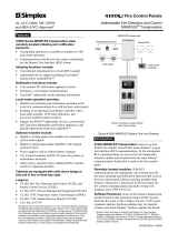
Cover stop
2.5 mm/0.2 in. Allen Key
Connector
for HMI
Loosen cover stop
Danfoss
M84H0031_1
Fig. 7
AKS 4100U
Dielectric Constant εr always set during Quick Setup
Refrigerant
Probe
Length
Bottom
Dead
Zone
Bottom
Dead
Zone
[in.] [in.] [mm]
CO
2
19.2
6.7 170
30
45
55
65
85
Factory setting
Refrigerant
Probe
Length
Bottom
Dead
Zone
Bottom
Dead
Zone
[in.] [in.] [mm]
Ammonia
19.2 3.73 95
30 4.05 103
45 4.50 114
55 4.80 122
65 5.10 130
85 5.70 145
Improved Bottom dead zone values
after the adjustment of dielectric constant
Refrigerant
Probe
Length
Bottom
Dead
Zone
Bottom
Dead
Zone
[in.] [in.] [mm]
Ammonia
19.2
3.1 80
30
45
55
65
85
Factory setting
Refrigerant
Probe
Length
Bottom
Dead
Zone
Bottom
Dead
Zone
[in.] [in.] [mm]
HCFC,HFC
19.2 4.52 115
30 4.84 123
45 5.29 134
55 5.59 142
65 5.89 150
85 6.49 165
Improved Bottom dead zone values after the adjust-
ment of dielectric constant
Refrigerant
Probe
Length
Bottom
Dead
Zone
Bottom
Dead
Zone
[in.] [in.] [mm]
HCFC,HFC
19.2
3.94 100
30
45
55
65
85
* Values to be entered into HMI Quick Setup menu
and recorded on the setting label.
Stick the setting label onto the Signal Converter either
inside or outside.
Please note: It is mandatory to input dielectric constant for CO
2
applications.

© Danfoss A/S (AC-MCI/MWA), 10-2013 DKRCI.PI.SC0.E4.02 / 520H5658 3
Fig. 11
AKS 4100/4100U connected to EKC 347
Fig. 10
AKS 41/41U to AKS 4100/4100U
AKS 41/41U with a.c supply to AKS 4100/4100U with d.c supply
①②③
④①
④
②
③
Danfoss EKC 347
or PLC
24 V a.c (L)
24 V a.c (N)
(+)
AKS 41/41U
(–)
4-20 mA
Danfoss EKC 347
or PLC
24 V d.c (+)
24 V d.c (–)
AKS 4100/4100U
–
+
Danfoss
M84H0027_1
24 V d.c from ICAD
can also be used
Fx/ Eg/ z.B./ par exemple/ p.ej.
EKC 347 5 VA
AKVA coil 20W 55 VA
14-30 V d.c.
+
–
(+)
(–)
Danfoss
M84H0028_1
ICAD 1
st
generation (pre2010)
ICAD 2
nd
generation (2010+)
AKS 4100/4100U

4 DKRCI.PI.SC0.E4.02 / 520H5658 © Danfoss A/S (AC-MCI/MWA), 10-2013
AKS 4100/4100U
connected to PLC
Fig. 12
+
–
AKS 4100/4100U
+
–
Active
Analog Input 4-20 mA
14-30 V d.c.
PLC
Danfoss
M84H0029_1
Enter menu system
Enter QUICK SETUP
Unit change at
distance/level
readout:
m, cm, mm, in, ft
Change between:
Distance*
Level**
Output (%)***
Output (mA)****
4-20 mA output displayed as bar graph
and in percentage [%]
Measurement name (in this example,
DISTANCE)
Device tag name
Measurement reading and unit
Device status (markers)
Marker 1, 2 and 3 (Error)
Hardware problem; the Signal Converter
hardware is defective. Contact Danfoss.
Marker 4 and 5 (Notification)
Depending on the level, the marker is ON or
OFF. Used for Danfoss service information
only.
Keypad buttons
Flashing star indicating unit in operation.
* DISTANCE is a display option.
If the display is set to “DISTANCE” the displayed
value will be the distance from the Reference
point to the top surface of the liquid refrige-
rant (see fig. 6).
** LEVEL is display option.
If the display is set to “LEVEL” then the value
displayed will be:
PROBE LENGTH (entered in QUICK SETUP)
– DISTANCE (see fig. 6)
*** OUTPUT (%) is display option.
Will represent the level of refrigerant,in
percent, scaled (entered in QUICK SETUP)
according to: SCALE 4 mA (0%), SCALE
20 mA (100%) (see fig. 6).
**** OUTPUT I (mA) is display option.
Will represent the level of refrigerant,
in 4-20 milliampere, scaled (entered in
QUICK SETUP) according to: SCALE 4 mA
(4 mA), SCALE 20 mA (20 mA) (see fig. 6).
*
AKS 4100
Fig. 13

© Danfoss A/S (AC-MCI/MWA), 10-2013 DKRCI.PI.SC0.E4.02 / 520H5658 5
English
Please observe that AKS 4100/4100U
is intended to always be* installed
in a standpipe (column/bypass/
stilling well). A standpipe is
commonly used when:
• Servicing the AKS 4100/4100U
• There is highly conductive foam in the tank.
• The liquid is very turbulent or agitated.
Refrigerants
AKS 4100/4100U is designed specifically to
measure liquid level in the most commonly
used refrigerants, including R744 (CO
2
),
R717(ammonia), HCFC, HFC and non corrosive
gases/liquids.
Basic data
AKS 4100/4100U is a passive 2-wire 4-20 mA
sensor that is loop powered.
Supply Voltage
14-30 V d.c. min/max. value for a max. output
of 22 mA at the terminal
Load
RL [Ω] ≤ ((Uext -14 V)/20 mA).
– Default (Error output set to 3.6 mA)
RL [Ω] ≤ ((Uext -14 V)/22 mA).
– (Error output set to 22 mA)
Cable gland
AKS 4100 PG 13, M20×1.5 ;
(cable diameter:
6-8 mm (0.24-0.31in.)
AKS 4100U ½ in. NPT
Terminals (spring loaded)
0.5-1.5 mm
2
(~20-15 AWG)
Enclosure
IP 67 (~NEMA type 4X)
Refrigerant temperature
–60°C/100°C (–76°F/212°F)
Refrigerants
The listed refrigerants are qualified and
approved by Danfoss:
R717 / NH3: –40°C / +50°C (–40°F / +122°F)
R744 / CO2: –50°C / +15°C (–58°F / +59°F)
HCFC:
R22: –50°C / +48°C (–58°F / +118°F)
HFC:
R404A: –50°C/ +15°C (–58°F / +59°F)
R410A: –50°C /+15°C (–58°F / +59°F)
R134A –40°C /+50°C (–40°F /+122°F)
Ambient temperature
–40°C / +80°C (–40°F / +175°F)
For HMI : –20°C / +60°C (–4°F / +140°F)
Process pressure
–1 barg / 100 barg (–14.5 psig / 1450 psig)
Mechanical process connection with 5 m (197
in.) Ø2 mm (0.08 in.) stainless cable:
AKS 4100 G1 inch pipe thread.
Aluminium gasket included
AKS 4100U ¾ in. NPT
(Further details in the Technical Brochure)
Mechanical Installation
Preparations prior to Mechanical Installation
Disassemble the Signal Converter from the
Mechanical process connection (use 5´mm
hex key, see fig. 7). Fit the red protection
cover on top of the Mechanical process
connection to protect it againt any moisture
or dirt paticles.
Content supplied (fig 1)
Signal Converter (with or without HMI)
Mechanical process connection with
5 m (197 in.) Ø2 mm (0.08 in.) stainless
wire
Tube(s)
Bag with:
End Connector (incl. 3 mm set screws.)
3 mm set crews (1 set screw pr. tube)
Red cover to protect Mechanical process
connection , before Signal converter is
mounted
Setting label.
Assembly of the segmented coaxial probe
Please observe that the stainless
steel wire is not permanently creased
or kinked.
1. Take the end of the stainless wire and feed
it through the center hole of the plastic
spacer located at the top of each tube
(see fig. 2). Feed the entire length of the
stainless wire through the tube and out at
the bottom. If more than one tube; repeat
the steps.
2. Assemble the segments of tube and
(see fig. 3). Use a 17 mm open-end
wrench to tighten the assembled parts.
3. If more than one tube; repeat the steps
(see fig. 3).
4. Prior to assemble, disassemble signal
converter and mechanical process
connection, and fit red protection cap at
mechanical process connection. Thread the
fully assembled tube onto the mechanical
process connection .
5. Lock each tube by tightening the set screw
with a 3 mm hex key (see fig. 3).
6. Pull the stainless wire through the end
connector (see fig.4).
7. Attach the end connector to the bottom
of the fully assembled tube.
Tighten the set screw with a 3 mm
hex key (see fig. 4).
8. Pull the end of the stainless steel wire
extending from the end connector with
pliers (see fig. 4) to ensure that the
tension in the signal cable is correct.
Tighten the 2 set screws with a 3 mm
hex key to lock the stainless wire.
9. Cut the stainless wire about 20 mm (0.8 in.)
below the end connector (see fig. 5).
10. Measure the probe length (without the signal
converter) before fitting the assembled probe
in the standpipe (see fig. 6).
Use a torque wrench to tighten the
mechanical process connection
(fig. 1, item 2) to 120 Nm (89 lb/ft).
Probe length, scale 4 mA and 20 mA for
HMI Quick Setup:
Probe length:
See probe length on Danfoss product label or
measure probe length (see fig. 6).
Scale 4 mA: (for max. measuring range)
= Probe Length
– Bottom dead zone (see fig. 6)
Scale 20 mA:(for max. measuring range:)
= Top dead zone (see fig. 6)
Example (AKS 4100)
Given conditions:
Probe length: 1200 mm
Refrigerant: CO
2
, –35°C
The gas constant Er is always adjusted
from the Quick Setup
Probe length:
= 1200 mm
SCALE 4 mA setting for max. measuring range:
= Probe length (1200 mm)
– Bottom dead zone (see fig. 6)
(170 mm) = 1030 mm (40.9 in.)
SCALE 20 mA Setting for Max. Measuring
range:
= Top dead zone (see fig. 6)
= 120 mm (4.7 in.)
From page 8:
Dielectric constant of refrigerant gas
parameter 2.5.3 GAS EPS.R
= 1.02
How to mount the AKS 4100/4100U
Converter (see fig 7)
1. Using a 5-mm hex key, loosen the setscrew
in the Signal Converter.
2. Slide the Signal Converter down until
it rests on the mechanical process
connection.
3. Turn the Signal Converter to the wanted
position and tighten the set screw with a
5 mm Hexagon key
Electrical installation/connection
Output terminals (fig. 8 and 9):
1. Current output –
2. Current output +
3. Grounding terminal
Electrical installation procedure
1. Use a 2.5 mm Allen wrench to loosen the
cover stop.
2. Remove the terminal compartment cover
from the housing.
3. Do not disconnect the wire from the
terminal compartment cover.
Put the terminal compartment cover
adjacent to the housing.
4. Connect the wires to the device.
Tighten the cable entry glands.
5. Attach the terminal compartment cover
to the housing.
6. Use a 2.5 mm Allen wrench to tighten the
cover stop.
Note:
The signal converter can be programmed
with or without mechanical process connector
assembled.
Start up:
• Connect the converter to the power supply.
• Energize the converter.
Devices with the HMI display option only:
After 10 seconds the screen will display
"Starting up". After 20 seconds the screen will
display the software version numbers. After
30 seconds the default screen (fig. 13) will
appear.
Precausions when changing from
AKS 41/41U to the AKS 4100/4100U:
Please note:
The AKS 41/41U can be used with a.c. and
d.c. supply, but the AKS 4100/4100U can
only be used with a d.c. supply. Follow the
instructions in fig. 10.
Connecting to controller or PLC
Follow the instructions in fig. 11 or 12.
Note:
The current output will be set to 3.6 mA
whenever the AKS 4100/4100 detects an
error like Marker 1, 2 or 3 (see page 4).
Quick Setup →

6 DKRCI.PI.SC0.E4.02 / 520H5658 © Danfoss A/S (AC-MCI/MWA), 10-2013
• Connect the device to the power supply
(see the section "Electrical installation/
connection").
• Press 3 times.
• Press
• Press
or
to select between SINGLE,
COAXIAL D14 and COAXIAL D22. Choose
COAXIAL D14 and press to confirm.
• Press (YES) to confirm
• Press to change GAS EPS.R.
(Select the correct value from the tables
on page 8)
Press to change cursor-
position.
Press
to decrease the value or
to
increase the value.
AKS 4100
QUICK SETUP ?
YES NO
AKS 4100
PROBE TYPE
SINGLE CABLE
• Press to confirm.
• Press
to change the PROBE LENGTH.
Press
to change the position of the
cursor.
Press
to decrease the value or
to
increase the value.
Press to confirm.
• Press
to change of SCALE 4 mA.
Press
to change the cursor position.
Press
to decrease the value or
to
increase the value.
Press to confirm.
• Press
to change of SCALE 20 mA.
Press
to change the cursor position.
Press
to decrease the value or
to
increase the value.
Press to confirm.
• Wait for QUICK SETUP to complete.
Count down from 8 sec.
• Press to confirm.
• Press
or
to select between
STORE NO or STORE YES.
Press to confirm.
Default screen appears:
Quick Setup completed
You have the possibility of checking
your settings by pressing
twice.
Press
to return to
default screen.
Quick Setup (all values below are only examples)
• Connect the device to the power supply
(see the section "Electrical installation/
connection").
• Press 3 times.
• Press
• Press
or
to select between SINGLE,
COAXIAL D14 and COAXIAL D22. Choose
COAXIAL D14 and press to confirm.
• Press
(NO) to confirm
AKS 4100
QUICK SETUP ?
YES NO
AKS 4100
PROBE TYPE
SINGLE CABLE
• Press
to change the PROBE LENGTH.
Press
to change the position of the
cursor.
Press
to decrease the value or
to
increase the value.
Press to confirm.
• Press
to change of SCALE 4 mA.
Press
to change the cursor position.
Press
to decrease the value or
to
increase the value.
Press to confirm.
• Press
to change of SCALE 20 mA.
Press
to change the cursor position.
Press
to decrease the value or
to
increase the value.
Press to confirm.
• Wait for QUICK SETUP to complete.
Count down from 8 sec.
• Press to confirm.
• Press
or
to select between
STORE NO or STORE YES.
Press to confirm.
Default screen appears:
Quick Setup completed
AKS 4100
GAS EPS R ?
001.000
AKS 4100
PROBE LENGTH
05000 mm
AKS 4100
SCALE 4 mA
04946 mm
AKS 4100
SCALE 20 mA
00070 mm
AKS 4100
QUICK SETUP
COMPLETED IN 8
AKS 4100
1.0.0
QUICK START
AKS 4100
1.0.0
STORE NO
AKS 4100
DISTANCE
5000 mm
When CO
2
is used:
For all other refrigerants:
AKS 4100
LIQUID CO2 ?
YES NO
AKS 4100
LIQUID CO2 ?
YES NO
AKS 4100
SCALE 4 mA
04946 mm
AKS 4100
SCALE 20 mA
00070 mm
AKS 4100
QUICK SETUP
COMPLETED IN 8
AKS 4100
1.0.0
STORE NO
AKS 4100
DISTANCE
5000 mm
AKS 4100
1.0.0
QUICK START
AKS 4100
PROBE
LENGTH
05000 mm
Note:
The signal converter can be programmed with or without mechanical process connector assembled.
AKS 4100
QUICK SETUP ?
YES NO
AKS 4100
QUICK SETUP ?
YES NO
AKS 4100
COAXIAL 2200 mm
(0 %) 4 mA 1900 mm
(100 %) 20 mA 70 mm
D14

© Danfoss A/S (AC-MCI/MWA), 10-2013 DKRCI.PI.SC0.E4.02 / 520H5658 7
Default screen
• Press
• Press
• Press
Enter password:
AKS 4100
DISTANCE
5000 mm
AKS 4100
1.0.0
QUICK START
AKS 4100
2.0.0
SUPERVISOR
AKS 4100
2.0.0
__________
AKS 4100
2.1.0
INFORMATION
AKS 4100
2.5.0
APLICATION
AKS 4100
2.5.1
TRACING VEL.
• Press 4 times.
• Press
• Press 2 times.
• Press to check/change GAS EPS.R.
(Select the correct value from the tables
below and on page 8)
Press to change cursor-
position.
Press
to decrease the value or
to
increase the value.
AKS 4100
2.5.3
GAS EPS. R
AKS 4100
GAS EPS. R
1.066
AKS 4100
2.5.3
GAS EPS. R
AKS 4100
1.0.0
STORE NO
AKS 4100
DISTANCE
5000 mm
• Press to confirm.
• Press 3 times.
• Press
or
to select between
STORE NO or STORE YES.
Select STORE YES by pressing
Default screen appears:
Entering the dielectric constant of
refrigerant gas completed
How to enter dielectric constant of refrigerant gas (all values below are only examples)
Optional Procedure
If the temperature condition in the stand pipe is known, a constant (dielectric constant of the refrigerant gas) can be entered
(parameter 2.5.3 GAS EPS.R), in order to obtain lower Top and Bottom Dead Zone values (see fig. 6).
Default screen
• Press
• Press
• Press
Enter password:
AKS 4100
DISTANCE
5000 mm
AKS 4100
2.0.0
SUPERVISOR
AKS 4100
2.0.0
__________
AKS 4100
2.1.0
INFORMATION
AKS 4100
2.2.0
TESTS
AKS 4100
2.2.1
SET OUTPUT
AKS 4100
SET OUTPUT
3.5 mA
AKS 4100
SET OUTPUT
8 mA
AKS 4100
DISTANCE
5000 mm
• Press
• Press
• Press
• Press
to decrease the value or
to
increase the value.
Press to confirm.
• Press 4 times to return to default
screen.
Default screen appears:
Force mA completed and disabled
How to force mA output (all values below are only examples)
AKS 4100
1.0.0
QUICK START
AKS 4100
QUICK SETUP ?
YES NO
AKS 4100
QUICK SETUP ?
YES NO

8 DKRCI.PI.SC0.E4.02 / 520H5658 © Danfoss A/S (AC-MCI/MWA), 10-2013
Saturated vapour dielectric constant (default value: 1.066)
Temperature
[°C]
Temperature
[°F]
Dielectric constant
of refrigerant gas
Parameter 2.5.3
GAS EPS.R
–60 → –42 –76 → –43 1.00
–41 → –18 42 → 0 1.01
–17 → –5 1 → 23 1.02
–4 → 4 24 → 39 1.03
5 → 12 40 → 54 1.04
13 → 18 55 → 64 1.05
19 → 24 65 → 75 1.06
25 → 28 76 → 82 1.07
29 → 33 83 → 91 1.08
34 → 37 92 → 99 1.09
38 → 40 100 → 104 1.10
41 → 44 105 → 111 1.11
45 → 47 112 → 117 1.12
48 → 50 118 → 122 1.13
R717 (NH
3
)
Temperature range:
–60°C → +50°C (–76°F → +122°F)
Temperature
[°C]
Temperature
[°F]
Dielectric constant
of refrigerant gas
Parameter 2.5.3
GAS EPS.R
–56.0 → –42.0 –69 → –43 1.01
–41.0 → –28.0 –42 → –18 1.02
–27.0 → –17.0 –17 → 2 1.03
–16.0 → –9.0 3 → 16 1.04
–8.0 → –3.0 17 → 27 1.05
–2.0 → 2 28 → 36 1.06
3 → 7 37 → 45 1.07
8 → 11 46 → 52 1.08
12 → 14 53 → 58 1.09
15 59 1.10
R744 (CO
2
)
Temperature range:
–56°C → +15°C (–69°F → +59°F)
Temperature
[°C]
Temperature
[°F]
Dielectric constant
of refrigerant gas
Parameter 2.5.3
GAS EPS.R
–60 → –50 –76 → –58 1.00
–49 → –25 57 → –13 1.01
–24 → –10 –12 → 14 1.02
–9 → 0 15 → 32 1.03
1 → 8 33 → 46 1.04
9 → 15 47 → 59 1.05
16 → 21 60 → 70 1.06
22 → 26 71 → 79 1.07
27 → 31 80 → 88 1.08
32 → 35 89 → 95 1.09
36 → 39 96 → 102 1.10
40 → 42 103 → 108 1.11
43 → 45 109 → 113 1.12
46 → 48 114 → 118 1.13
R22
Temperature range:
–60°C → +48°C (–76°F → +118°F)
Temperature
[°C]
Temperature
[°F]
Dielectric constant
of refrigerant gas
Parameter 2.5.3
GAS EPS.R
–60 → –42 –76 → –43 1.00
–41 → –18 –42 → –0 1.01
–17 → –4 1 → 25 1.02
–3 → 5 26 → 41 1.03
6 → 13 42 → 56 1.04
14 → 20 57 → 68 1.05
21 → 25 69 → 77 1.06
26 → 30 78 → 86 1.07
31 → 34 87 → 94 1.08
35 → 38 95 → 100 1.09
39 → 42 101 → 108 1.10
43 → 45 109 → 113 1.11
46 → 48 114 → 119 1.12
49 → 50 120 → 122 1.13
R134a
Temperature range:
–60°C → +50°C (–76°F → +122°F)
Temperature
[°C]
Temperature
[°F]
Dielectric constant
of refrigerant gas
Parameter 2.5.3
GAS EPS.R
–60 → –47 –76 → –52 1.01
–46 → –35 –51 → –31 1.02
–34 → –26 –30 → –14 1.03
–25 → –19 –13 → –2 1.04
–18 → –14 –1 → 7 1.05
–13 → –9 8 → 16 1.06
–8 → –4 17 → 25 1.07
–3 → 0 26 → 32 1.08
1 → 3 33 → 38 1.09
4 → 6 39 → 43 1.10
7 → 9 44 → 49 1.11
10 → 12 50 → 54 1.12
13 → 15 55 → 59 1.13
R404A
Temperature range:
–60°C → +15°C (–76°F → +59°F)
Temperature
[°C]
Temperature
[°F]
Dielectric constant
of refrigerant gas
Parameter 2.5.3
GAS EPS.R
–65 → –47 –85 → –52 1.01
–46 → –35 –51 → –31 1.02
–34 → –26 –30 → –14 1.03
–25 → –19 –13 → –2 1.04
–18 → –13 –1 → 9 1.05
–12 → –8 10 → 18 1.06
–7 → –4 19 → 25 1.07
–3 → 0 26 → 32 1.08
1 → 4 33 → 40 1.09
5 → 7 41 → 45 1.10
8 → 10 46 → 50 1.11
11 → 12 51 → 54 1.12
13 → 15 55 → 59 1.13
R410A
Temperature range:
–65°C → +15°C (–85°F → +59°F)
Temperature
[°C]
Temperature
[°F]
Dielectric constant
of refrigerant gas
Parameter 2.5.3
GAS EPS.R
–60 → –48 –76 → –54 1.01
–47 → –36 –53 → –32 1.02
–35 → –28 –31 → –18 1.03
–27 → –21 –17 → –6 1.04
–20 → –15 –17 → –5 1.05
–14 → –10 –4 → 14 1.06
–9 → –6 13 → 22 1.07
–5 → –2 23 → 29 1.08
–1 → 2 30 → 36 1.09
3 → 5 37 → 41 1.10
6 → 8 42 → 47 1.11
9 → 11 48 → 52 1.12
12 → 13 53 → 56 1.13
14 → 15 57 → 59 1.14
R507
Temperature range:
–60°C → +15°C (–76°F → +59°F)

© Danfoss A/S (AC-MCI/MWA), 10-2013 DKRCI.PI.SC0.E4.02 / 520H5658 9
Default screen
• Press
• Press
• Press
AKS 4100
DISTANCE
5000 mm
AKS 4100
1.0.0
QUICK START
AKS 4100
2.0.0
SUPERVISOR
AKS 4100
2.0.0
__________
AKS 4100
2.1.0
INFORMATION
AKS 4100
DISTANCE
5000 mm
Enter password:
• Press
6 times
• Press
• Press
• Press
or
to see the language
possibilities
Press to confirm.
• Press 3 times
• Press
or
to select between
STORE NO or STORE YES.
Select STORE YES by pressing
Default screen appears:
Language setup completed
How to change the language setting (Default: English)
AKS 4100
QUICK SETUP ?
YES NO
• Go to SUPERVISOR menu (see page 7).
• Go to parameter 2.9.4 Reset Factory.
• Select RESET FACTORY YES
• Press 3 times to return to default screen.
Factory reset completed.
Reset to factory setting
AKS 4100
2.7.0
DISPLAY
AKS 4100
2.7.1
LANGUAGE
AKS 4100
LANGUAGE
ENGLISH
AKS 4100
2.7.1
LANGUAGE
AKS 4100
2.0.0
STORE NO

10 DKRCI.PI.SC0.E4.02 / 520H5658 © Danfoss A/S (AC-MCI/MWA), 10-2013

© Danfoss A/S (AC-MCI/MWA), 10-2013 DKRCI.PI.SC0.E4.02 / 520H5658 11

12 DKRCI.PI.SC0.E4.02 / 520H5658 © Danfoss A/S (AC-MCI/MWA), 10-2013
www.danfoss.com/ir
/