Page is loading ...

Contents
1 How to Read this Design Guide
3
2 Safety and Conformity
4
2.1.2 Abbreviations 4
2.1.3 CE Conformity and Labelling 4
2.1.4 EMC-Directive 2004/108/EG 5
2.1.5 Warnings 5
3 Introduction to Harmonics and Mitigation
7
3.1 What are Harmonics?
7
3.1.1 Linear Loads 7
3.1.2 Non-linear Loads 8
3.1.3 The Effect of Harmonics in a Power Distribution System 9
3.2 Harmonic Limitation Standards and Requirements
9
3.3 Harmonic Mitigation
11
4 Introduction to Advanced Harmonic Filters
12
4.1 Operation Principle
12
4.1.1 Power Factor 13
4.1.2 Capacitor Disconnect 14
5 Selection of Advanced Harmonic Filter
15
5.1 How to Select the Correct AHF
15
5.1.1 Calculation of the Correct Filter Size Needed 15
5.1.2 Calculation Example 15
5.1.3 Voltage Boost 15
5.2 Electrical Data
16
5.2.1 Accessories 26
5.3 General Specification
27
5.3.1 General Technical Data 27
5.3.2 Environmental Data 27
6 How to Install
29
6.1 Mechanical Mounting
29
6.1.1 Safety Requirements of Mechanical Installation 29
6.1.2 Mounting 29
6.1.3 Recommendations for Installation in Industrial Enclosures 29
6.1.4 Ventilation 29
6.2 Electrical Installation
32
6.2.1 Over Temperature Protection 32
6.2.2 Capacitor Disconnect 33
Contents AHF005/010 Design Guide
MG.80.C4.02 - VLT
®
is a registered Danfoss trademark
1

6.2.3 Wiring 34
6.2.4 Fuses 36
6.3 Mechanical Dimensions
37
6.3.1 Sketches 37
6.3.2 IP00 Enclosures 47
6.3.3 Physical Dimensions 54
6.3.4 IP00 Dimensions 54
6.3.5 Weight 55
7 How to Programme the Frequency Converter
56
7.1.1 DC-link Compensation Disabling 56
Index
57
Contents AHF005/010 Design Guide
2 MG.80.C4.02 - VLT
®
is a registered Danfoss trademark

1 How to Read this Design Guide
This Design Guide will introduce all aspects of the Advanced
Harmonic
Filters for your VLT
®
FC Series Drive. It describes
Harmonics and how to mitigate them, provide installation
instructions and guidance about how to programme the
frequency converter.
Danfoss technical literature is also available online at
www.danfoss.com/BusinessAreas/DrivesSolutions/Documen-
tations/Technical+Documentation.
How to Read this Design Gui... AHF005/010 Design Guide
MG.80.C4.02 - VLT
®
is a registered Danfoss trademark
3
1 1

2 Safety and Conformity
2.1.1 Symbols
Symbols used in this manual
NOTE
Indicates
something to be noted by the reader.
CAUTION
Indicates a general warning.
WARNING
Indicates a high-voltage warning.
✮
Indicates default setting
2.1.2 Abbreviations
Active Power P
Advanced Harmonic Filter AHF
Alternating current AC
American wire gauge AWG
Ampere/AMP A
Apparent Power S
Degrees Celsius
°C
Direct current DC
Displacement Power Factor DPF
Electro Magnetic Compatibility EMC
Drive FC
Gram g
Harmonic Calculation Software HCS
Hertz Hz
Kilohertz kHz
Local Control Panel LCP
Meter m
Millihenry Inductance mH
Milliampere mA
Millisecond ms
Minute min
Motion Control Tool MCT
Nanofarad nF
Newton Meters Nm
Nominal motor current I
M,N
Nominal motor frequency f
M,N
Nominal motor power P
M,N
Nominal motor voltage U
M,N
Parameter par.
Partial Weighted Harmonic
Distortion
PWHD
Point of Common Coupling PCC
Power Factor PF
Protective Extra Low Voltage PELV
Rated Inverter Output Current I
INV
Reactive Power Q
Revolutions Per Minute RPM
Second sec.
Short circuit ratio R
SCE
Total Demand Distortion TDD
Total Harmonic Distortion THD
Total Harmonic Current Distortior THiD
Total Harmonic Voltage Distortior THvD
True Power Factor TPF
Volts V
I
VLT,MAX
The maximum output current.
I
VLT,N
The rated output current
supplied
by the frequency
converter.
Equipment containing electrical components
may
not be disposed of together with domestic
waste.
It must be separately collected with electrical
and electronic waste according to local and
currently valid legislation.
AHF005/010
Design Guide
2.1.3 CE Conformity and Labelling
What is CE Conformity and Labelling?
The
purpose of CE labelling is to avoid technical trade
obstacles within EFTA and the EU. The EU has introduced the
CE label as a simple way of showing whether a product
complies with the relevant EU directives. The CE label says
nothing about the specifications or quality of the product.
The low-voltage directive (73/23/EEC)
Frequency converters must be CE labelled in accordance
with the low-voltage directive of January 1, 1997. The
directive applies to all electrical equipment and appliances
used in the 50 - 1000V AC and the 75 - 1500V DC voltage
ranges. Danfoss CE-labels in accordance with the directive
and issues a declaration of conformity upon request.
Safety and Conformity AHF005/010 Design Guide
4 MG.80.C4.02 - VLT
®
is a registered Danfoss trademark
22

2.1.4 EMC-Directive 2004/108/EG
The Danfoss frequency converters comply with the
requirements
of the EMC -Directive. The AHF are inherently
benign equipment, that means that they do not produce
electromagnetic disturbances, consisting only of passive
components. Therefore, AHF are not within the scope of the
EMC-directive. Though, the Danfoss frequency converters in
combination with AHF will observe the requirements of the
EMC-Directive.
2.1.5 Warnings
WARNING
Improper installation of the filter or the frequency converter
may cause equipment failure, serious injury or death. Follow
this Design Guide and install according to National and Local
Electrical
Codes.
WARNING
Never work on a filter in operation. Touching the electrical
parts
may be fatal - even after the equipment has been
disconnected from the drive or motor.
WARNING
Before disconnecting the filter, wait at least the voltage
discharge
time stated in the Design Guide for the
corresponding frequency converter to avoid electrical shock
hazard.
CAUTION
When in use the filter surface temperature rises. DO NOT
touch
filter during operation.
CAUTION
To prevent resonances in the DC-link, it is recommended to
disable
the dynamic DC-link compensation by setting
14-51 DC Link Compensation to OFF. See chapter 7 How to
Programme the Frequency Converter.
CAUTION
Temperature contactor must be used to prevent damage of
the filter chokes caused by over temperature. An immediate
stop
or a controlled ramp down within 30 sec. has to be
performed to prevent damage of the filter chokes.
NOTE
Never
attempt to repair a defect filter.
NOTE
The
filters represented in this Design Guide are specially
designed and tested for operation with Danfoss frequency
converters (FC 102/202/301 and 302). Danfoss takes no
responsibility for the use of the filters with third party
frequency converters.
WARNING
Non - authorized removal of required cover, inappropriate
use,
incorrect installation or operation, creates the risk of
severe injury to persons or damage to material assets.
CAUTION
All operations concerning transport, installation and
commissioning
as well as maintenance must be carried out
by qualified, skilled personnel (IEC 60364 and CENELEC HD
384 or IEC 60364 and IEC-Report 664 or DIN VDE 0110.
National regulations for the prevention of accidents must be
observed).
NOTE
According
to this basic safety information qualified skilled
personnel are persons who are familiar with the assembly,
commissioning and operation of the product and who have
the qualifications necessary for their occupation.
NOTE
The filters are components, that are designed for installation
in
electrical systems or machinery.
When installing in machines, commissioning of the filters (i.e.
the starting of operation as directed) is prohibited until it is
proven, that the machine corresponds to the regulations of
the EC Directive 83/392/EEC (Machinery Directive); EN 60204
must be observed.
NOTE
Commissioning
(i.e. starting operation as directed) is only
allowed when there is compliance with the EMC-Directive
89/336/EEC.
The filters meet the requirements of the Low-Voltage
Directive 73/23/EEC. The technical data and information on
the connection conditions must be obtained from the
nameplate and the documentation and must be observed in
all cases.
NOTE
The
filter must be protected from inappropriate loads. In
particular; during transport and handling: Components are
not allowed to be bent. Distance between isolation must not
be altered. Touching of electronic components and contacts
must be avoided.
Safety and Conformity AHF005/010 Design Guide
MG.80.C4.02 - VLT
®
is a registered Danfoss trademark
5
2 2

NOTE
When measuring on live filters, the valid national regulations
for
the prevention of accidents (e.g. VBG 4) must be
observed.
The electrical installation must be carried out according to
the appropriate regulations (e.g. cable cross-sections, fuses,
PE-connection). When using the filters with frequency
converters without safe separation from the supply line (to
VDE 0100) all control wiring has to be included in further
protective measures (e.g. double insulated or shielded,
grounded and insulated).
NOTE
Systems
where filters are installed, if applicable, have to be
equipped with additional monitoring and protective devices
according to the valid safety regulations e.g. law on technical
tools, regulations for the prevention of accidents, etc.
Safety and Conformity AHF005/010 Design Guide
6 MG.80.C4.02 - VLT
®
is a registered Danfoss trademark
22

3 Introduction to Harmonics and Mitigation
3.1 What are Harmonics?
3.1.1 Linear Loads
On a sinusoidal AC supply a purely resistive loads (for
example
an incandescent light bulb) will draw a sinusoidal
current, in phase with the supply voltage.
The power dissipated by the load is:
P
=
U
×
I
For reactive loads (such as an induction motor) the current
will no longer be in phase with the voltage, but will lag the
voltage creating a lagging true power factor with a value less
than 1. In the case of capacitive loads the current is in
advance of the voltage, creating a leading true power factor
with a value less than 1.
In this case, the AC power has three components: real power
(P), reactive power (Q) and apparent power (S). The apparent
power
is:
S
=
U
×
I
(where S=[kVA], P=[kW] and Q=[kVAR])
In the case of a perfectly sinusoidal waveform P, Q and S can
be expressed as vectors that form a triangle:
S
2
=
P
2
+
Q
2
P
S
Q
φ
130BB538.10
The displacement angle between current and voltage is φ.
The
displacement power factor is the ratio between the
active power (P) and apparent power (S):
DPF
=
P
S
=
cos
(ϕ)
Introduction to Harmonics a... AHF005/010 Design Guide
MG.80.C4.02 - VLT
®
is a registered Danfoss trademark
7
3 3

3.1.2 Non-linear Loads
Non-linear loads (such as diode rectifiers) draw a non-sinusoidal current. The figure below shows the current drawn by a 6-pulse
rectifier
on a three phase supply.
A non-sinusoidal waveform can be decomposed in a sum of sinusoidal waveforms with periods equal to integer multiples of the
fundamental waveform.
f
(
t
) = ∑
a
h
×
sin
(
h
ω
1
t
)
See following illustrations.
1
1 2 3 4 5 6 7
0.
0
0
-
-
1
1 2 3 4 5 6 7
0.
0
0
-
-
130BB539.10
The integer multiples of the fundamental frequency ω1
are
called harmonics. The RMS value of a non-sinusoidal
waveform (current or voltage) is expressed as:
I
RMS
=
∑
h
=1
h
max
I
(
h
)
2
The amount of harmonics in a waveform gives the distortion
factor, or total harmonic distortion (THD), represented by the
ratio of RMS of the harmonic content to the RMS value of the
fundamental quantity, expressed as a percentage of the
fundamental:
THD
=
∑
h
=2
h
max
(
I
h
I
1
)
2
× 100 %
Using the THD, the relationship between the RMS current
I
RMS
and
the fundamental current I
1
can be expressed as:
I
RMS
=
I
1
×
1 +
THD
2
The same applies for voltage.
The true power factor PF (λ) is:
PF
=
P
S
In a linear system the true power factor is equal to the
displacement power factor:
PF
=
DPF
=
cos
(
ϕ
)
Introduction to Harmonics a... AHF005/010 Design Guide
8 MG.80.C4.02 - VLT
®
is a registered Danfoss trademark
33

In non-linear systems the relationship between true power
factor
and displacement power factor is:
PF
=
DPF
1 +
THD
2
The power factor is decreased by reactive power and
harmonic loads. Low power factor results in a high RMS
current that produces higher losses in the supply cables and
transformers.
In the power quality context, the total demand distortion
(TDD) term is often encountered. The TDD does not charac-
terize the load, but it is a system parameter. TDD expresses
the current harmonic distortion in percentage of the
maximum demand current I
L
.
TDD
= ∑
h
=2
h
max
(
I
h
I
L
)
2
× 100 %
Another term often encountered in literature is the partial
weighted
harmonic distortion (PWHD). PWHD represents a
weighted harmonic distortion that contains only the
harmonics between the 14th and the 40th, as shown in the
following definition.
PWHD
=
∑
h
=14
40
(
I
h
I
1
)
2
× 100 %
3.1.3 The Effect of Harmonics in a Power
Distribution
System
In Illustration
3.1 a transformer is connected on the primary
side to a point of common coupling PCC1, on the medium
voltage supply. The transformer has an impedance Z
xfr
and
feeds a number of loads. The point of common coupling
where all loads are connected together is PCC2. Each load is
connected through cables that have an impedance Z
1
, Z
2
,
Z
3
.
Illustration 3.1 Small Distribution System
Harmonic currents drawn by non-linear loads cause
distortion of the voltage because of the voltage drop on the
impedances
of the distribution system. Higher impedances
result in higher levels of voltage distortion.
Current distortion relates to apparatus performance and it
relates to the individual load. Voltage distortion relates to
system performance. It is not possible to determine the
voltage distortion in the PCC knowing only the load’s
harmonic performance. In order to predict the distortion in
the PCC the configuration of the distribution system and
relevant impedances must be known.
A commonly used term for describing the impedance of a
grid is the short circuit ratio R
sce
, defined as the ratio
between the short circuit apparent power of the supply at
the PCC (S
sc
) and the rated apparent power of the load
(S
equ
).
R
sce
=
S
ce
S
equ
where
S
sc
=
U
2
Z
supply
and
S
equ
=
U
×
I
equ
The negative effect of harmonics is twofold
•
Harmonic currents contribute to system losses (in
cabling, transformer)
•
Harmonic voltage distortion causes disturbance to
other loads and increase losses in other loads
Non-linear
Current Voltage
System
Impedance
Disturbance to
other users
Contribution to
system losses
130BB541.10
3.2 Harmonic Limitation Standards and
Requirements
The requirements for harmonic limitation can be:
•
Application
specific requirements
•
Requirements from standards that have to be
observed
The application specific requirements are related to a specific
installation where there are technical reasons for limiting the
harmonics.
For example on a 250kVA transformer with two 110kW
motors connected. One is connected direct on-line and the
other one is supplied through a frequency converter. If the
Introduction to Harmonics a... AHF005/010 Design Guide
MG.80.C4.02 - VLT
®
is a registered Danfoss trademark
9
3 3

direct on-line motor should also be supplied through a
frequency
converter the transformer will, in this case, be
undersized. In order to retrofit, without changing the
transformer, the harmonic distortion from the two frequency
converterhas to be mitigated using AHF filters.
There are various harmonic mitigation standards, regulations
and recommendations. Different standards apply in different
geographical areas and industries. The following
encountered standards will be presented:
•
IEC/EN 61000-3-2
•
IEC/EN 61000-3-12
•
IEC/EN 61000-3-4
•
IEC 61000-2-2
•
IEC61000-2-4
•
IEEE 519
•
G5/4
IEC 61000-3-2, Limits for harmonic current emissions
(equipment input current ≤ 16A per phase)
The scope of IEC 61000-3-2 is equipment connected to the
public low-voltage distribution system having an input
current up to and including 16 A per phase. Four emission
classes are defined: Class A through D. The Danfoss
frequency converters are in Class A. However, there are no
limits for professional equipment with a total rated power
greater than 1kW.
IEC 61000-3-12, Limits for harmonic currents produced by
equipment connected to public low-voltage systems with
input current >16A and ≤75A
The scope of IEC 61000-3-12 is equipment connected to the
public low-voltage distribution system having an input
current between 16A and 75A. The emission limits are
currently only for 230/400V 50Hz systems and limits for other
systems will be added in the future. The emission limits that
apply for drives are given in Table 4 in the standard. There
are requirements for individual harmonics (5th, 7th, 11th,
and 13th) and for THD and PWHD. Frequency converters
from the Automation Drive series (FC 102 HVAC, FC 202
Aqua and FC 302 Industry) comply with these limits without
additional filtering.
IEC 61000-3-4, Limits, Limitation of emission of harmonic
currents in low-voltage power supply systems for equipment
with rated current greater than 16A
IEC 61000-3-12 supersedes IEC 61000-3-4 for currents up to
75A. Therefore the scope of IEC 61000-3-4 is equipment with
rated current greater than 75A connected to the public low-
voltage distribution system. It has the status of Technical
report and should not be seen as an international standard. A
three-stage assessment procedure is described for the
connection of equipment to the public supply and
equipment above 75A is limited to stage 3 connection based
on the load's agreed power. The supply authority may accept
the connection of the equipment on the basis of the agreed
active power of the load's installation and local requirements
of the power supply authority apply. The manufacturer shall
provide
individual harmonics and the values for THD and
PWHD.
IEC 61000-2-2 and IEC 61000-2-4 Compatibility levels for low-
frequency conducted disturbances
IEC 61000-2-2 and IEC 61000-2-4 are standards that stipulate
compatibility levels for low-frequency conducted distur-
bances in public low-voltage supply systems (IEC 61000-2-2)
and industrial plants (IEC 61000-2-4). These low-frequency
disturbances include but are not limited to harmonics. The
values prescribed in these standards shall be taken into
consideration when planning installations. In some
situations the harmonic compatibility levels can not be
observed in installations with frequency converters and
harmonic mitigation is needed.
IEEE519, IEEE recommended practices and requirements for
harmonic control in electrical power systems
IEEE519 establishes goals for the design of electrical systems
that include both linear and nonlinear loads. Waveform
distortion goals are established and the interface between
sources and loads is described as point of common coupling
(PCC).
IEEE519 is a system standard that aims the control of the
voltage distortion at the PCC to a THD of 5% and limits the
maximum individual frequency voltage harmonic to 3%. The
development of harmonic current limits aims the limitation
of harmonic injection from individual customers so they will
not cause unacceptable voltage distortion levels and the
limitation of the overall harmonic distortion of the system
voltage supplied by the utility.
The current distortion limits are given in Table 10.3 in the
standard and depend on the ratio I
SC
/I
L
where I
SC
is the short
circuit current at the utility PCC and I
L
is the maximum
demand load current. The limits are given for individual
harmonics up to the 35th and total demand distortion (TDD).
Please note that these limits apply at the PCC to the utility.
While requiring individual loads to comply with these limits
also ensures the compliance at the PCC, this is rarely the
most economic solution, being unnecessarily expensive. The
most effective way to meet the harmonic distortion
requirements is to mitigate at the individual loads and
measure at the PCC.
However, if in a specific application it is required that the
individual drive should comply with the IEEE519 current
distortion limits, an AHF can be employed to meet these
limits.
G5/4, Engineering recommendation, planning levels for
harmonic voltage distortion and the connection of non-
linear equipment to transmission systems and distribution
networks in the United Kingdom
G5/4 sets planning levels for harmonic voltage distortion to
be used in the process of connecting non-linear equipment.
A process for establishing individual customer emission
Introduction to Harmonics a... AHF005/010 Design Guide
10 MG.80.C4.02 - VLT
®
is a registered Danfoss trademark
33

limits based on these planning levels is described. G5/4 is a
system
level standard.
For 400V the voltage THD planning level is 5% at the PCC.
Limits for odd and even harmonics in 400V systems are given
in Table 2 in the standard. An assessment procedure for the
connection of non-linear equipment is described. The
procedure follows three stages, aiming to balance the level
of detail required by the assessment process with the degree
of risk that the connection of particular equipment will result
in unacceptable voltage harmonic distortion.
Compliance of a system containing VLT
®
frequency
converters depends on the specific topology and population
of non-linear loads. AHF can be employed to meet the
requirements of G5/4.
3.3 Harmonic Mitigation
To mitigate the harmonics caused by the frequency
converter 6-pulse recitifier several solutions exist and they all
have
their advantages and disadvantages. The choice of the
right solution depends on several factors:
•
The grid (background distortion, mains unbalance,
resonance and type of supply - transformer/
generator)
•
Application (load profile, number of loads and load
size)
•
Local/national requirements/regulations (IEEE519,
IEC, G5/4, etc.)
•
Total cost of ownership (initial cost, efficiency,
maintenance, etc.)
IEC standards are harmonized by various countries or supra-
national organizations. All above mentioned IEC standards
are harmonized in the European Union with the prefix “EN”.
For example the European EN 61000-3-2 is the same as IEC
61000-3-2. The situation is similar in Australia and New
Zealand, with the prefixes AS/NZS.
Harmonic solutions can be divided into two main categories:
passive and active. Where the passive solutions consist of
capacitors, inductors or a combination of the two in different
arrangements.
The simplest solution is to add inductors/reactors of typically
3% to 5% in front of the frequency converter. This added
inductance reduces the amount of harmonic currents
produced by the drive. More advanced passive solutions
combine capacitors and inductors in trap arrangement
specially tuned to eliminate harmonics starting from e.g. the
5
th
harmonic.
The active solutions determine the exact current that would
cancel the harmonics present in the circuit and synthesizes
and injects that current into the system. Thus the active
solution can mitigate the real-time harmonic disturbances,
which makes these solutions very effective at any load
profile. To read more about the Danfoss active solutions Low
Harmonic Drive (LHD) or Active Filters (AAF) please see MG.
34.OX.YY and MG.90.VX.YY.
Introduction to Harmonics a... AHF005/010 Design Guide
MG.80.C4.02 - VLT
®
is a registered Danfoss trademark
11
3 3

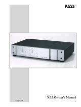
4 Introduction to Advanced Harmonic Filters
4.1 Operation Principle
The Danfoss Advanced Harmonic Filters (AHF) consist of a
main inductor L
0
and a two-stage absorption circuit with the
inductors
L
1
and L
2
and the capacitors C
1
and C
2
. The
absorption circuit is specially tuned to eliminate harmonics
starting with the 5
th
harmonic and is specific for the
designed supply frequency. Consequently the circuit for
50Hz has different parameters than the circuit for 60Hz.
L
0
L
1
L
2
C
2
C
1
M
AHF
Supply Motor
130BB578.11
Frequency
converter
AHFs are available in two variants for two performance
levels:
AHF005 with 5% THiD (total current harmonic
distortion) and AHF010 with 10% THiD. The strategy behind
the two levels is to offer a performance similar to 12 pulse
rectifiers with the AHF010 and a performance similar to 18
pulse rectifiers with AHF005.
The filter performance in terms of THiD varies as a function
of the load. At nominal load the performance of the filter
should be equal or better than 10% THiD for AHF010 and 5%
THiD for AHF005.
At partial load the THiD has higher values. However, the
absolute value of the harmonic current is lower at partial
loads, even if the THiD has a higher value. Consequently, the
negative effect of the harmonics at partial loads will be lower
than at full load.
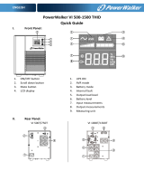
Example:
An 18.5kW frequency converter is installed on a 400V/50Hz
grid with a 34A AHF010 (type code AHF-DA-34-400-50-20-A).
Following values are measured for different load currents,
using a harmonic analyzer:
I line RMS [A] Fundamental
current
at 50Hz
I
1
RMS [A]
THiD [%] Total harmonic
current Ih RMS
[A]
1
9.6 9.59 5.45 0.52
15.24 15.09 13.78 2.07
20.24 20.08 12.46 2.5
25.17 25 11.56 2.89
30.27 30.1 10.5 3.15
34.2 34.03 9.95 3.39
1
)The
total harmonic current has been calculated. The THiD
vs. load plot is shown in the following figure.
AHF-DA-34-400-50-20-A
0
2
4
6
8
10
12
14
16
10 15 20 25 30 35
Iline [A]
THiD [%]
0
0,5
1
1,5
2
2,5
3
3,5
4
Harmonic current Ih [A]
130BB579.10
THiD [%]
Harmonic current Ih [A]
It can be observed that at partial load, 15A, the THiD is
approximately 14%, compared to 10% at the nominal load of
34A.
On the other hand, the total harmonic current is only
2.07A at 15A line current against 3.39A harmonic current at
34A line current. Thus, THiD is only a relative indicator of the
harmonic performance. The harmonic distortion of the
voltage will be less at partial load than at nominal load.
Factors such as background distortion and grid unbalance
can affect the performance of AHF filters. The specific figures
are different from filter to filter and the graphs below show
typical performance characteristics. For specific details a
harmonic design tool such as MCT 31 or Harmonic
Calculation Software (HCS) should be used.
Background distortion: The design of the filters aims to
achieve 10% respectively 5% THiD levels with a background
distortion of THvD = 2%. Practical measurements on typical
grid conditions in installations with frequency converters
show that often the performance of the filter is slightly
better with a 2% background distortion. However, the
complexity of the grid conditions and mix of specific
harmonics can not allow a general rule about the
performance on a distorted grid. Therefore we have chosen
to present worst-case performance deterioration character-
istics with the background distortion.
Introduction to Advanced Ha... AHF005/010 Design Guide
12 MG.80.C4.02 - VLT
®
is a registered Danfoss trademark
44

0 20 40 60 80 100
0
5
10
15
20
25
THvD 0%
THvD 2%
THvD 5%
Load [%]
THiD average [%]
130BB580.10
Illustration 4.1 AHF005
0
10
20
30
40
50
60
0 20 40 60 80 100
Load [%]
THvD 0%
THvD 2%
THvD 5%
THiD [%]
130BB581.10
Illustration 4.2 AHF010
Performance at 10% THvD has not been plotted. However,
the
filters have been tested and can operate at 10% THvD
but the filter performance can no longer be guaranteed.
The filter performance also deteriorates with the unbalance
of the supply. Typical performance is shown in the graphs
below.
0% unbalance
1% unbalance
2% unbalance
3% unbalance
0 20 40 60 80 100
Load [%]
0
2
4
6
8
10
12
14
THiD [%]
130BB582.10
Illustration 4.3 AHF005
130BB583.10
0
0 20 40 60 80 100
Load [%]
5
10
15
20
25
0% unbalance
1% unbalance
2% unbalance
3% unbalance
THiD average [%]
Illustration 4.4 AHF010
4.1.1 Power Factor
In no load conditions (the frequency converter is in stand-by)
the
frequency converter current is negligible and the main
current drawn from the grid is the current through the
capacitors in the harmonic filter. Therefore the power factor
is close to 0, capacitive. The capacitive current is approxi-
mately 25% of the filter nominal current (depends on filter
size, typical values between 20 and 25%). The power factor
increases with the load. Because of the higher value of the
main inductor L
0
in the AHF005, the power factor is slightly
higher than in the AHF010.
Following graphs show typical values for the true power
factor on AHF010 and AHF005.
0
0,1
0,2
0,3
0,4
0,5
0,6
0,7
0,8
0,9
1
0 20 40 60 80 100
Load [%]
True Power Factor
130BB584.10
Illustration 4.5 AHF005
0,1
0,2
0,3
0,4
0,5
0,6
0,7
0,8
0,9
1
0 20 40 60 80 100
Load [%]
0
True Power Factor
130BB585.10
Illustration 4.6 AHF010
Introduction to Advanced Ha... AHF005/010 Design Guide
MG.80.C4.02 - VLT
®
is a registered Danfoss trademark
13
4 4

4.1.2 Capacitor Disconnect
If the specific application requires a higher power factor at
no-load and the reduction of the capacitive current in stand-
by,
a capacitor disconnect should be used. A contactor can
disconnect the capacitor at loads below 20%. It is important
to note that the capacitors may not be connected at full load
or disconnected at no load.
It is very important to consider the capacitive current in the
design of applications where the harmonic filter is supplied
by a generator. The capacitive current can overexcite the
generator in no-load and low-load condition. The over-
excitation causes an increase of the voltage that can exceed
the allowed voltage for the AHF and the frequency
converter. Therefore a capacitor disconnect should always be
used in generator applications and the design carefully
considered.
Compared to multi-pulse rectifiers, passive harmonic filter
(such as AHF) are more robust against background distortion
and supply imbalance. However, the performance of passive
filters is inferior to the performance of active filters when it
comes to partial load performance and power factor. For
details about the performance positioning of the various
harmonic mitigation solutions offered by Danfoss, please
consult the relevant harmonic mitigation literature.
Introduction to Advanced Ha... AHF005/010 Design Guide
14 MG.80.C4.02 - VLT
®
is a registered Danfoss trademark
44

5 Selection of Advanced Harmonic Filter
This chapter will provide guidance about how to choose the
right
filter size and contains calculation examples, electrical
data and the general specification of the filters.
5.1 How to Select the Correct AHF
For optimal performance the AHF should be sized for the
mains
input current to the frequency converter. This is the
input current drawn based on the expected load of the
frequency converter and not the size of the frequency
converter itself.
5.1.1 Calculation of the Correct Filter Size
Needed
The mains input current of the frequency converter (I
FC,L
) can
be calculated using the nominal motor current (I
M,N
) and the
displacement
factor (Cos φ) of the motor. Both values are
normally printed on the name plate of the motor. In case the
nominal motor voltage (U
M,N
) is unequal to the actual mains
voltage (U
L
), the calculated current must be corrected with
the ratio between these voltages as shown in the following
equation:
I
FC
.
L
= 1.1 ×
I
M
,
N
×
cos
(
ρ
)
×
U
M
,
N
U
L
The AHF chosen must have a nominal current (I
AHF,N
) equal to
or larger than the calculated frequency converter mains
input current (I
FC,L
).
NOTE
Do
not oversize the AHF. The best harmonic performance is
obtained at nominal filter load. Using an oversized filter will
most likely result in reduced THiD performance.
If several frequency converters are to be connected to the
same
filter, the AHF must be sized according to the sum of
the calculated mains input currents.
NOTE
If
the AHF is sized for a specific load and the motor is
changed, the current must be recalculated to avoid
overloading the AHF.
5.1.2 Calculation Example
System mains voltage (U
L
): 380V
Motor name plate power(P
M
): 55kW
Motor efficiency (ƞ
M
):
0.96
FC efficiency (ƞ
FC
):
0.97
AHF effiency (ƞ
AHF
)(worst
case estimate):
0.98
Maximum line current (RMS):
P
M
× 1000
U
L
× η
M
× η
FC
× η
AHF
×
3
=
55 × 1000
380 ×
0.96 × 0.97 × 0.98 ×
3
= 91.
57
A
In this case a 96A filter must be chosen.
5.1.3 Voltage Boost
In stand-by and under low condition, the AHFs will boost the
input
voltage with up to 5%. This means that the voltage at
the frequency converter terminals is up to 5% higher than
the voltage at the input of the filter. This should be
considered at the design of the installation. Special care
should be taken in 690V applications, where the voltage
tolerance of the frequency converter is reduced to +5%, the
boost voltage can, at low load and stand-by, be limited via
the available capacitor disconnect. For more information see
section 6.2.2.
Selection of Advanced Harmo... AHF005/010 Design Guide
MG.80.C4.02 - VLT
®
is a registered Danfoss trademark
15
5 5

5.2 Electrical Data
Code number
AHF005
IP00
IP20
Code number
AHF010
IP00
IP20
Filter current
rating
Typical motor VLT power and current
ratings
Losses Acoustic noise Frame size
AHF005 AHF010
A kW kW A W W dBA AHF005 AHF010
130B1392
130B1229
130B1262
130B1027
10 3 PK37-P4K0 1.2-9 131 93 <70 X1 X1
130B1393
130B1231
130B1263
130B1058
14 7.5 P5K5-P7K5 14.4 184 118 <70 X1 X1
130B1394
130B1232
130B1268
130B1059
22 11 P11K 22 258 206 <70 X2 X2
130B1395
130B1233
130B1270
130B1089
29 15 P15K 29 298 224 <70 X2 X2
130B1396
130B1238
130B1273
130B1094
34 18.5 P18K 34 335 233 <72 X3 X3
130B1397
130B1239
130B1274
130B1111
40 22 P22K 40 396 242 <72 X3 X3
130B1398
130B1240
130B1275
130B1176
55 30 P30K 55 482 274 <72 X3 X3
130B1399
130B1241
130B1281
130B1180
66 37 P37K 66 574 352 <72 X4 X4
130B1442
130B1247
130B1291
130B1201
82 45 P45K 82 688 374 <72 X4 X4
130B1443
130B1248
130B1292
130B1204
96 55 P55K 96 747 428 <75 X5 X5
130B1444
130B1249
130B1293
130B1207
133 75 P75K 133 841 488 <75 X5 X5
130B1445
130B1250
130B1294
130B1213
171 90 P90K 171 962 692 <75 X6 X6
130B1446
130B1251
130B1295
130B1214
204 110 P110 204 1080 742 <75 X6 X6
130B1447
130B1258
130B1369
130B1215
251 132 P132 251 1195 864 <75 X7 X7
130B1448
130B1259
130B1370
130B1216
304 160 P160 304 1288 905 <75 X7 X7
130B3153
130B3152
130B3151
130B3136
325 Paralleling for 355kW 1406 952 <75 X8 X7
130B1449
130B1260
130B1389
130B1217
381 200 P200 381 1510 1175 <77 X8 X7
130B1469
130B1261
130B1391
130B1228
480 250 P250 472 1852 1542 <77 X8 X8
Table 5.1 380-415V, 50Hz
Selection of Advanced Harmo... AHF005/010 Design Guide
16 MG.80.C4.02 - VLT
®
is a registered Danfoss trademark
55

Code number
AHF005
IP00
IP20
Code number
AHF010
IP00
IP20
Filter current
rating
Typical motor VLT power and
current ratings
Losses Acoustic noise Frame size
AHF005 AHF010
A kW kW A W W dBA AHF005 AHF010
2 x 130B1448
2 x 130B1259
2 x 130B1370
2 x 130B1216
608 315 P315 590 2576 1810 <80
2 x 130B3153
2 x 130B3152
2 x 130B3151
2 x 130B3136
650 355 P355 647 2812 1904 <80
130B1448 + 130B1449
130B1259 + 130B1260
130B1370 + 130B1389
130B1216 + 130B1217
685 400 P400 684 2798 2080 <80
2 x 130B1449
2 x 130B1260
2 x 130B1389
2 x 130B1217
762 450 P450 779 3020 2350 <80
130B1449 + 130B1469
130B1260 + 130B1261
130B1389 + 130B1391
130B1217 + 130B1228
861 500 P500 857 3362 2717 <80
2 x 130B1469
2 x 130B1261
2 x 130B1391
2 x 130B1228
960 560 P560 964 3704 3084 <80
3 x 130B1449
3 x 130B1260
3 x 130B1389
3 x 130B1217
1140 630 P630 1090 4530 3525 <80
2 x 130B1449 + 130B1469
2 x 130B1260 + 130B1261
2 x 130B1389 + 130B1391
2 x 130B1217 + 130B1228
1240 710 P710 1227 4872 3892 <80
3 x 130B1469
3 x 1301261
3 x 130B1391
3 x 130B1228
1440 800 P800 1422 5556 4626 <80
2 x 130B1449 + 2 x 130B1469
2 x 130B1260 + 2 x 130B1261
2 x 130B1389 + 2 x 130B1391
2 x 130B1217 + 2 x 130B1228
1720 1000 P1000 1675 6724 5434 <80
Table 5.2 380-415V, 50Hz
Selection of Advanced Harmo... AHF005/010 Design Guide
MG.80.C4.02 - VLT
®
is a registered Danfoss trademark
17
5 5

Code number
AHF005
IP00
IP20
Codenumber AHF010
IP00
IP20
Filter current
rating
Typical motor VLT power and current
ratings
Losses Acoustic noise Frame size
AHF005 AHF010
A kW kW A W W dBA AHF005 AHF010
130B3095
130B2857
130B2874
130B2262
10 3 PK37-P4K0 1.2-9 131 93 <70 X1 X1
130B3096
130B2858
130B2875
130B2265
14 7.5 P5K5-P7K5 14.14 184 118 <70 X1 X1
130B3097
130B2859
130B2876
130B2268
22 11 P11K 22 258 206 <70 X2 X2
130B3098
130B2860
130B2877
130B2294
29 15 P15K 29 298 224 <70 X2 X2
130B3099
130B2861
130B3000
130B2297
34 18.5 P18K 34 335 233 <72 X3 X3
130B3124
130B2862
130B3083
130B2303
40 22 P22K 40 396 242 <72 X3 X3
130B3125
130B2863
130B3084
130B2445
55 30 P30K 55 482 274 <72 X3 X3
130B3026
130B2864
130B3085
130B2459
66 37 P37K 66 574 352 <72 X4 X4
130B3127
130B2865
130B3086
130B2488
82 45 P45K 82 688 374 <72 X4 X4
130B3128
130B2866
130B3087
130B2489
96 55 P55K 96 747 427 <75 X5 X5
130B3129
130B2867
130B3088
130B2498
133 75 P75K 133 841 488 <75 X5 X5
130B3130
130B2868
130B3089
130B2499
171 90 P90K 171 962 692 <75 X6 X6
130B3131
130B2869
130B3090
130B2500
204 110 P110 204 1080 743 <75 X6 X6
130B3132
130B2870
130B3091
130B2700
251 132 P132 251 1194 864 <75 X7 X7
130B3133
130B2871
130B3092
130B2819
304 160 P160 304 1288 905 <75 X7 X7
130B3157
130B3156
130B3155
130B3154
325 Paralleling for 355kW 1406 952 <75 X8 X7
130B3134
130B2872
130B3093
130B2855
381 200 P200 381 1510 1175 <77 X8 X8
130B3135
130B2873
130B3094
130B2856
480 250 P250 472 1850 1542 <77 X8 X8
Table 5.3 380-415V, 60Hz
Selection of Advanced Harmo... AHF005/010 Design Guide
18 MG.80.C4.02 - VLT
®
is a registered Danfoss trademark
55

Code number AHF005
IP00
IP20
Codenumber AHF010
IP00
IP20
Filter current
rating
Typical
motor
VLT power and current
ratings
Losses Acoustic noise Frame size
AHF005 AHF010
A kW kW A W W dBA AHF005 AHF010
2 x 130B3133
2 x 130B2871
2 x 130B3092
2 x 130B2819
608 315 P315 590 2576 1810 <80
2 x 130B3157
2 x 130B3156
2 x 130B3155
2 x 130B3154
650 315 P355 647 2812 1904 <80
130B3133 + 130B3134
130B2871 + 130B2872
130B3092 + 130B3093
130B2819 + 130B2855
685 355 P400 684 2798 2080 <80
2 x 130B3134
2 x 130B2872
2 x 130B3093
2 x 130B2855
762 400 P450 779 3020 2350 <80
130B3134 + 130B3135
130B2872 + 130B3135
130B3093 + 130B3094
130B2855 + 130B2856
861 450 P500 857 3362 2717 <80
2 x 130B3135
2 x 130B2873
2 x 130B3094
2 x 130B2856
960 500 P560 964 3704 3084 <80
3 x 130B3134
3 x 130B2872
3 x 130B3093
3 x 130B2855
1140 560 P630 1090 4530 3525 <80
2 x 130B3134 + 130B3135
2 x 130B2872 + 130B2873
2 x 130B3093 + 130B3094
2 x 130B2855 + 130B2856
1240 630 P710 1227 4872 3892 <80
3 x 130B3135
3 x 130B2873
3 x 130B3094
3 x 130B2856
1440 710 P800 1422 5556 4626 <80
2 x 130B3134 + 2 x 130B3135
2 x 130B2872 + 2 x 130B2873
2 x 130B3093 + 2 x 130B3094
2 x 130B2855 + 2 x 130B2856
1722 800 P1M0 1675 6724 5434 <80
Table 5.4 380-415V, 60Hz
Selection of Advanced Harmo... AHF005/010 Design Guide
MG.80.C4.02 - VLT
®
is a registered Danfoss trademark
19
5 5

Code number
AHF005
IP00
IP20
Codenumber
AHF010
IP00
IP20
Filter current
rating
Typical motor VLT power and current
ratings
Losses Acoustic noise Frame size
AHF005 AHF010
A HP HP A W W dBA AHF005 AHF010
130B1787
130B1752
130B1770
130B1482
10 4 PK37-P4K0 1-7.4 131 93 <70 X1 X1
130B1788
130B1753
130B1771
130B1483
14 10 P5K5-P7K5 9.9+13 184 188 <70 X1 X1
130B1789
130B1754
130B1772
130B1484
19 15 P11K 19 258 206 <70 X2 X2
130B1790
130B1755
130B1773
130B1485
25 20 P15K 25 298 224 <70 X2 X2
130B1791
130B1756
130B1774
130B1486
31 25 P18K 31 335 233 <72 X3 X3
130B1792
130B1757
130B1775
130B1487
36 30 P22K 36 396 242 <72 X3 X3
130B1793
130B1758
130B1776
130B1488
48 40 P30K 47 482 374 <72 X3 X3
130B1794
130B1759
130B1777
130B1491
60 50 P37K 59 574 352 <72 X4 X4
130B1795
130B1760
130B1778
130B1492
73 61 P45K 73 688 374 <72 X4 X4
130B1796
130B1761
130B1779
130B1493
95 75 P55K 95 747 428 <75 X5 X5
130B1797
130B1762
130B1780
130B1494
118 100 P75K 118 841 488 <75 X5 X5
130B1798
130B1763
130B1781
130B1495
154 125 P90K 154 962 692 <75 X6 X6
130B1799
130B1764
130B1782
130B1496
183 150 P110 183 1080 743 <75 X6 X6
130B1900
130B1765
130B1783
130B1497
231 200 P132 231 1194 864 <75 X7 X7
130B2200
130B1766
130B1784
130B1498
291 250 P160 291 1288 905 <75 X7 X7
130B2257
130B1768
130B1785
130B1499
355 300 P200 348 1406 952 <75 X8 X8
130B3168
130B3167
130B3166
130B3165
380 1510 1175 <77 X8 X7
130B2259
130B1769
130B1786
130B1751
436 350 P250 436 1852 1542 <77 X8 X7
Table 5.5 440-480V, 60Hz
Selection of Advanced Harmo... AHF005/010 Design Guide
20 MG.80.C4.02 - VLT
®
is a registered Danfoss trademark
55
/