Danfoss VLT AutomationDrive FC 301 Operating instructions

Type
Operating instructions
Contents
1 Safety
3
Warnings 3
Symbols Used in This Manual 3
Operator's Safety 3
Avoid Filter Module Damage 4
2 Ordering Numbers
5
Description 5
Ordering Numbers, 380 - 415V, 50Hz 6
Ordering Numbers, 380 - 415V, 60Hz 6
Ordering Numbers, 440 - 480V, 60Hz 7
Ordering Numbers, 500 - 525V, 50Hz 7
Ordering Numbers, 690V, 50Hz 8
Calculation of the Exact Filter Size Needed 8
3 Specifications
9
General Technical Data 9
Environmental Data 9
Dimensions/Weight 10
Dimension Diagrams 11
4 Installation
15
Mechanical Installation 15
Ventilation 16
Cable lengths and cross sections 16
Capacitor Disconnect 18
Fuses 21
Over Temperature Switch 22
Operation on Different Mains Type 23
Typical Installation in a Panel or Other Enclosures 23
5 Commissioning
25
6 Appendix: Safety and Application Notes
27
General 27
Application as Directed 27
Transport and Storage 27
Installation 27
Electrical Installation 28
Operation 28
Maintenance and Service 28
AHF 005/010 Operating Instructions Contents
MG.80.C2.02 - VLT
®
is a registered Danfoss trademark
1
Index
29
Contents AHF 005/010 Operating Instructions
2
MG.80.C2.02 - VLT
®
is a registered Danfoss trademark
1Safety
1.1.1 Warnings
The Danfoss harmonic filter AHF 005 and AHF 010 contain dangerous voltages when connected to mains voltages. Only a competent
electrician should carry out the electrical installation. Improper installation of the filter or the connected frequency converter may cause
equipment failure, serious injury or death. Follow this manual and install according to National Electrical Codes and local safety codes.
Operation of the harmonic filter is only allowed when the filters housing lid, door or cover is closed.
1.1.2 Symbols Used in This Manual
This manual contains different symbols that require special attention. The symbols used are the following:
Warning of hazardous electrical voltage.
Warning of a general danger.
NB!
This note designates general, useful notes. If you observe it, handling of the filter/drive system is made easier.
1.1.3 Operator's Safety
After mains disconnections, the power terminals X1.1, X1.2, X1.3, X3.1, X3.2, X3.3, X4.1, X4.2 and X4.3 remain live for minimum 4
minutes.
The filters have to be installed in a way, that they fulfil their function and don’t expose persons to danger. They have to be mounted
correctly and used in accordance with their purpose.
AB terminals are not Protected Extra Low Voltage (PELV).
AHF 005/010 Operating Instructions 1 Safety
MG.80.C2.02 - VLT
®
is a registered Danfoss trademark
3
1
1.1.4 Avoid Filter Module Damage
1. The filter modules may only be used with Danfoss frequency converters.
2. Do not use the drive system (frequency converter, motor load and filter) if the equipment has been damaged.
3. Modifications of the filters are not allowed.
1 Safety AHF 005/010 Operating Instructions
4
MG.80.C2.02 - VLT
®
is a registered Danfoss trademark
1
2Ordering Numbers
2.1.1 Description
The Danfoss harmonic filters AHF 005 and AHF 010 are ensuring near sinusoidal mains current, minimising the harmonic current emission into the mains
supply. The Danfoss AHF 005 and AHF 010 are advanced harmonic filters not to be compared with traditional harmonic trap filters. The Danfoss harmonic
filters have been specially designed to match all the Danfoss frequency converters. The filters AHF 010 and AHF 005 are available in five voltage versions.
380 - 415 V AC, 50 Hz
380 - 415 V AC, 60 Hz
440 - 480 V AC, 60 Hz
500 - 525 V AC, 50 Hz
690 V AC, 50 Hz
The Danfoss AHF 010 and AHF 005 have the following characteristics:
Small compact housing that fits into a panel
Easy to use in retrofit applications
AHF 010 reduces the total harmonic current distortion to 10%*
AHF 005 reduces the total harmonic current distortion to 5%*
Current rating from 10A - 370A
AHF Filters can be paralleled for higher power modules
One filter module can be used for several frequency converters
High efficiency (> 0.98)
User-friendly commissioning - no adjustment necessary
No routine maintenance required
* THiD of 10% or 5% will be achieved when the following conditions are met:
- THvD of the system without the drive operating is less than 2%
- Filter is operating at nominal load
If these conditions are not fulfilled, a significant reduction of the harmonic distortion can still be achieved, but the rated THiD values may not be achieved.
The mains quality has to be according to EN61000-2-4 level 3, allowing a maximum THvD level of 10%.
Illustration 2.1: Principle connection diagram of the AHF harmonic filter.
U
L
: Mains voltage
I
AHF
: Input current of the filter AHF
I
FC,L
: Input current to the frequency converter
I
M
: Motor current
Table 2.1: Legends (as used throughout this manual):
AHF 005/010 Operating Instructions 2 Ordering Numbers
MG.80.C2.02 - VLT
®
is a registered Danfoss trademark
5
2
2.1.2 Ordering Numbers, 380 - 415V, 50Hz
Danfoss Frequency converter series * Ordering Number
I
AHF,N
AQUA, HVAC,
Automation HO
Automation NO AHF 005 AHF 010 [AMP]
PK37 - P4K 175G6600 175G6622 10 A
P5K5 - P7K5 175G6601 175G6623 19 A
P11K 175G6602 175G6624 26 A
P15K-P18K P11K-P15K 175G6603 175G6625 35 A
P22K P18K 175G6604 175G6626 43 A
P30K-P37K P22K-P30K 175G6605 175G6627 72 A
P45K-P55K P37K-P45K 175G6606 175G6628 101 A
P75K P55K 175G6607 175G6629 144 A
P90K P75K 175G6608 175G6630 180 A
P110 P90K 175G6609 175G6631 217 A
P132 P110 175G6610 175G6632 289 A
P160 P132 175G6611 175G6633 324 A
P200 P160 175G6688 175G6691 370 A
P250 P200 175G6609 + 175G6610 175G6631 + 175G6632 506 A
P315 P250 2 x 175G6610 2 x 175G6632 578 A
P355 P315 2 x 175G6611 2 x 175G6633 648 A
Table 2.2: AHF 005 and AHF 010, 380V - 415V, 50Hz
Please note that the matching of the typical Danfoss frequency converter and filter is pre-calculated based on 400V and assuming typical motor
load (4 or 2 pole motor). (FC 300 is based on an 160% torque application, while FC 100 and FC 200 Series are based on 110% torque application.)
The pre-calculated filter current may be different than the input current ratings of FC 100, FC 200 and FC 300 series as stated in the respective
operating instructions, as these numbers are based on different operating conditions.
2.1.3 Ordering Numbers, 380 - 415V, 60Hz
Danfoss Frequency converter series * Ordering Number
I
AHF,N
AQUA, HVAC,
Automation HO
Automation NO AHF 005 AHF 010 [AMP]
PK37-P4K 130B2540 130B2541 10 A
P5K5 - P7K5 130B2460 130B2472 19 A
P11K 130B2461 130B2473 26 A
P15K-P18K P11K-P15K 130B2462 130B2474 35 A
P22K P18K 130B2463 130B2475 43 A
P30K-P37K P22K-P30K 130B2464 130B2476 72 A
P45K-P55K P37K-P45K 130B2465 130B2477 101 A
P75K P55K 130B2466 130B2478 144 A
P90K P75K 130B2467 130B2479 180 A
P110 P90K 130B2468 130B2480 217 A
P132 P110 130B2469 130B2481 289 A
P160 P132 130B2470 130B2482 324 A
P200 P160 130B2471 130B2483 370 A
P250 P200 130B2468 + 130B2469 130B2480 + 130B2481 506 A
P315 P250 2 x 130B2469 2 x 130B2481 578 A
P355 P315 2 x 130B2470 2 x 130B2482 648 A
Table 2.3: AHF 005 and AHF 010, 380V - 415V, 60Hz
Please note that the matching of the typical Danfoss frequency converter and filter is pre-calculated based on 400V and assuming typical motor
load (4 or 2 pole motor). (FC 300 is based on an 160% torque application, while FC 100 and FC 200 Series are based on 110% torque application.)
The pre-calculated filter current may be different than the input current ratings of FC 100, FC 200 and FC 300 series as stated in the respective
operating instructions, as these numbers are based on different operating conditions.
2 Ordering Numbers AHF 005/010 Operating Instructions
6
MG.80.C2.02 - VLT
®
is a registered Danfoss trademark
2
2.1.4 Ordering Numbers, 440 - 480V, 60Hz
Danfoss Frequency Converter Series * Ordering Number
I
AHF,N
AQUA, HVAC,
Automation HO
Automation NO AHF 005 AHF 010 [AMP]
PK37-P7K5 130B2538 130B2539 10 A
P11K 175G6612 175G6634 19 A
P15K P11K 175G6613 175G6635 26 A
P18K-P22K P15K 175G6614 175G6636 35 A
P30K P18K-P22K 175G6615 175G6637 43 A
P37K-P45K P30K-P37K 175G6616 175G6638 72 A
P55K P45K 175G6617 175G6639 101 A
P75K-P90K P55K-P75K 175G6618 175G6640 144 A
P110K P90K 175G6619 175G6641 180 A
P132 P110 175G6620 175G6642 217 A
P160 P132 175G6621 175G6643 289 A
P200 P160 175G6689 175G6692 324 A
175G6690 175G6693 370 A
P250 P200 2 x 175G6620 2 x 175G6642 434 A
P315-P355 P250-P315 2 x 175G6621 2 x 175G6643 578 A
P400 P355 175G6690 + 175G6621 175G6693 + 175G6643 659 A
Table 2.4: AHF005 and AHF010, 440 - 480V, 60Hz
Please note that the matching of the typical Danfoss frequency converter and filter is pre-calculated based on 480V and assuming typical motor
load. FC 300 is based on an 160% torque application, while FC 100 and FC 200 series are based on 110% torque application.
The pre-calculated filter current may be varying from the input current ratings of FC 100, FC 200 and FC 300 series as stated in the respective
operating instructions, as these numbers are based on different operating conditions.
2.1.5 Ordering Numbers, 500 - 525V, 50Hz
Danfoss Frequency Converter Series * Ordering Number
I
AHF,N
AQUA, HVAC,
Automation HO
Automation NO AHF 005 AHF 010 [AMP]
PK75-P5K5 175G6644 175G6656 10 A
P7K5-P11K 175G6645 175G6657 19 A
P15K-P18K P11K-P15K 175G6646 175G6658 26 A
P22K P18K 175G6647 175G6659 35 A
P30K P22K 175G6648 175G6660 43 A
P37K-P45K P30K-P37K 175G6649 175G6661 72 A
P55K-P75K P45K-P55K 175G6650 175G6662 101 A
P90K-P110 P75K-P90K 175G6651 175G6663 144 A
P132 P110 175G6652 175G6664 180 A
P160 P132 175G6653 175G6665 217 A
P200 P160 175G6654 175G6666 289 A
P250 P200 175G6655 175G6667 324 A
P315-P400 P250-P315 2 x 175G6653 2 x 175G6665 370 A
P355 175G6652 + 175G6654 175G6664 + 175G6666 506 A
P500-P560 P400-P500 2 x 175G6654 2 x 175G6666 578 A
Table 2.5: AHF005 and AHF 010, 500-525V, 50Hz
AHF 005/010 Operating Instructions 2 Ordering Numbers
MG.80.C2.02 - VLT
®
is a registered Danfoss trademark
7
2
Please note that the matching of the typical Danfoss frequency converter and filter is pre-calculated based on 500V and assuming typical motor
load. FC 300 is based on an 160% torque application, while FC 100 and FC 200 series are based on 110% torque application.
The pre-calculated filter current may be varying from the input current ratings of FC 100, FC 200 and FC 300 series as stated in the respective
operating instructions, as these numbers are based on different operating conditions.
2.1.6 Ordering Numbers, 690V, 50Hz
Danfoss Frequency Converter Series * Ordering Number
I
AHF,N
AQUA, HVAC,
Automation HO
Automation NO AHF 005 AHF 010 [AMP]
130B2328 130B2293 43 A
P37K-P45K P37K 130B2330 130B2295 72 A
P55-P75K P45K-P55K 130B2331 130B2296 101 A
P90K-P110 P75K-P90K 130B2333 130B2298 144 A
P132 P110 130B2334 130B2299 180 A
P160 P132 130B2335 130B2300 217 A
P200 P160 130B2331 + 130B2333 130B2301 289 A
P250 P200 130B2333 + 130B2334 130B2302 324 A
P315 P250 130B23314+ 130B2335 130B2304 370 A
Table 2.6: AHF005 and AHF010, 690V, 50Hz
Please note that the matching of the typical Danfoss frequency converter and filter is pre-calculated based on 690V and assuming typical motor
load. FC 300 is based on an 160% torque application, while FC 100 and FC 200 series are based on 110% torque application.
The pre-calculated filter current may be varying from the input current ratings of FC 100, FC 200 and FC 300 series as stated in the respective
operating instructions, as these numbers are based on different operating conditions.
2.1.7 Calculation of the Exact Filter Size Needed
NB!
For optimal performance the harmonic filter should be sized for the mains input current to the frequency converter, i.e. the input current
drawn based on the expected load of the frequency converter and not the size of the frequency converter itself!
The mains input current to the frequency converter (I
FC,L
) can by calculated using the nominal motor current (I
M,N
) and displacement power factor (Cos
φ)) of the motor. Both data are normally printed on the nameplate of the motor. In the case where the nominal motor voltage (U
M,N
) is unequal to the
actual mains-mains voltage (U
L
) the calculated current must be corrected with the ratio between these voltages as shown in the equation below.
I
FC
,
L
= 1.1 ×
I
M
,
N
×
Cos
(
ϕ
)
×
((
U
M
,
N
)
/
(
U
L
))
The harmonic filter chosen must have a nominal current (I
AHF,N
) equal to or larger than the calculated frequency converter mains input current (I
FC,L
).
If several frequency converters are to be connected to the same filter, the harmonic filter must be sized according to the sum of the calculated mains
currents.
If the harmonic filter is sized for the load, and the motor of the corresponding frequency converter is changed, the current must be
re-calculated to avoid overload of the harmonic filter.
2 Ordering Numbers AHF 005/010 Operating Instructions
8
MG.80.C2.02 - VLT
®
is a registered Danfoss trademark
2
3Specifications
3.1.1 General Technical Data
AHF 0xx AHF 0xx AHF 0xx AHF 0xx AHF 0xx
Nominal supply
voltage
U
L,N
[V] 380 U
L,N
415 380 U
L,N
415 440 U
L,N
480 500 V 690 V
Tolerance of the ac-
tual supply voltage
U
L
[V] 342 U
L
456 342 U
L
456 396 U
L
528 450 U
L
550 621 U
L
759
Supply frequency f
L,N
[Hz] 50 ± 5 % 60 ± 5 % 60 ± 5 % 50 ± 5 % 50 ± 5 %
Overload capability 1,6 for 60s
Efficiency η[%] ~ 98.8 %
THiD [%] AHF 005 < 5%
AHF 010 < 10%
cos φ of I
L
0.5 cap
0.8 cap
0.85 cap
0.99 cap
1.00
at 25% I
AHF,N
at 50% I
AHF,N
at 75% I
AHF,N
at 100% I
AHF,N
at 150% I
AHF,N
Power derating [%/C]
[%/m]
40°C < Ta < 55°C => 3%/C
1000m altitude above sea level.< h 2500m altitude above sea level => 5%/1000m
NB!
The reduction of the low harmonic current emission to the rated THiD implies, that the THvD of the non-influenced mains voltage is
lower than 2% and the ratio of short circuit power to installed load (R
SCE
) is at least 66. Under these conditions the THiD of the mains
current of the frequency converter is reduced to 10% or 5% (typical values at nominal load). If these conditions are not or only partially
fulfilled, a significant reduction of the harmonic components can still be achieved, but the rated THiD values may not be achieved.
3.1.2 Environmental Data
Permissible
temperature range*
During transport of the unit:
During storage of the unit:
During operation of the unit:
-25°C...+70°C (to EN 50178)
-25°C...+55°C (to EN 50178)
5°C...+40°C without power derating
5°C...+55°C with power derating
Humidity class* Humidity class F without condensation ( 5% - 85% relative humidity)
Installation height h*
H 1000 m altitude above sea level
1000 m < h 2500 m altitude above sea level
without power derating
with power derating
Degree of pollution VDE 0110 Part 2 degree 2
Insulation strength Overvoltage category III according to VDE 0110
Packaging DIN 55468 for transport packaging materials
Type of protection IP 20
Approvals CE: Low-Voltage Directive; UL
Table 3.1: Environmental data
*climatic conditions according to class 3K3 (EN 50178 Part 6.1)
AHF 005/010 Operating Instructions 3 Specifications
MG.80.C2.02 - VLT
®
is a registered Danfoss trademark
9
3
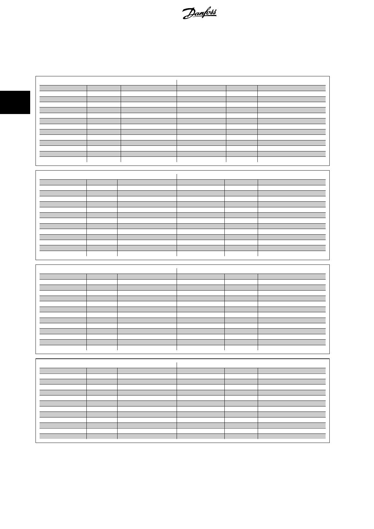
3.1.3 Dimensions/Weight
The AHF modules are available in seven frame sizes (size B to H).
For dimensions see the drawings on the following pages
AHF 005, 380 – 415 V AC, 50Hz AHF 010, 380– 415 V AC, 50Hz
I
AHF,N
Frame size Weight I
AHF,N
Frame size Weight
10 A B 20 Kg (44 lbs) 10 A B 15 Kg (33 lbs)
19 A C 31 Kg (68 lbs) 19 A B 19 Kg (42 lbs)
26 A C 31 Kg (68 lbs) 26 A B 24 Kg (52 lbs)
35 A C 49 Kg (108 lbs) 35 A C 38 Kg (84 lbs)
43 A D 60 Kg (132 lbs) 43 A C 45 Kg (99 lbs)
72 A D 81 Kg (178 lbs) 72 A D 64 Kg (141 lbs)
101 A E 128 Kg (282 lbs) 101 A D 80 Kg (176 lbs)
144 A E 165 Kg (364 lbs) 144 A D 101 Kg (222 lbs)
180 A F 197 Kg (434 lbs) 180 A E 134 Kg (295 lbs)
217 A F 228 Kg (503 lbs) 217 A E 159 Kg (350 lbs)
289 A G 269 Kg (593 lbs) 289 A F 180 Kg (396 lbs)
324 A G 309 Kg (681 lbs) 324 A F 233 Kg (513 lbs)
370 A H 345 Kg (760 lbs) 370 A G 252 Kg (555 lbs)
AHF 005, 380 – 415 V AC, 60Hz AHF 010, 380 – 415 V AC, 60Hz
I
AHF,N
Frame size Weight I
AHF,N
Frame size Weight
10 A B 20 kg (44 lbs) 10 A B 15 kg (33 lbs)
19 A C 32 kg (71 lbs) 19 A B 20 kg (44 lbs)
26 A C 43 kg (95 lbs) 26 A B 25 kg (55 lbs)
35 A C 50 kg (110 lbs) 35 A C 38 kg (84 lbs)
43 A D 60 kg (132 lbs) 43 A C 45 kg (99 lbs)
72 A D 82 kg (181 lbs) 72 A D 64 kg (141 lbs)
101 A E 129 kg (284 lbs) 101 A D 81 kg (178 lbs)
144 A E 167 kg (368 lbs) 144 A D 103 kg (227 lbs)
180 A F 200 kg (441 lbs) 180 A E 135 kg (297 lbs)
217 A F 230 kg (507 lbs) 217 A E 161 kg (355 lbs)
289 A G 272 kg (600 lbs) 289 A F 191 kg (421 lbs)
324 A G 306 kg (675 lbs) 324 A F 232 kg (511 lbs)
370 A H 348 kg (767 lbs) 370 A G 245 kg (540 lbs)
AHF 005, 440 – 480 V AC, 60Hz AHF 010, 440 – 480 V AC, 60Hz
I
AHF,N
Frame size Weight I
AHF,N
Frame size Weight
10 A B 20 kg (44 lbs) 10 A B 15 kg (33 lbs)
19 A C 32 kg (71 lbs) 19 A B 20 kg (44 lbs)
26 A C 43 kg (95 lbs) 26 A B 25 kg (55 lbs)
35 A C 50 kg (110 lbs) 35 A C 38 kg (84 lbs)
43 A D 60 kg (132 lbs) 43 A C 45 kg (99 lbs)
72 A D 82 kg (181 lbs) 72 A D 64 kg (141 lbs)
101 A E 129 kg (284 lbs) 101 A D 81 kg (178 lbs)
144 A E 167 kg (368 lbs) 144 A D 103 kg (227 lbs)
180 A F 200 kg (441 lbs) 180 A E 135 kg (297 lbs)
217 A F 230 kg (507 lbs) 217 A E 161 kg (355 lbs)
289 A G 272 kg (600 lbs) 289 A F 191 kg (421 lbs)
324 A G 306 kg (675 lbs) 324 A F 232 kg (511 lbs)
370 A H 348 kg (767 lbs) 370 A G 245 kg (540 lbs)
AHF 005, 500 - 525 V AC, 50Hz AHF 010, 500 - 525 V AC, 50Hz
I
AHF,N
Frame size Weight I
AHF,N
Frame size Weight
10 A B 22 Kg (48 lbs) 10 A B 17 Kg (37 lbs)
19 A C 35 Kg (77 lbs) 19 A B 21 Kg (46 lbs)
26 A C 49 Kg (108 lbs) 26 A B 28 Kg (62 lbs)
35 A C 55 Kg (121 lbs) 35 A C 42 Kg (93 lbs)
43 A D 67 Kg (147 lbs) 43 A D 47 Kg (104 lbs)
72 A E 82 Kg (181 lbs) 72 A D 69 Kg (152 lbs)
101 A E 144 Kg (317 lbs) 101 A D 91 Kg (200 lbs)
144 A E 187 Kg (412 lbs) 144 A E 131 Kg (289 lbs)
180 A F 226 Kg (498 lbs) 180 A E 147 Kg (324 lbs)
217 A F 262 Kg (578 lbs) 217 A F 185 Kg (408 lbs)
289 A G 309 Kg (681 lbs) 289 A F 209 Kg (461 lbs)
324 A G 348 Kg (767 lbs) 324 A G 256 Kg (564 lbs)
3 Specifications AHF 005/010 Operating Instructions
10
MG.80.C2.02 - VLT
®
is a registered Danfoss trademark
3
AHF 005, 690V AC, 50Hz AHF 010, 690 V AC, 50Hz
I
AHF,N
Frame size Weight I
AHF,N
Frame size Weight
43 A D 85 kg (187 lbs) 43 A D 65 kg (143 lbs)
72 A E 100 kg (220 lbs) 72 A D 75 kg (165 lbs)
101 A F 130 kg (287 lbs) 101 A E 95 kg (209 lbs)
144 A G 160 kg (353 lbs) 144 A E 125 kg (275 lbs)
180 A G 200 kg (441 lbs) 180 A F 140 kg (309 lbs)
217 A H 300 kg (661 lbs) 217 A G 180 kg (397 lbs)
289 A G 200 kg (441 lbs)
324 A H 250 kg (551 lbs)
370 A H 300 kg (661 lbs)
3.1.4 Dimension Diagrams
Illustration 3.1: Frame size B
Illustration 3.2: Frame size C
AHF 005/010 Operating Instructions 3 Specifications
MG.80.C2.02 - VLT
®
is a registered Danfoss trademark
11
3
Illustration 3.3: Frame size D
Illustration 3.4: Frame size E
3 Specifications AHF 005/010 Operating Instructions
12
MG.80.C2.02 - VLT
®
is a registered Danfoss trademark
3
Illustration 3.5: Frame size F
Illustration 3.6: Frame size G
AHF 005/010 Operating Instructions 3 Specifications
MG.80.C2.02 - VLT
®
is a registered Danfoss trademark
13
3
Illustration 3.7: Frame size H
Illustration 3.8: Detailed drawing of mounting feet.
NB!
Please allow an additional 30 mm of depth of the filter for the mounting feet.
NB!
Filter frame E-H should only be transported upright, i.e. by using the lifting hooks.
3 Specifications AHF 005/010 Operating Instructions
14
MG.80.C2.02 - VLT
®
is a registered Danfoss trademark
3
4Installation
4.1.1 Mechanical Installation
The encapsulation of the filters have an IP 20 rating. The filters can be
mounted side by side with 60 mm (2,36 inches) clearance.
To other components and to the cabinet walls keep a horizontal clearance
of at least 70 mm (2,76 inches) and a vertical clearance of at least 150
mm (5,91 inches).
Only vertical installation is allowed (mains terminal at bottom).
For versions with bus bars (frame size E H) it is nec-
essary to mount the added covers to the connectors in
order to achieve the protection type IP 20.
Illustration 4.1: Clearance surrounding the AHF filter
Below picture series shows mounting principles. All filters in frame E to H have to be mounted with an added terminal kit to comply with IP20 enclosure
rating. Please make sure that the terminal plastic cover back plate (see photo below) is mounted and fixed correctly before adding the terminal cover.
AHF 005/010 Operating Instructions 4 Installation
MG.80.C2.02 - VLT
®
is a registered Danfoss trademark
15
4
NB!
Unit does not comply with IP20 rating if plastic back plate or terminal cover is omitted.
4.1.2 Ventilation
The filters are cooled by means of air circulation. Consequently, the air needs to be able to move freely above and below the filter module. The efficiency
of the filter modules is greater than 0.98. When installing a filter module in a panel or another enclosure, ensure there is sufficient airflow though the
enclosure to limit heat rise in the enclosure.
AHF 0xx, 380 – 415V,
50 Hz
Max. Heat
AHF 0xx, 380 – 415V,
60 Hz
Max. Heat
AHF 0xx, 440 – 480V,
60 Hz
Max. Heat
AHF 0xx, 500V - 525V,
50 Hz
Max. Heat
AHF 0xx, 690V, 50 Hz
Max. Heat
10 A 83 W 104 W
19 A 158 W 190 W 190 W 197 W
26 A 216 W 259 W 259 W 270 W
35 A 290 W 349 W 349 W 364 W
43 A 358 W 429 W 429 W 447 W 617 W
72 A 599 W 718 W 718 W 748 W 1033 W
101 A 840 W 1008 W 1008 W 1050 W 1448 W
144 A 1197 W 1437 W 1437 W 1496 W 2065 W
180 A 1496 W 1796 W 1796 W 1871 W 2581 W
217 A 1804 W 2165 W 2165 W 2255 W 3112 W
289 A 2403 W 2883 W 2883 W 3003 W 4145 W
324 A 2694 W 3232 W 3232 W 3367 W 4646 W
370 A 3076 W 3691 W 3691 W 5306 W
Table 4.1: Max. heat losses at full load under-voltage.
NB!
If other heat sources (e.g. Danfoss frequency converters) are installed in an enclosure with the harmonic filter AHF 0xx, this heat
generation must also be considered when calculating required airflow
NB!
If the cooling air is polluted (dust, dirt swirl, grease, aggressive gas) the function of the filter module may be impeded. Ensure sufficient
countermeasures, e.g. separate cooling air, mounting of air filters, periodical cleaning.
4.1.3 Cable lengths and cross sections
The installation of our frequency converters in combination with AHF filters allow for a high freedom of installation flexibility. Cable cross section has to
be in accordance with data in the table below and cable lenght has to be limited to 50 meters. It is adviced to use unscreened cables between the AHF
filter and the drive.
Power wiring
Standard connection
Supply voltage must be connected to the terminals X1.1, X1.2 and X1.3. The frequency converter supply terminals L1, L2 and L3 must be connected to
the filter module terminals X2.1, X2.2 and X2.3.
Paralleling of FC's
If several frequency converters are to be connected to the harmonic filter, the connection is similar to the standard connection - The supply terminals
L1, L2 and L3 of several frequency converters must be connected to the filter module terminals X2.1, X2.2 and X2.3.
4 Installation AHF 005/010 Operating Instructions
16
MG.80.C2.02 - VLT
®
is a registered Danfoss trademark
4
NB!
If several VLT frequency converters are to be connected to the same filter, the harmonic filter must be sized according to the sum of
the calculated input current to the VLT frequency converters.
Filters in parallel
If the mains input current of the frequency converter exceeds the nominal current of the largest harmonic filter, several harmonic filters can be paralleled
to achieve the necessary rating. Supply voltage must be connected to the terminals X1.1, X1.2 and X1.3 of the filters. The frequency converter supply
terminals L1, L2 and L3 must be connected to the filter modules terminals X2.1, X2.2 and X2.3.
NB!
Filters of different current ratings can be wired in parallel. The rating of the filter becomes the sum of the individual current ratings.
Power wiring size
Enclosure
Max. cable size mm
2
AWG Type Nom. Fix Torque
[Nm]
B 16 6 Connector 2
C and D 50 1 Connector 6
E * * Bus bars 25
F, G and H * * Bus bars 25
Table 4.2: Power wiring size
Enclosure
Max. cable size mm
2
AWG Type Nom. Fix Torque
[Nm]
B - H 4 Connector 0.6
Table 4.3: Overheat contactor (copper)
NB!
Please consult the drive design guide to find the maximum allowed cable lenght between a terminal protection (PTC) and the drive input.
Enclosure
Max. cable size mm
2
AWG Type Nom. Fix Torque
B 4 10 Connector 0.6 Nm
C and D 16 6 Connector 2 Nm
E, F, G and H 50 1 Connector 6 Nm
Table 4.4: Capacitor disconnect (copper)
NB!
The cable length between the filter and the capacitor disconnect contactor has to be as short as possible in order to reduce the impedance influence
of the cable. A maximum cable lenght of 2 meters are allowed between filter and contactor.
* Power wiring used for connection of the filter AHF 005 and AHF 010 in enclosure size E, F and G must be terminated with cable lugs that can be attached
to the input and output bus bars terminals. This type of termination imposes no specifications of the minimum and maximum cable size suitable for
connection. Power terminal details regarding the bus bars can be found in the figures below.
NB!
Do not fix the nut without using a second wrench for the screw.
If this is not observed, it might be possible to tear out the terminal when fixing the nut.
AHF 005/010 Operating Instructions 4 Installation
MG.80.C2.02 - VLT
®
is a registered Danfoss trademark
17
4
Frame E Frame F Frame G, Frame H
NB!
For UL approval use copper conductor only.
4.1.4 Capacitor Disconnect
The power factor of the harmonic filter AHF 005/010 is decreasing with decreasing load. At zero load the Power Factor becomes zero and the capacitors
produce approximately 30% leading current compared to the rated current of the filter. The reactive current generated by the filter at partial load is
normally not of any concern, mainly because of the small current compared to the system capacity (max. 30%) as well as the fact that other load normally
compensates the capacitive current.
AHF 010
0
0,1
0,2
0,3
0,4
0,5
0,6
0,7
0,8
0,9
1
020406080100
Load [%]
True Power Factor
130BB337.10
Illustration 4.2: Power Factor as a function of load.
In applications where this reactive current may not be accepted, Terminals X3.1, X3.2, X3.3 and X4.1, X4, X4.3 are giving acces to the filter capacitors.
As default (on delivery) the wiring will shorten Terminal X3.1 with X4.1, X3.2 with X4.2 and X3.3 with X.4.3. In the case of that no capacitor disconnect
is required no changes should be made. If capacitor disconnect is required a three-phase contactor should be placed between terminals X3 and X4.
Size the contactor and wiring according to below table. It is recommended only to use contactors with damping resistors.
NB!
It is not allowed to use one common 3 poled contactor in several paralleled AHF at once to disconnect the capacitors.
4 Installation AHF 005/010 Operating Instructions
18
MG.80.C2.02 - VLT
®
is a registered Danfoss trademark
4
380 - 415V 380 - 415V 440 - 480V 500 - 525V 690V
50Hz 60Hz 60Hz 50Hz 50Hz
I
AHF,N
Contactor Rating Contactor Rating Contactor Rating Contactor Rating Contactor Rating
kVAr kVAr kVAr kVAr kVAr
10 A 2 2
19 A 4 5 5 4
26 A 6 7 7 6
35 A 7 9 10 8
43 A 9 11 12 11 16
72 A 15 18 20 18 27
101 A 22 26 27 25 34
144 A 29 35 39 35 50
180 A 37 44 51 46 61
217 A 44 53 69 53 79
289 A 58 70 78 74 101
324 A 66 79 87 85 121
370 A 73 88 99 135
Table 4.5: Capacitor disconnect ratings.
NB!
Only switch the contactor at less than 20% output power. Allow minimum 240 seconds for the capacitors to discharge before turning
on again.
Only use cables complying with local regulations.
AHF 005/010 Operating Instructions 4 Installation
MG.80.C2.02 - VLT
®
is a registered Danfoss trademark
19
4
Illustration 4.3: Connection diagram of filter and frequency converter assembly.
AB terminals are not Protected Extra Low Voltage (PELV).
4 Installation AHF 005/010 Operating Instructions
20
MG.80.C2.02 - VLT
®
is a registered Danfoss trademark
4
  • Page 1 1
  • Page 2 2
  • Page 3 3
  • Page 4 4
  • Page 5 5
  • Page 6 6
  • Page 7 7
  • Page 8 8
  • Page 9 9
  • Page 10 10
  • Page 11 11
  • Page 12 12
  • Page 13 13
  • Page 14 14
  • Page 15 15
  • Page 16 16
  • Page 17 17
  • Page 18 18
  • Page 19 19
  • Page 20 20
  • Page 21 21
  • Page 22 22
  • Page 23 23
  • Page 24 24
  • Page 25 25
  • Page 26 26
  • Page 27 27
  • Page 28 28
  • Page 29 29
  • Page 30 30

Danfoss VLT AutomationDrive FC 301 Operating instructions

Type
Operating instructions

Ask a question and I''ll find the answer in the document

Finding information in a document is now easier with AI