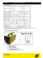
ESAB Origo™Cut 36i User manual
- Category
- Welding System
- Type
- User manual
This manual is also suitable for

Ver 1.0 12/2008
ESAB, Nordic Region
This manual provides service/troubleshooting
instructions for OrigoCut 36i

221
Ver 1.0 12/2008 -2-
ESAB, Nordic Region
Service Manual Ori
g
o
TM
Cut36i Plasma Cuttin
g
S
y
stem
V
er 1.0
Contents
General Precautions..…………………………………………………………………... 3
1. Scope…………………………………………………………………………………… 4
2. Introduction……………………...……………………………………………………. 4
3. Specifications…………………...……………….…………………………………… 5
4. Control Devices and Indicators ……………….………………………………….. 5
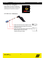
5. PT-31XL Torch – HF Ignition………………….………..………………………….. 6
6. PT-31XL Torch - Maintenance………………………..……………………………. 6
7. Common Cutting Problems…………………………….………………………….. 7
8. Sequence of Operation….………………………………………………………….. 8
9. Block Diagram………………………………………………………………………... 8
10. Main Circuit………………………………………………………………………….. 9
10.1 EMI Filter……………………………………………………………………. 9
10.2 Fan VR1……………………………………………………………………… 9
10.3 Air Solenid Valve SV1…………………………………………………….. 9
10.4 Air Flow Switch S2………………………………………………………… 10
10.5 HF Transformer T2………………………………………………………… 10
10.6 Inverter Board………………………………………………………………. 10
10.7 Secondary Rectifier (Bottom Plate)…………………………………….. 11
10.8 Control Board………………………………………………………………. 11
11. Inverter Board………………………………………………………………………. 12
11.1 PFC and Inrush Current Limiter………………………………………… 12
11.2 Power Stage………………………………………………………………… 13
12. Control Board……………………………………………………………………….. 14
12.1 Power Supply……………………………………………………………….. 14
12.2 Preflow 15 sec. (after the power on)…………………………………….
14
12.3 Preflow 2 sec. (after the start signal)…………………………………… 15
12.4 Start…………………………………………………………………………... 15
12.5 HF Control…………………………………………………………………… 16
12.6 Air Flow Sensing…………………………………………………………… 17
12.7 OCV Control………………………………………………………………… 18
13. Troubleshooting…………………………………………………………………….. 19
14. Spare Parts…………………………………………………………………………... 20

321
Ver 1.0 12/2008 -3-
ESAB, Nordic Region
Service Manual Ori
g
o
TM
Cut36i Plasma Cuttin
g
S
y
stem
V
er 1.0
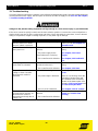
WARNING
ARCWELDING AND CUTTING CAN BE INJURIOUS TO YOURSELF AND OTHERS. TAKE
PRECAUTIONS WHEN WELDING AND CUTTING. ASK FOR YOUR EMPLOYER’S SAFETY PRACTICES
WHICH SHOULD BE BASED ON MANUFACTURER’S HAZARD DATA.
ELECTRIC SHOCK - Can kill
- Install and earth the welding/cutting unit in accordance with applicable standards.
- Do not touch live electrical parts or electrodes with bare skin, wet gloves or wet clothing.
- Insulate yourself from earth and the workpiece.
- Ensure your working distance is safe.
FUMES AND GASES - Can be dangerous to health
- Keep your head away from of the fumes.
- Use ventilation, extraction at the arc, or both, to take fumes and gases away from your
breathing zone and the general area.
ARC RAYS - Can injure eyes and burn skin.
- Protect your eyes and body. Use the correct welding/cutting screen and filter lens and
wear protective clothing.
- Protect bystanders with suitable screens and curtains.
FIREHAZARD
- Sparks (spatter) can cause fire. Make sure there are no inflammable materials
nearby.
NOISE - Excessive noise can damage hearing.
- Protect your ears. Use earmuffs or other hearing protection.
- Warn bystanders of the risk.
MALFUNCTION - Call for expert assistance in the event of malfunction.
READ AND UNDERSTAND THE INSTRUCTION MANUAL BEFORE INSTALLING OR OPERATING!
PROTECT YOURSELF AND OTHERS!
WARNING!
Read and understand the instruction
manual before installing and operating
WARNING! Do not use the power source for thawing frozen pipes.
Note! This product is solely intended for plasma cutting

421
Ver 1.0 12/2008 -4-
ESAB, Nordic Region
Service Manual Ori
g
o
TM
Cut36i Plasma Cuttin
g
S
y
stem
V
er 1.0
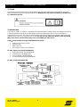
1. Scope
The purpose of this manual is to provide qualified repair personnel with technical information, which will
assist in trobleshooting and repairing malfunctions. Maintenance and repairs should be performed only
by a trained electrician!
2. Introduction
The OrigoCut 36i is a compact, completely self-contained plasma cutting system. As shipped, the system
is fully assembled and ready to cut after being connected to input power and a source of prefiltered
compressed air 5-10 bar. The OrigoCut 36i package uses the PT-31XL torch to deliver cutting power for
materials up to 9 mm or for severing up to 12 mm. Do not use any other torch than PT-31XL torch with
this power source. Serious injury may occur if used with any other torch!
OrigoCut 36i Cutting Package P/N 0558007873 includes:
Power source OrigoCut 36i
PT-31XL torch
Earth cable 5 m
Torch Spare Parts Kit, see list below
PT-31XL Spare Parts Kit P/N 0558003462
3 x 35/40A Nozzle, P/N 0558000508
2 x Electrode, P/N 0558000507
1 x Swirl Baffle, P/N 0558000506
1x Long Heat Shield, P/N 0558000509
PT-31XL Torch P/N 0558001466

521
Ver 1.0 12/2008 -5-
ESAB, Nordic Region
Service Manual Ori
g
o
TM
Cut36i Plasma Cuttin
g
S
y
stem
V
er 1.0
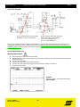
3. Specifications
* The duty cycle refers to the time as a percentage of a ten-minute period that you can weld or cut
at a certain load without overloading the equipment.
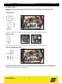
4. Control Devices and Indicators
1. Power On Indicator
2. Output Current Control
3. Air Pressure Indicator
”ON” when the flow switch is closed
4. Over Temperature Indicator
”ON” when the duty cycle has been exceeded
4

621
Ver 1.0 12/2008 -6-
ESAB, Nordic Region
Service Manual Ori
g
o
TM
Cut36i Plasma Cuttin
g
S
y
stem
V
er 1.0
5. PT-31XL Torch – HF Ignition
OrigoCut 36i has a HF type of arc ignition. Arc
strikes when the torch switch is activated and the
cutting tip touches the workpiece or when the HF
strikes between the electrode and workpiece.
6. PT-31XL Torch - Maintenance
Replace the Electrode, when its length is 16 mm.
Replace the Nozzle, when the hole is not round or
performance is poor.
Replace the Heat Shield, when 3 mm has worn-out.
Minimum length 37 mm (new 40 mm).
Check the other parts visually.

721
Ver 1.0 12/2008 -7-
ESAB, Nordic Region
Service Manual Ori
g
o
TM
Cut36i Plasma Cuttin
g
S
y
stem
V
er 1.0
Insufficient Penetration
Uneven Arc
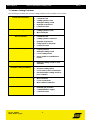
7. Common Cutting Problems
The following list includes the common cutting problems and a probable cause of each.
• Current too low
• Cutting speed too fast
• Damaged cutting nozzle
• Improper air pressure
• Low air flow rate
Main Arc Extinguishes
• Cutting speed too slow
• Worn electrode
Dross Formation
• Current too low
• Cutting speed too fast/slow
• Improper air pressure
• Faulty nozzle or electrode
• Low air flow rate
Double Arcing
• Low air pressure
• Damaged cutting nozzle
• Loose cutting nozzle
• Heavy spatter accumulation on
nozzle
• Damaged cutting nozzle or worn
electrode
Unstable Cutting Conditions
• Incorrect cutting speed
• Loose cable or hose connections
• Electrode and/or cutting nozzle in
poor condition
Main Arc Does Not Strike
• Worn electrode
• Loose connections
• Work cable not attached
Poor Consumable Life
• Improper gas pressure
• Contaminated air supply
• Low air flow rate

821
Ver 1.0 12/2008 -8-
ESAB, Nordic Region
Service Manual Ori
g
o
TM
Cut36i Plasma Cuttin
g
S
y
stem
V
er 1.0
8. Sequence of Operation
NOTE. 1
When the torch switch is closed during the
postflow period, the HF is energized
immediately.
NOTE. 2
If the over temperature light turns on, the
cutting arc is stopped. The postflow time
starts from the moment the torch switch is
released.
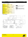
9. Block Diagram

921
Ver 1.0 12/2008 -9-
ESAB, Nordic Region
Service Manual Ori
g
o
TM
Cut36i Plasma Cuttin
g
S
y
stem
V
er 1.0
10. Main Circuit
This section includes the descriptions of the main blocks and separate components of the main
circuit.
10.1 EMI Filter
EMI Filter reduces the conducted electromagnetic disturbances to the distribution network.
10.2 Fan VR1
The cooling fan VR1 (+24V) rotates continuously, when the power source is switched on.
10.3 Air Solenid Valve SV1
After ”power on” the air solenoid valve SV1 (230Vac) is controlled ”on” for approx. 15 sec. (=post flow time)
to purge any moisture or dirt out of the system. When the torch switch is pressed the valve is controlled ”on”
immediately and the preflow time is approx. 2 sec.

1021
Ver 1.0 12/2008 -10-
ESAB, Nordic Region
Service Manual Ori
g
o
TM
Cut36i Plasma Cuttin
g
S
y
stem
V
er 1.0
10.4 Air Flow Switch S2
Regulator
The regulator inside the unit is preset at the factory. When the flow switch S2 closes the green indicator lamp
on the front panel starts to illuminate and the cutting is enabled.
10.5 HF Transformer T2
The HF transformer T2 steps up the primary voltage, which is controlled and generated by a control board.
10.6 Inverter Board
The inverter board (power board) includes the power factor corrector and primary power stage. The power
stage is a dual switch forward inverter and it is built by using parallel connected discrete transistors.
Operating frequency of the inverter is about 64 kHz and the output power is controlled by a PWM principle.
The power factor corrector (PFC) forces the line current to be sinuous and in phase with the line voltage.

1121
Ver 1.0 12/2008 -11-
ESAB, Nordic Region
Service Manual Ori
g
o
TM
Cut36i Plasma Cuttin
g
S
y
stem
V
er 1.0
10.7 Secondary Rectifier (Bottom Plate)
Rectifier
Transformer
Inductor
The secondary voltage of the main transformer T1 is half-wave rectified by the diode D201. Between the
conducting states of the transistors, the secondary current freewheels through the freewheel diodes D202
and D203. The diodes are dumped by the RC-filters. The secondary inductor L2 filters the secondary
current.and prevents the cutting arc to break between the conducting periods of the power transistors.
10.8 Control Board
The control board handles the following control logics:
Start/Stop control
HF control
OCV control
Solenoid valve control
Air flow control
Temperature monitoring
Output control (control loop)
Power supply of the control electronics

1221
Ver 1.0 12/2008 -12-
ESAB, Nordic Region
Service Manual Ori
g
o
TM
Cut36i Plasma Cuttin
g
S
y
stem
V
er 1.0
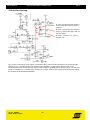
11 Inverter Board
This section includes the detailed description of the inverter board (power board).
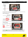
11.1 PFC and Inrush Current Limiter
After ”power on” the ”STARTUNI” limits the initial charging current of the buss capacitors C1A… C1C and
clamps to a safe level the voltage between these. Relay RL1 closes and short circuits the ”STARTUNI” after
the initial charge. When the charging is completed the PFC circuit starts to operate. The PFC forces the line
current to be sinuous and in phase with the line voltage. The PFC circuit lifts up the rectified line voltage to a
level of +380 V.
Picture 1. Picture 2.
Measured across the buss capacitors Measured across the buss capacitors
without damping (full bandwidth) with damping (10kHz, HF reject)
Note. When the voltage across the capacitors
is measured with the standard multimeter,
the meter shows +300 V before the precharge time.
Then the voltage is pulled up to 380Vdc.
Picture 3.
Power on
Initial charge
PFC starts up
Power on
Initial charge
PFC starts up
+380V
+320V

1321
Ver 1.0 12/2008 -13-
ESAB, Nordic Region
Service Manual Ori
g
o
TM
Cut36i Plasma Cuttin
g
S
y
stem
V
er 1.0
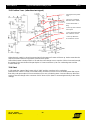
11.2 Power Stage
The operating principle of the power stage is dual switch forward. The upper and lower transistors are
controlled to conducting state at the same time and the voltage on the primary side of the main transformer
T001 rises to the voltage level of the boost converter (+380 V). The magnetization current of the main
transformer returns to the intermediate circuit through the return diodes after the conducting state. The
output power is controlled by adjusting the conducting time of the transistors (PWM). The inverter frequency
is about 64 kHz.
The gating signal of the power transistors is buffered and separated galvanically from the control electronics
by the pulse transformer T1.
Picture 1.
Measured across A3 – A4 during the cutting.
Frequency: 64 kHz
Picture 2.
Measured across A3 – A4 during the cutting.
Voltage: +375 V

1421
Ver 1.0 12/2008 -14-
ESAB, Nordic Region
Service Manual Ori
g
o
TM
Cut36i Plasma Cuttin
g
S
y
stem
V
er 1.0
12. Control Board
This section includes the detailed description of the control board.
12.1 Power Supply
The auxiliary transformer’s T1 (230 Vac / 2 x 8,5 Vac) secondary voltages are full-wave rectified by the
diodes D1, D2, D4 and D5. Zener diode D3 limits the rectified output to a level of +24 V. The regulator U1
regulates the +24 V supply to a level of +12 V.
12.2 Preflow 15 sec. (after power on)
3. Turns up and controls
relay RL1 and solenoid
valve.
2. Turns down.
1. Turns up for a short
time after ”power on”
activating the post flow
delay circuit.
When ”power” source is switched on for a first time, the air preflow (approx. 15 sec.) is activated
automatically. After ”power on” the output of a inverter circuit U2f turns up for a short time and it activates the
post flow delay circuit. The output of inverter U2e turns down and it turns up the output of inverter U2d, which
controls the transistor Q3 to conducting state and the relay RL1 closes and the solenoid valve (230 Vac) is
energized. After the post flow delay (C9 x R20) the solenoid valve will close. During the preflow the inverter
block is off.

1521
Ver 1.0 12/2008 -15-
ESAB, Nordic Region
Service Manual Ori
g
o
TM
Cut36i Plasma Cuttin
g
S
y
stem
V
er 1.0
12.3 Preflow 2 sec. (after the start signal)
Start signal to the power
stage.
5. Q2=non-conducting
when the start is active.
4. Turns down after a
delay.
3. Turns up, the solenoid
valve opens.
2. Turns down when the
torch switch is closed.
1. Turns up when the
torch switch is closed.
When the torch switch is closed (connected to M2) the output of inverter U2f turns up. At the same time the
output of inverter U2d turns up and the solenoid valve opens.
Start of the inverter is delayed (R18 x C6) and when the voltage across capacitor C6 has increased enough,
the output of U2a turns down and optocoupler OC1 turns transistor Q2 to non-conducting state and the
inverter starts up.
12.4 Start
In idle mode the output of the inverter U2a is ”high” and the transistor Q4 is conducting.
When the torch swich is closed (connected to M2), transistor Q4 turns to non-conducting state after a post
flow delay and optocoupler OC1 turns transistor Q2 to non-conducting state > inverter starts up. When the
start is active the voltage at the connector CN2 is about +3,3 V (Note! Connected galvanically to the mains
voltage).

1621
Ver 1.0 12/2008 -16-
ESAB, Nordic Region
Service Manual Ori
g
o
TM
Cut36i Plasma Cuttin
g
S
y
stem
V
er 1.0
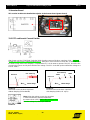
12.5 HF Control
1. The solenoid valve is activated after the torch switch
is pressed.
3. HF circuit is activated when the OCV has exceeded
the treshold value of the zener diodes D17 and D18.
The HF circuit is deactivated when the cutting arc is
established.
2. The inverter is activated after the preflow and the
OCV is present at the output terminals (+280 V).
The HF circuit is activated when the inverter has started and the OCV (+280 V) is present at the output
terminals. When the voltage between the output terminals exceeds the treshold value of the zener diodes
D17 and D18, the HF generator is activated by a relay RL2. Relay RL2 supplies the gating signal for
thyristor Q5, which controls the HF transformer’s primary. The unit does not produce any HF, if the solenoid
valve is not controlled by relay RL1, because the auxiliary transformer T2 is supplied through relay RL1.

1721
Ver 1.0 12/2008 -17-
ESAB, Nordic Region
Service Manual Ori
g
o
TM
Cut36i Plasma Cuttin
g
S
y
stem
V
er 1.0
12.6 Air Flow Sensing
1. Turns up when the flow switch is
closed > the start of the inverter is
enabled.
2. Turns up when the flow switch is
closed > controls the green ”led” on
the front panel.
3. ”High” = Inverter ”on”. ”Low” =
Inverter ”off”.
The air flow is sensed by a flow switch (connected to M1). If the air flow switch does not close during the
preflow (2 sec.), the start signal of the power stage is disabled (= output of the inverter U2b is low).
When the flow switch closes the start signal for the inverter is enabled and the green ”led” DL2 on the front
panel is controlled ”on” (= output of the inverter U2c is high). If the air flow switch opens during the cutting,
the inverter will be stopped immediately.

1821
Ver 1.0 12/2008 -18-
ESAB, Nordic Region
Service Manual Ori
g
o
TM
Cut36i Plasma Cuttin
g
S
y
stem
V
er 1.0
1. Q1 conducts when the maximum
limit value of OCV is exceeded.
2. Q2 conducts when the maximum
limit value of OCV is exceeded.
Q2 on = Power stage off
Q2 off = Power stage on
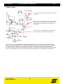
12.7 OCV Control
The OCV is limited to a level of +280 V. When the OCV exceeds the maximum limit, the transistor Q1 is
controlled to conducting state. When the transistor Q1 starts to conduct the optocoupler OC1 turns to non-
conducting state and the transistor Q2 starts to conduct, which regulates the power stage control voltage in
order to limit the O.C.V.
How to measure the OCV?
Warning! High voltage!
1. Disconnect the unit from the mains supply.
2. Disable the HF circuit by removing the connector A5 or A6 from the control board (HF transformer’s
primary winding)!
3. Connect the air supply.
4. Connect a meter across the output terminals.
5. Connect the unit to the mains supply and turn the main switch to position 1.
6. Press the torch switch.
Picture 1.
The OCV +280 V at the output terminals.
High voltage!

1921
Ver 1.0 12/2008 -19-
ESAB, Nordic Region
Service Manual Ori
g
o
TM
Cut36i Plasma Cuttin
g
S
y
stem
V
er 1.0
13. Troubleshooting
Check the problem against the symptoms in the following troubleshooting quide. Start the troubleshooting by
checking that the mains supply, the wear parts of the torch and the air supply are ok. See also the chapter;
7. Common Cutting Problems.
Voltages in the plasma cutting equipment are high enough to cause serious injury or possible death!
If the cause cannot be quickly located, turn the main switch to position 0, remove the covers and perform a
simple visual inspection of all the components and wiring. Check the terminal connections, loose or burned
wiring or components, bulged or leaking capacitors, or any other sign of damage.
Symptom Possible cause Check
Main fuse trips immediately
after the power on or when
the torch switch is pressed.
Short circuit in the power stage.
Check the semiconductors of the
primary circuit. See chapter; 11.
Inverter Board.
Preflow 15 sec. is missing
after ”power on”.
1. The solenoid valve is
defective.
2. The power supply for the
control electronics is missing.
3. The control board is defective.
Check the solenoid valve and its
wiring.
See chapter; 12.1 Power
Supply.
See chapter; 12.2 Preflow 15
sec.
Nothing happens when the
torch switch is activated.
1. The switch or the control wires
are broken in the torch.
2. The control board is defective.
Check the torch switch and its
wiring.
See chapter; 12.4 Start.
The preflow starts, but the
cutting arc does not strike
when the torch switch is
activated.
1. The OCV is missing.
2. The power stage is defective.
3. The HF circuit is defective.
See chapter; How to measure
OCV?
If the OCV is missing, check the
operation of power stage and
the condition of the secondary
diodes on the bottom plate. See
chapters; 11.2 Power Stage and
10.7 Secondary Rectifier.
See chapter; 12.5 HF Control.
The air flow indicator on the
front panel does not turn ”on”
when the torch switch is
activated even though the air
supply is ok.
1. The air flow sensor is
defective.
2. The control board is defective.
See the chapters; 10.4 Air Flow
Switch and 12.6 Air Flow
Sensing.

2021
Ver 1.0 12/2008 -20-
ESAB, Nordic Region
Service Manual Ori
g
o
TM
Cut36i Plasma Cuttin
g
S
y
stem
V
er 1.0
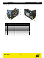
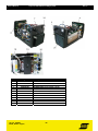
14. Spare Parts
Item Ordering number Description
5 0700156023
HF GENERATOR
8
0558001466 PT-31XL TORCH Assembly
9 0700156008 PRESSURE GAUGE
10 0558008095 FAN
11
0700156010 EMC FILTER
12
0558000410 FLOW SWITCH
13
0558008066 INVERTER PCB
15
0700156013 EARTHCABLEW/CLAMP, L=5m
16
0459172001 PLASTIC FRONT PANEL
17 0558008068 BOTTOM PLATE
22 0700156019 KNOB Dia. 25mm
24
0700156020 SOLENOID VALVE
Page is loading ...
-
 1
1
-
 2
2
-
 3
3
-
 4
4
-
 5
5
-
 6
6
-
 7
7
-
 8
8
-
 9
9
-
 10
10
-
 11
11
-
 12
12
-
 13
13
-
 14
14
-
 15
15
-
 16
16
-
 17
17
-
 18
18
-
 19
19
-
 20
20
-
 21
21


ESAB Origo™Cut 36i User manual
- Category
- Welding System
- Type
- User manual
- This manual is also suitable for
Ask a question and I''ll find the answer in the document
Finding information in a document is now easier with AI
Related papers
-
ESAB Origo™ Cut 36i, Origo™Cut 36i User manual
-
-
ESAB Caddy®Cut User manual
-
ESAB Origo™ Cut 35i User manual
-
-
-
-
-
-

