Page is loading ...

INSTRUCTIONS for
F-15-228
December, 1995
These INSTRUCTIONS are for experienced operators. If you are not fully familiar with the principles of operation
and safe practices for arc welding equipment, we urge you to read our booklet “Precautions and Safe Practices
for Arc Welding, Cutting, and Gouging”, Form 52-529. Do NOT permit untrained persons to install, operate, or
maintain this equipment. Do NOT attempt to install or operate this equipment until you have read and fully
understand these instructions. If you do not fully understand these instructions, contact your supplier for further
information. Be sure to read the Safety Precautions on page 2 before installing or operating this equipment.
PCM-625i
PLASMA ARC CUTTING PACKAGE
This manual provides complete instructions on the PCM-625i Power Source, 230V, 50/60 Hz, P/N 35551.
This manual is also suitable for use with L-TEC PCM-VPi (Series A) and ESAB PCS-43 (Series A) made prior to April, 1995.
Be sure this information reaches the operator.
You can get extra copies through your supplier.

2
USER RESPONSIBILITY
This equipment will perform in conformity with the description thereof contained in this manual and accompanying labels
and/or inserts when installed, operated, maintained and repaired in accordance with the instructions provided. This
equipment must be checked periodically. Defective equipment should not be used. Parts that are broken, missing,
worn, distorted or contaminated should be replaced immediately. Should such repair or replacement become
necessary, the manufacturer recommends that a telephone or written request for service advice be made to the
Authorized Distributor from whom purchased.
This equipment or any of its parts should not be altered without the prior written approval of the manufacturer. The user
of this equipment shall have the sole responsibility for any malfunction which results from improper use, faulty
maintenance, damage, improper repair or alteration by anyone other than the manufacturer or a service facility
designated by the manufacturer.

3
WARNING: These Safety Precautions are for
your protection. They summarize precaution-
ary information from the references listed in
Additional Safety Information section. Before
performing any installation or operating procedures, be
sure to read and follow the safety precautions listed below
as well as all other manuals, material safety data sheets,
labels, etc. Failure to observe Safety Precautions can result
in injury or death.
PROTECT YOURSELF AND OTHERS
--
Some welding, cutting, and gouging pro-
cesses are noisy and require ear pro-
tection. The arc, like the sun, emits ul-
traviolet (UV) and other radiation and
can injure skin and eyes. Hot metal can cause burns.
Training in the proper use of the processes and equip-
ment is essential to prevent accidents. Therefore:
1. Always wear safety glasses with side shields in any work
area, even if welding helmets, face shields, and goggles
are also required.
2. Use a face shield fitted with the correct filter and cover
plates to protect your eyes, face, neck, and ears from
sparks and rays of the arc when operating or observing
operations. Warn bystanders not to watch the arc and not
to expose themselves to the rays of the electric-arc or hot
metal.
3. Wear flameproof gauntlet type gloves, heavy long-sleeve
shirt, cuffless trousers, high-topped shoes, and a weld-
ing helmet or cap for hair protection, to protect against
arc rays and hot sparks or hot metal. A flameproof apron
may also be desirable as protection against radiated
heat and sparks.
4. Hot sparks or metal can lodge in rolled up sleeves,
trouser cuffs, or pockets. Sleeves and collars should be
kept buttoned, and open pockets eliminated from the
front of clothing
5. Protect other personnel from arc rays and hot sparks with
a suitable non-flammable partition or curtains.
6. Use goggles over safety glasses when chipping slag or
grinding. Chipped slag may be hot and can fly far.
Bystanders should also wear goggles over safety glasses.
FIRES AND EXPLOSIONS -- Heat from
flames and arcs can start fires. Hot slag
or sparks can also cause fires and ex-
plosions. Therefore:
1. Remove all combustible materials well away from the
work area or cover the materials with a protective non-
flammable covering. Combustible materials include
wood, cloth, sawdust, liquid and gas fuels, solvents,
paints and coatings, paper, etc.
2. Hot sparks or hot metal can fall through cracks or
crevices in floors or wall openings and cause a hidden
smoldering fire or fires on the floor below. Make certain
that such openings are protected from hot sparks and
metal.“
3. Do not weld, cut or perform other hot work until the
workpiece has been completely cleaned so that there
are no substances on the workpiece which might pro-
duce flammable or toxic vapors. Do not do hot work on
closed containers. They may explode.
4. Have fire extinguishing equipment handy for instant use,
such as a garden hose, water pail, sand bucket, or
portable fire extinguisher. Be sure you are trained in its
use.
SAFETY PRECAUTIONS
10/98
5. Do not use equipment beyond its ratings. For example,
overloaded welding cable can overheat and create a fire
hazard.
6. After completing operations, inspect the work area to
make certain there are no hot sparks or hot metal which
could cause a later fire. Use fire watchers when neces-
sary.
7. For additional information, refer to NFPA Standard 51B,
"Fire Prevention in Use of Cutting and Welding Pro-
cesses", available from the National Fire Protection Asso-
ciation, Batterymarch Park, Quincy, MA 02269.
ELECTRICAL SHOCK -- Contact with live
electrical parts and ground can cause
severe injury or death. DO NOT use AC
welding current in damp areas, if move-
ment is confined, or if there is danger of
falling.
1. Be sure the power source frame (chassis) is connected
to the ground system of the input power.
2. Connect the workpiece to a good electrical ground.
3. Connect the work cable to the workpiece. A poor or
missing connection can expose you or others to a fatal
shock.
4. Use well-maintained equipment. Replace worn or dam-
aged cables.
5. Keep everything dry, including clothing, work area,
cables, torch/electrode holder, and power source.
6. Make sure that all parts of your body are insulated from
work and from ground.
7. Do not stand directly on metal or the earth while working
in tight quarters or a damp area; stand on dry boards or
an insulating platform and wear rubber-soled shoes.
8. Put on dry, hole-free gloves before turning on the power.
9. Turn off the power before removing your gloves.
10. Refer to ANSI/ASC Standard Z49.1 (listed on next page)
for specific grounding recommendations. Do not mis-
take the work lead for a ground cable.
ELECTRIC AND MAGNETIC FIELDS — May
be dangerous. Electric current flowing
through any conductor causes localized
Electric and Magnetic Fields (EMF). Weld-
ing and cutting current creates EMF
around welding cables and welding ma-
chines. Therefore:
1. Welders having pacemakers should consult their physi-
cian before welding. EMF may interfere with some pace-
makers.
2. Exposure to EMF may have other health effects which are
unknown.
3. Welders should use the following procedures to minimize
exposure to EMF:
A. Route the electrode and work cables together. Secure
them with tape when possible.
B. Never coil the torch or work cable around your body.
C. Do not place your body between the torch and work
cables. Route cables on the same side of your body.
D. Connect the work cable to the workpiece as close as
possible to the area being welded.
E. Keep welding power source and cables as far away
from your body as possible.
F15-660

4
FUMES AND GASES -- Fumes and
gases, can cause discomfort or harm,
particularly in confined spaces. Do
not breathe fumes and gases. Shield-
ing gases can cause asphyxiation.
Therefore:
1. Always provide adequate ventilation in the work area by
natural or mechanical means. Do not weld, cut, or gouge
on materials such as galvanized steel, stainless steel,
copper, zinc, lead, beryllium, or cadmium unless posi-
tive mechanical ventilation is provided. Do not breathe
fumes from these materials.
2. Do not operate near degreasing and spraying opera-
tions. The heat or arc rays can react with chlorinated
hydrocarbon vapors to form phosgene, a highly toxic
gas, and other irritant gases.
3. If you develop momentary eye, nose, or throat irritation
while operating, this is an indication that ventilation is not
adequate. Stop work and take necessary steps to im-
prove ventilation in the work area. Do not continue to
operate if physical discomfort persists.
4. Refer to ANSI/ASC Standard Z49.1 (see listing below)
for specific ventilation recommendations.
5. WARNING: This product, when used for welding or
cutting, produces fumes or gases which
contain chemicals known to the State of
California to cause birth defects and, in
some cases, cancer. (California Health &
Safety Code
§25249.5 et seq.)
CYLINDER HANDLING -- Cylinders, if mis-
handled, can rupture and violently re-
lease gas. Sudden rupture of cylinder,
valve, or relief device can injure or kill.
Therefore:
1. Use the proper gas for the process and use the proper
pressure reducing regulator designed to operate from
the compressed gas cylinder. Do not use adaptors.
Maintain hoses and fittings in good condition. Follow
manufacturer's operating instructions for mounting regu-
lator to a compressed gas cylinder.
2. Always secure cylinders in an upright position by chain
or strap to suitable hand trucks, undercarriages, benches,
walls, post, or racks. Never secure cylinders to work
tables or fixtures where they may become part of an
electrical circuit.
3. When not in use, keep cylinder valves closed. Have
valve protection cap in place if regulator is not con-
nected. Secure and move cylinders by using suitable
hand trucks. Avoid rough handling of cylinders.
4. Locate cylinders away from heat, sparks, and flames.
Never strike an arc on a cylinder.
5. For additional information, refer to CGA Standard P-1,
"Precautions for Safe Handling of Compressed Gases in
Cylinders", which is available from Compressed Gas
Association, 1235 Jefferson Davis Highway, Arlington,
VA 22202.
EQUIPMENT MAINTENANCE -- Faulty or im-
properly maintained equipment can cause
injury or death. Therefore:
1. Always have qualified personnel perform the installa-
tion, troubleshooting, and maintenance work. Do not
perform any electrical work unless you are qualified to
perform such work.
2. Before performing any maintenance work inside a power
source, disconnect the power source from the incoming
electrical power.
3. Maintain cables, grounding wire, connections, power
cord, and power supply in safe working order. Do not
operate any equipment in faulty condition.
4. Do not abuse any equipment or accessories. Keep
equipment away from heat sources such as furnaces,
wet conditions such as water puddles, oil or grease,
corrosive atmospheres and inclement weather.
5. Keep all safety devices and cabinet covers in position
and in good repair.
6. Use equipment only for its intended purpose. Do not
modify it in any manner.
ADDITIONAL SAFETY INFORMATION -- For more
information on safe practices for electric arc
welding and cutting equipment, ask your sup-
plier for a copy of "Precautions and Safe
Practices for Arc Welding, Cutting and Goug-
ing", Form 52-529.
The following publications, which are available from the
American Welding Society, 550 N.W. LeJuene Road, Mi-
ami, FL 33126, are recommended to you:
1. ANSI/ASC Z49.1 - "Safety in Welding and Cutting"
2. AWS C5.1 - "Recommended Practices for Plasma Arc
Welding"
3. AWS C5.2 - "Recommended Practices for Plasma Arc
Cutting"
4. AWS C5.3 - "Recommended Practices for Air Carbon Arc
Gouging and Cutting"
5. AWS C5.5 - "Recommended Practices for Gas Tungsten
Arc Welding“
6. AWS C5.6 - "Recommended Practices for Gas Metal Arc
Welding"“
7. AWS SP - "Safe Practices" - Reprint, Welding Handbook.
8. ANSI/AWS F4.1, "Recommended Safe Practices for
Welding and Cutting of Containers That Have Held
Hazardous Substances."
MEANING OF SYMBOLS - As used throughout
this manual: Means Attention! Be Alert! Your
safety is involved.
Means immediate hazards which, if not
avoided, will result in immediate, seri-
ous personal injury or loss of life.
Means potential hazards which could
result in personal injury or loss of life.
Means hazards which could result in
minor personal injury.

5
1.1 GENERAL
The PCM-625i is the perfect power source for duct work,
construction, automotive, painted panels, holes in cabi-
nets, ornamental work,, etc. This unique inverter power
source is loaded with desirable features:
portable - only 46 lbs (21 kg) plastic case
uses shop air
completely variable from 10 amps to 40 amps
comes with “XT” consumables and heavy duty heat
shield
recommended maximum thickness 5/8"
severs up to 3/4"
trigger lock-in
heavy-duty air filter-regulator
air check switch
proven patented PT-31XL torch - 25 feet (7.6 m)
spare parts kit
2 year warranty
40% duty cycle at rated 40 amps output - fan cooled
overload light
power-on light
circuit breaker protection
grate cutting capability
torch connection safety interlock cover
“XT” nozzle easily follows templates
1.2 SPECIFICATIONS
PCM-625i
Input Voltage .......................... 230 V, 60 Hz, 1 Phase
Input Current @ rated load .................. 37 A @ 230 V
Output Rating ...................................... 10 to 40 amps
Duty Cycle @ Rated Output ................................ 40%
Open Circuit Voltage ............................. 200 DC max.
Plasma Gas ..................... Air @ 75psi (180 - 200 cfh)
Dimensions .......................... 8.3" w x 17.3" h x 16.5" l
.......................... (210 mm w x 438 mm h x 420 mm l)
Weight .................................................. 46 lbs (21 kg)
PT-31XL Torch
Current Capacity ...................................... 50 A SPDC
Shipping Wgt. ........................................... 2 lbs (1 kg)
Length of Service Lines ......................... 25-ft. (7.6 m)
Dimensions:
SECTION 1 DESCRIPTION
Note the high open circuit voltage. Use only torches
designed for this equipment. Do NOT attempt to use
this equipment with any process other than plasma
arc cutting.
Do not use any torch with this power source other
than the PT-31XL torch. Serious injury may occur if
used with any other torch.
1.3 EQUIPMENT SUPPLIED
A. PACKAGE AVAILABLE
PCM-625i, 230V, PT-31XL 75° 25' .......... P/N 604473
Package includes:
PCM-625i, 230V,
Inverter Power Source w/cable ................. P/N 35551
PT-31XL 75° Torch w/25-ft. lines ...................... 20080
Torch Spare Parts Kit ................................... 21052
Work Cable, 25-ft............................................ 680560
Air Filter-Regulator ......................................... 21698
Hose Assy., Air 2-ft. ........................................ 680545
Torch Spare Parts Kit (P/N 21052) contains the following PT-31XL
torch parts in a convenient case:
2—Heat Shield, P/N 20282
4—Nozzle (Tip), P/N 21008
3—Electrode, P/N 20862
1—Swirl Baffle, P/N 20463
2—Plunger, P/N 20324
Max. inlet pressure to filter-regulator: 150 psig.
1.4 REQUIRED EQUIPMENT
Air Supply - A source of clean, dry air from a compressor
that supplies at least 75 psig (50 psig with standard
consumables). It should not exceed 150 psig which is the
maximum inlet pressure rating of the air filter-regulator
(20963) supplied with the package.
Fig. 1-1
5 1/4"
(133mm)
75° Torch
2 1/4"
(57mm)

6
SECTION 2 INSTALLATION
2.1 INSTALLATION
Proper installation can contribute materially to satisfac-
tory and trouble-free operation of the cutting package. It
is suggested that each step in this section be studied
carefully and followed as closely as possible.
2.2. INSPECTION AND PLACEMENT
1. Having removed the shipping container inspect for
evidence of concealed damage which may not have
been apparent upon receipt of the power source.
Notify the carrier of any defects or damage at once.
2. Check the container for any loose parts. Check air
louvers on all panels of cabinet and holes through the
base of any packing materials that may obstruct air
flow through the power source.
3. The components in the PCM-625i power source are
maintained at proper operating temperatures by fan
cooling. Air is drawn through louvers on front and side
panels and then out through the rear panel. Locate the
power source in an open area where air can circulate
freely through the openings. Allow at least one foot of
clearance between the power source and wall or any
other obstruction. The area around the power source
should be relatively free of dust, fumes, and excessive
heat.
2.3. PRIMARY INPUT ELECTRICAL CONNECTION
Electric Shock can kill! Precautionary measures
should be taken to provide maximum protection
against electrical shock. Be sure that all power is off
by opening the line (wall) disconnect switch and by
unplugging the power cord to the power source
when connections are made inside the power source.
1. The PCM-625i, 230 V power source is equipped with
a 6-ft., 3-conductor input power cord without plug. The
customer must supply and wire a 230V/30A plug to the
input cable (NEMA plug 6-30P is recommended) for
plugging into a 208 or 230 volt receptacle. Do NOT
connect to 460 volt power. A line (wall) disconnect
switch, with a 50 amp fuse or circuit breaker, should
also be provided at a main power panel. The cable
connecting the disconnect switch to the receptacle
should include three (two power and one ground) No.
10 AWG insulated conductors.
2.4. SECONDARY (OUTPUT) CONNECTIONS
(Refer to Fig. 2-1)
Before making any connections to the power source
output terminals, make sure that all primary input
power to the power source is deenergized (off) at the
main disconnect switch and that input power cable
is unplugged.
1. For operator safety, the torch and work cable connec-
tions are located on the output terminal board at the
front bottom of power source under the safety inter-
lock cover. Remove safety interlock cover.
2. Thread the terminal lug end of the work cable assem-
bly through the right bushing of the safety cover and
connect it to the WORK terminal on the output terminal
board. Connection should be wrench-tight.
3. Thread the power cable and switch lead of the PT-
31XL through the left open bushing of the safety
cover. Connect power cable to the torch fitting (left-
hand threads) and plug in the switch lead to the torch
switch receptacle on the output terminal board. Make
sure the power cable connection is wrench-tight.
Make sure plug of switch lead is firmly locked in place.
4.Reassemble the safety interlock cover to the power
source. The power source will not operate without the
safety interlock cover in place nor should you attempt
to bypass the safety interlock circuitry.
5. If necessary, assemble air control equipment as fol-
lows:
a. Assemble the filter-regulator and mounting bracket
to the power source as shown in Fig. 2.
b. Connect the 24-in. long air hose to the filter-regula-
tor outlet and to fitting on the power source. Note
that the regulator end of hose has left-hand threads
and the other end is right-handed. Make sure hose
connections are tightened firmly with a wrench.
c. Connect your air supply to the inlet connection of
the filter-regulator.
6. Clamp the work cable to the workpiece. Be sure the
workpiece is connected to an approved earth ground
with a properly sized ground cable.
3.1. ADJUSTMENTS & OPERATIONS
Never, under any circumstances, operate the power
source with the cover removed. In addition to the safety
hazard, improper cooling may cause damage to internal

7
SECTION 2 INSTALLATION
DO NOT
REMOVE
POWER SWITCH
CUSTOMER FUSED
LINE DISCONNECT
SWITCH
(50 amp fuse or
circuit breaker)
HOSE ASSY.
(2-FT.) - 680545
AIR SUPPLY
(150 PSIG MAX)
(Customer supplied)
AIR FILTER-REGULATOR -
20963 (Set at 75psig)
NO. 10 CU/AWG
3-COND.
(Customer supplied)
RECEPTACLE
(Customer supplied)
PLUG - 950835
SAFETY INTERLOCK
(OPTICAL SWITCH)
WORK
SAFETY
GROUND
WORK CABLE
(25FT.) - 680560
Allow at least 10-ft.
between work and power source
Fig. 2-1. - PCM-625i Interconnection Diagram

8
SECTION 3 OPERATION
components. Keep side panels closed when power
source is energized. Also make sure you are adequately
protected before you start cutting — protective helmet
and gloves should always be worn. Refer to page 3 for
additional operating precautions.
3.2 TORCH ADJUSTMENTS
Make sure power switch on power source is in OFF
position and primary input power is deenergized.
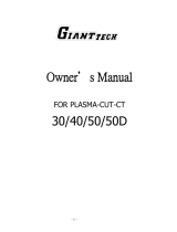
1. Assembling "XT" Consumable Parts - To assemble
"XT" consumables, remove the seat supplied with the
torch. Insert the plunger into the head. (The plunger is
reversible.) Then reassemble the seat firmly with a
wrench. Install the electrode, baffle, nozzle, and heat
shield as shown in Fig. 3-1. Tighten heat shield snugly
but do not overtighten.
BE SURE to install the swirl baffle in the torch.
Failure to do so would allow the nozzle (tip) to
contact the electrode. This contact would permit
high voltage to be applied to the nozzle. Your contact
with the nozzle or workpiece could then result in
serious injury or death by electric shock.
3.3. PCM-625i CONTROLS & ADJUSTMENTS
(See Fig. 3-2)
1. Power Switch (located on rear panel) - When
placed in ON position, green pilot light will glow
indicating control circuit is energized and the cooling
fan will run.
2. Output Current Control - Adjustable from 10 to 40
amps to suit cutting conditions.
3. Air Check Switch - When placed in ON position, air
filter-regulator can be adjusted to desired pressure
(75psig with "XT" consumables) before cutting opera-
tions. Allow air to flow for a few minutes. This should
remove any condensation that may have accumu-
lated during shut down. Be sure to place switch in OFF
position before starting cutting operations.
4. Lock-In Switch - When placed in ON position, per-
mits releasing torch switch button after cutting arc has
been initiated. To extinguish arc at end of cut, press
and release torch switch button again or pull torch
away from work. When placed in OFF position, torch
switch must be held closed by the operator during the
entire cutting operation and then released at the end
of cut.
5. Overload Light - Will glow red under the following
conditions and operations will come to a complete
stop:
a. When duty cycle has been exceeded. The duty
cycle of this power source is 40% at rated output
current of 40 amps. Duty cycle is based on a 10
minute cycle; therefore, the power source can
operate up to 4 minutes and then allowed to cool
down for next 6 minutes.
b. When input voltage is outside the range of 190 to
253 V.
LOCK-IN
SWITCH
AIR CHECK
SWITCH
POWER LIGHT
(GREEN)
OVERLOAD LIGHT
(RED)
POWER SWITCH
(ON REAR PANEL)
Fig. 3-2 - Controls on PCM-625i Power Source
The front end of the torch contains a gas flow check
valve that acts in conjunction with the circuitry pro-
vided in the power source. This patented system
provides a safety interlock preventing the torch from
being accidentally energized with high voltage when
the heat shield is removed and the torch switch is
accidentally closed.
For additional torch information, see booklet (F-14-
246) packed with the PT-31XL torch.
NOTE: Nozzles
Marked By
Amperage
Plunger
20324
19679
Seat
20862
Electrode
Baffle
20463
21008-40AMP
Heat Shield
20282
Fig. 3-1 - Assembly of "XT" Consumable Parts
Nozzle
(Tip)
OUTPUT
CURRENT
CONTROL

9
SECTION 3 OPERATION
3.3 OPERATION
Wear the usual protective gloves, clothing, and hel-
met. Helmet with filter lens shade No. 6 or 7 should
provide adequate protection for your eyes.
Never touch any parts forward of the torch handle
(nozzle, heat shield, electrode, etc.) unless the power
switch is in the OFF position.
CAUTION: Do not depress the torch switch unless the
torch nozzle is touching or within 0.020-in.
(less than 1/32-in.) of the workpiece.
CAUTION: Locate the power source at least 10-ft. from
the cutting work area. Chips and hot slag
from the cutting operation can damage the
power source.
After placing the primary (wall) switch to the ON position
and making control and air pressure adjustments as
described above, proceed as follows:
1. Touch the nozzle (tip) of the torch to the workpiece (or
within 0.020-in. of the workpiece) holding the torch at
about 15- 30° angle to avoid damaging the nozzle
(tip).
2. Depress the torch switch. (Air and high frequency
should energize.)
3. Two seconds after depressing torch switch, the plasma
arc will start cutting. (If using the LOCK-IN mode, torch
switch can be released after establishing the cutting
arc.)
4. After starting the cut, the nozzle can be dragged along
the workpiece if cutting up to 1/4'’ thick material. When
cutting material greater than 1/4'’, maintain a 1/8'’
nozzle (tip)-to-work (standoff) distance.
5. When ending a cut, the torch switch should be re-
leased (press and release if using LOCK-IN mode)
and lifted off the workpiece just before the end of the
cut to minimize double-arcing which can damage the
nozzle (tip). This is to prevent high frequency from
reigniting after cutting arc extinguishes.
CORRECT TOO FAST TOO SLOW
Fig. 3-3 - Effect of Cutting Speed
Cutting Speed Range — PCM-625i
(Using Air with XT Consumables @ 75 psi)
Output Cutting
Thickness Current Speed
Material (In.) (Amps) (ipm)
Carbon 1/16 30 180
Steel 1/8 30 75
(AISI 1020) 1/8 40 100
1/4 40 33
3/8 40 16
1/2 40 10
5/8 40 7
3/4 40 5
Stainless 1/16 30 200
Steel 1/8 30 85
(AISI 304) 1/8 40 100
1/4 40 35
3/8 40 13
1/2 40 8
Aluminum 1/16 30 200
(6061) 1/8 30 85
1/8 40 100
1/4 40 35
3/8 40 13
1/2 40 8
NOTE: The Speeds given here are typical for best quality cuts. Your actual
speeds may vary depending on material composition, surface condi-
tion, operator technique, etc. If cutting speed is too fast, you may lose
the cut. With slower speeds excessive dross may accumulate. If speed
is too slow, the arc may extinguish. Air cutting typically produces a
rough face on stainless steel and aluminum.
6. In the postflow mode, the arc can be restarted imme-
diately by depressing the torch switch. The two sec-
ond preflow will automatically cancel.
3.4 OPERATING TECHNIQUES
1. Piercing - Materials (up to 1/4-in. thick) may be
pierced with the torch touching the work. When pierc-
ing thicker materials (up to 3/16-in. aluminum or 1/4-
in. stainless or carbon steel) immediately raise the
torch to 1/16-in. standoff after initiating the cutting arc.
This will reduce the chance of spatter from entering
the torch and prevent the possibility of welding the
nozzle to the plate. The torch should be angled at
about 30° when starting to pierce, and then straight-
ened after accomplishing the pierce.
2. Grate Cutting - For rapid restarts, such as grate or
heavy mesh cutting, do not release the torch switch.
This avoids the 2 second preflow portion of the cutting
cycle.

10
SECTION 3 OPERATION
SECTION 4 MAINTENANCE
1. Check heat shield on torch. It should be replaced if
damaged.
2. Check the torch electrode and cutting nozzle for wear
on a daily basis.
3. Make sure cable and hoses are not damaged or
kinked.
4. Make sure all plugs, fittings, and ground connections
are tight.
5. With all input power disconnected, and wearing proper
eye and face protection, blow out the inside of the
cutting power source using low-pressure dry com-
pressed air.
CAUTION: Water or oil occasionally accumulates in
compressed air lines. Be sure to direct the
first blast of air away from the equipment to
avoid damage.
6. Check and bleed water or oil from the filter beneath the
air regulator.
4.1 MAINTENANCE
If this equipment does not operate properly, stop
work immediately and investigate the cause of the
malfunction. Maintenance work must be performed
by an experienced person, and electrical work by a
trained electrician. Do not permit untrained persons
to inspect, clean, or repair this equipment. Use only
recommended replacement parts.
4.2. INSPECTION AND CLEANING
Frequent inspection and cleaning of the PCM-625i power
source is recommended. Some suggestions for inspect-
ing and cleaning are as follows:
Make sure the power is shut off.
3.5 COMMON CUTTING FAULTS
Listed below are common cutting problems followed by
probable cause of each. If problems are determined to be
caused by the PCM-625i, see your ESAB representa-
tive.
1. Insufficient Penetration.
a. Cutting speed too fast.
b. Damaged cutting nozzle.
c. Improper air pressure.
2. Main Arc Extinguishes.
a. Cutting speed too slow.
3. Dross Formation. (In some materials and thick-
nesses, it may be impossible to get dross-free
cuts.)
a. Cutting speed too fast or too slow.
b. Improper air pressure.
c. Faulty nozzle or electrode.
4. Double Arcing. (Damaged Nozzle Orifice.)
a. Low air pressure.
b. Damaged cutting nozzle.
c. Loose cutting nozzle.
d. Heavy spatter.
5. Uneven Arc.
a. Damaged cutting nozzle or worn electrode.
6. Unstable Cutting Conditions.
a. Incorrect cutting speed.
b. Loose cable or hose connections.
c. Electrode and/or cutting nozzle in poor condition.
7. Main Arc Does Not Strike.
a. Loose connections.
8. Poor Consumable Life.
a. Improper gas pressure.
b. Contaminated air supply.

11
SECTION 5 TROUBLESHOOTING
The cause of control malfunctions can be found by
referring to the sequence of operations and electrical
schematic diagram and checking out the various compo-
nents. A volt-ohmmeter will be necessary for some of
these checks.
NOTE: Before checking voltages in the circuit, discon-
nect the power from the high frequency genera-
tor to avoid damaging your voltmeter.
Voltages in plasma cutting power source are high
enough to cause serious injury or possibly death. Be
particularly careful around power source when the
covers are removed.
5.1 TROUBLESHOOTING
Be sure that all primary power to the power source
has been externally disconnected. Open wall dis-
connect switch or circuit breaker before attempting
inspection or work inside of the power source.
Check the problem against the symptoms in the following
troubleshooting guide. The remedy may be quite simple.
If the cause cannot be quickly located, shut off the input
power, open up the power source, and perform a simple
visual inspection of all the components and wiring. Check
for secure terminal connections, loose or burned wiring
or components, bulged or leaking capacitors, or any
other sign of damage or discoloration.

12
Depress torch switch. After 2 seconds high freq. should be
seen or heard.
Yes No
2. No Air
Is air adjusted to 75psig?
Yes No Adjust
Yes No Connect
Is air hose connected:
Does air come on with air check switch?
Yes No
Check Continuity of torch switch
À
Power source defective
OK No Defective torch switch
¾
No electrode in torch
Electrode too short
Replace electrode
5.2 TROUBLESHOOTING
1. Difficult Starting
Change electrode
Change Nozzle
Check for clean ground connection
Check air pressure - 75psig for "XT" Nozzles
Check torch power cable for continuity
SECTION 5 TROUBLESHOOTING
Is air check switch OFF?
Yes No Turn switch OFF
Does arc start when nozzle contacts work without depress-
ing torch switch
3. Air does not shut off
Yes No
Check for short in torch switch
Defective Defective
Solenoid Power source
Is main 230 volt switch ON?
Yes No Turn on main
disconnect
Is plug in receptacle?
Yes No Insert plug
in receptacle
Is cooling fan turning?
Yes No
Defective
pilot light
Check voltage at receptacle and input power line.
Yes No Check main fuses
Faulty power switch
on power source
¾
À
4. Green "Power" light not energized.
À
À
¾
¾
¾
À
À
À
À
À
À
À
À
À
¾
¾
À
À
¾
Power Source High Freq.
defective Power Source
defective
À
Yes No
Does air flow even when power source's power switch is
OFF?

13
5. Rec "overload" light ON. (See also Symptom 6 below)
Is output terminal off, loose, or damaged
Yes No
z Overload light will energize of voltage falls below 150 volts for 0.3
seconds or exceeds 270 volts even for an instant. The light will not
turn OFF even when correct voltage is restored. Reset by placing
power source's power switch OFF and then ON again.
6. Red "Overload" light immediately turns ON when the
power switch on power source is ON and torch is OFF.
Is output terminal cover attached correctly?
Does optical switch behind output terminal cover actuate?
Turn off power switch on power source and disconnect
input power cable from receptacle
Fix or replace
cover
Is the power source
overheated?
Duty cycle exceeded
40% @ 40 amps output
À
À
Yes No
Adjust voltage z
Is there excessive current through transistor?
À
Yes
Broken resistor or defective output diode.
Defective control circuit.
Yes No
¾
Attach cover.
Check ground cable
for good electrical ground.
Yes No
Insert plug in receptacle and turn ON Main disconnect
switch
Optical switch defective
Output terminal cover deformed.
Is light still on?
Yes No Off (Normal)
Is input voltage normal (190-253 V)?
Yes No Adjust voltage
Turn power switch on power source OFF and then ON
Normal
OK No Defective power source
Is input voltage below 190 or above 253 volts?
SECTION 5 TROUBLESHOOTING
À
À
À
À
À
¾
À
À
¾
À
¾
À
¾
À
Yes No
"Overload" light turns
off when Power Source
cools down.

14
RELEASE
TORCH SWITCH
PUSH
GAS SOLENOID VALVE
PREFLOW
h
g
g
h
FLOW SWITCH
OVERLOAD PILOT LIGHT
HF CIRCUIT
CUTTING ARC (CURRENT
INVERTER
NOTES:
1. When the torch switch is pushed during postflow period, the
postflow and preflow times are canceled, and the HF is energized
immediately.
2. When the red overload pilot light comes on, cutting operation
should be stopped. The postflow time starts from the moment the
torch switch is released.
OVERLOAD PILOT LIGHT
HF CIRCUIT
INVERTER
CUTTING ARC (CURRENT)
FLOW SWITCH
TORCH SWITCH
PUSH
OPEN
PREFLOW
GAS SOLENOID VALVE
hg
2 SEC
gh
10 sec
Position
10 sec
Position
OPEN
CLOSE
CLOSE
OPEN
ENERGIZE
ENERGIZE
CLOSE
POSTFLOW
OPEN
CLOSE
RELEASE PUSH RELEASE
2 Sec
5.3 SEQUENCE OF OPERATION
1. LOCK-IN "OFF" position
2. LOCK-IN "ON" position
SECTION 5 TROUBLESHOOTING

15
Fig. 5-1 - Schematic Diagram - PCM-625i Power Source, 230 V
SECTION 5 TROUBLESHOOTING

16
6.1 GENERAL
1. Replacement parts are keyed on the illustrations which follow. Order replacement parts by part number and
part name as shown on the illustrations. DO NOT ORDER BY PART NUMBER ALONE.
2. When ordering, be sure to state quantity of each part needed.
3. Always state the series or serial number of the power source on which the parts are to be used. The serial
number is stamped on the power source's nameplate.
4. Indicate any special shipping instructions.
5. Order replacement parts from your ESAB distributor or from ESAB Welding & Cutting Products, Customer
Service Department, Florence, SC.
For replacement parts information on the PT-31XL Torch, refer to Form F-14-246.
31978 -
(PL1) POWER
(PL1) WARNING
31980 -
(S1) AIR CHECK
951895 -
(S2) LOCK IN
31963 -
(V.R1) OUTPUT CURRENT
FRONT PANEL
TERMINAL COVER
PHS (REF.)
OUTPUT TERMINAL (METAL)
OUTPUT TERMINAL (TORCH)
182W64 - (CON 1)
TORCH SWITCH RECEPTACLE
Fig. 6-1 - Front View - PCM-625i Power Source, 230 V
SECTION 6 REPLACEMENT PARTS

17
951897 (MCB)
POWER SWITCH
AIR UNIT
INPUT CABLE
GAS INLET
REAR PANEL
Fig. 6-2 - Rear View - PCM-625i Power Source, 230 V
951911 (PCB2)
H. F. CIRCUIT
32500
(F) FUSE
AIR UNIT
951903 (FAN)
COOLING FAN
31967 (SOL)
SOLENOID VALVE
680566 (FLS)
FLOW SWITCH
951909 (PCB1)
CONTROL CIRCUIT
951912 (PCB3)
GATE CIRCUIT
951894 (CT)
CURRENT
TRANSFORMER
31975 (C2)
CAPACITOR
31981 (CC)
COUPLING COIL
31976 (C3)
CAPACITOR
31006 (SA3)
SURGE ABSORBER
Fig. 6-3 - Left Side View - PCM625i Power Source, 230 V
SECTION 6 REPLACEMENT PARTS

18
Fig. 6-4 - Right Side View - PCM-625i Power Source, 230 V
951894 (CT) CURRENT
TRANSFORMER
31975 (C2)
CAPACITOR
951907 (T2)
AUXILIARY
TRANSFORMER
951602 (THS2)
THERMAL SWITCH
951905 (T1)
MAIN TRANSFORMER
951610 (C8, 9, 10)
CAPACITOR (X3)
30711 (R1)
RESISTOR
951909 (PCB1)
CONTROL CIRCUIT
32500(F) FUSE
951922 (PCB2)
31019 (SA1, 2)
SURGE ABSORBER
951911 (PCB2)
H. F. CIRCUIT
(C1) CAPACITOR
AIR UNIT
951903 (FAN)
COOLING FAN
951603 (THS3)
THERMAL SWITCH
951908 (FCH)
D. C. REACTOR
Fig. 6-5 - Inside Top View - PCM-625i Power Source, 230 V
951597 (R2) RESISTOR
31976 (C3, 4)
CAPACITOR (X2)
951910 (PHS)
PHOTO SWITCH
951907 (T2) AUXILIARY
TRANSFORMER
951894 (CT)
CURRENT TRANSFORMER
951606 (R3, 4) RESISTOR (X2)
951604 (R6)
RESISTOR (X2)
951901 (D1)
DIODE
(FIN) COOLING
FIN
951900 (Q)
TRANSISTOR (1GBT)
951602 (THS1)
THERMAL SWITCH
951902 (D) DIODE
951605 (R5) RESISTOR
951608 (C7) CAPACI-
TOR
SECTION 6 REPLACEMENT PARTS
951898 (C5, 6) CAPACITOR (X2)
31975 (C2) CAPACITOR

19
951909 (PCB1)
CONTROL
CIRCUIT
951911 (PCB2)
H.F. CIRCUIT
Fig. 6-6 - Top View - PCM-625i, 230 V Power Source
SECTION 6 REPLACEMENT PARTS

F-15-228 12/95 3M Printed in U.S.A.
IF YOU DO NOT KNOW WHOM TO CALL
Telephone: (800) ESAB-123/ Fax: (843) 664-4452/ Web:http://www.esab.com
Hours: 7:30 AM to 5:00 PM EST
A. CUSTOMER SERVICE QUESTIONS:
Order Entry Product Availability Pricing Delivery
Order Changes Saleable Goods Returns Shipping Information
Eastern Distribution Center
Telephone: (800)362-7080 / Fax: (800) 634-7548
Central Distribution Center
Telephone: (800)783-5360 / Fax: (800) 783-5362
Western Distribution Center
Telephone: (800) 235-4012/ Fax: (888) 586-4670
B. ENGINEERING SERVICE: Telephone: (843) 664-4416 / Fax : (800) 446-5693
Welding Equipment Troubleshooting Hours: 7:30 AM to 5:00 PM EST
Warranty Returns Authorized Repair Stations
C. TECHNICAL SERVICE: Telephone: (800) ESAB-123/ Fax: (843) 664-4452
Part Numbers Technical Applications Hours: 8:00 AM to 5:00 PM EST
Performance Features Technical Specifications Equipment Recommendations
D. LITERATURE REQUESTS: Telephone: (843) 664-5562 / Fax: (843) 664-5548
Hours: 7:30 AM to 4:00 PM EST
E. WELDING EQUIPMENT REPAIRS: Telephone: (843) 664-4487 / Fax: (843) 664-5557
Repair Estimates Repair Status Hours: 7:30 AM to 3:30 PM EST
F. WELDING EQUIPMENT TRAINING:
Telephone: (843)664-4428 / Fax: (843) 679-5864
Training School Information and Registrations Hours: 7:30 AM to 4:00 PM EST
G. WELDING PROCESS ASSISTANCE:
Telephone: (800) ESAB-123 Hours: 7:30 AM to 4:00 PM EST
H. TECHNICAL ASST. CONSUMABLES:
Telephone : (800) 933-7070 Hours: 7:30 AM to 5:00 PM EST
ESAB Welding & Cutting Products, Florence, SC Welding Equipment
COMMUNICATION GUIDE - CUSTOMER SERVICES
/