ESAB PowerCut 1600 User manual
- Category
- Welding System
- Type
- User manual

Service Manual
Manual # 0558008016- Rev. 1 3/2009
This manual provides service / troubleshooting
instructions for PC1600 consoles beginning with
Serial Number .........PCJ912015
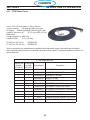
Powercut 1600
Plasmarc Cutting Package
PART NO DESCRIPTION
0558007230 PC1600 230/460V Console
0558007230F PC1600 230/460V BL Console
0558007237 PC1600 575V BL Console
0558007636 PC1600 400V Console
0558007234 PC1600 400V CE Console
0558007883 PC1600 MECH 230/460V
0558007884 PC1600 MECH 400V CE
0558008323 PC1600 460V Console
(BL = Bilingual)
USING THIS MANUAL
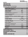
TABLE OF CONTENTS
SAFETY
SPECIFICATIONS
INTRODUCTION
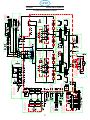
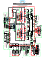
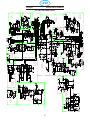
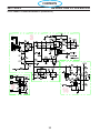
MAIN SCHEMATIC
REPLACEMENT PARTS
WIRING DIAGRAMS
GENERAL
REMOVAL/
REPLACEMENT
PROCEEDURES
MECHANIZED
CONVERSI ON

This equipment will perform in conformity with the description thereof contained in this manual and ac-
companying labels and/or inserts when installed, operated, maintained and repaired in accordance with
the instructions provided. This equipment must be checked periodically. Malfunctioning or poorly main-
tained equipment should not be used. Parts that are broken, missing, worn, distorted or contaminated
should be replaced immediately. Should such repair or replacement become necessary, the manu-
facturer recommends that a telephone or written request for service advice be made to the Authorized
Distributor from whom it was purchased.
This equipment or any of its parts should not be altered without the prior written approval of the manu-
facturer. The user of this equipment shall have the sole responsibility for any malfunction which results
from improper use, faulty maintenance, damage, improper repair or alteration by anyone other than the
manufacturer or a service facility designated by the manufacturer.
This Service Manual is for experienced technicians. If you are not fully familiar with
the principles of operation and safe practices for arc welding and cutting equipment,
we urge you to read our booklet, “Precautions and Safe Practices for Arc Welding,
Cutting, and Gouging,” Form 52-529. Do NOT permit untrained persons to install,
operate, or maintain this equipment. Do NOT attempt to install or operate this equip-
ment until you have read and fully understand these instructions. If you do not fully
understand these instructions, contact your supplier for further information. Be
sure to read the Safety Precautions before installing or operating this equipment.
USER RESPONSIBILITY
2

SECTIONS
1
3
2
4.0
4
4.4
4.5
4.9
4.6
4.11
4.10
4.8
4.7
4.1
4.3
4.2
4.12
4.13
4.14
4.15
4.16
4.17
4.18
4.19
5
7
6
8
10
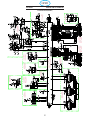
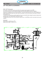
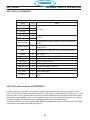
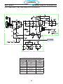
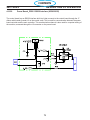
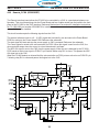
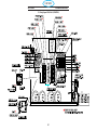
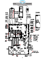
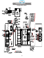
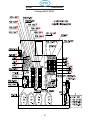
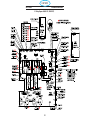
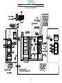
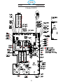
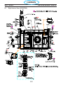
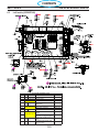
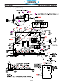
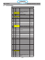
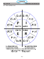
SCHEMATIC SECTION MAP
CONTROL TRANSFORMER T2
INPUT BRIDGE BR1
MAIN POWER SWITCH S1
OUTPUT DIODES
VOLTAGE SELECTOR SWITCH SW2
EMC FILTER (CE UNITS) PCB7
PRESSURE TRANSDUCER PT1
HELP CODES
PILOT ARC CIRCUIT
TORCH PT38
PLASMA CONTROL / DISPLAY BOARD PCB1
POWER BOARD PCB2
THERMAL SWITCH TS1
POWER DRIVER PCB3 - PCB4
MAIN TRANSFORMER T1
FILTERS L1-L2
REMOTE PCB6
CONTACTOR K1
SPECIFICATIONS
DESCRIPTION OF OPERATION
INTRODUCTION
SAFETY
SOLENOID SOL1
WIRING DIAGRAMS
MECHANIZED CONVERSION
REPLACEMENT PARTS
ERRORS
GENERAL INFORMATION
3

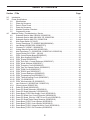
TABLE OF CONTENTS
2.0 Introduction .................................................................12
3.0 PowerSpecications .........................................................13
3.0 Specications ..........................................................13
3.1 Power Up Sequence .....................................................14
3.2 Parts In Place Check.....................................................14
3.3 Power Up Sequence .....................................................14
3.4 Machine Operation Flowchart ..............................................15
3.5 Component Locator......................................................16
4.0 Machine Testing / Troubleshooting / Service .......................................17
4.0 Schematic Section Map 230/460V- 0558007542 ...............................17
4.0 Schematic Section Map 400V/400V CE- 0558007546 ...........................18
4.0 Schematic Section Map 575V- 0558007544...................................19
4.1 Main Power Switch S1 (36107) .............................................20
4.2 Control Transformer T2 (0558007188/0558008546) ............................21
4.3 Input Bridge (0558007068 / 0558007077)) ....................................26
4.4 Contactor K1 (950247 / 0558002576) .......................................28
4.5 Voltage Selector Switch SW2 (0558007183)...................................29
4.6 Main Transformer T1 (0558007189 / 0558007190 / 0558007191) ..................30
4.7 Output Diodes D101, D102 – (951185) .......................................32
4.8 PCB1 Control/Display Board (0558038317) ...................................33
4.8.1 PCB1_Bias Supplies (0558038317) .........................................35
4.8.2 PCB1_Display (0558038317) ..............................................36
4.8.3 PCB1_Error Amp / Current Reference (0558038317)............................37
4.8.4 PCB1_Mode Switches (0558038317) ........................................38
4.8.5 PCB1_Protection Circuit (0558038317).......................................39
4.8.6 PCB1_Gas Test Operate Switch (0558038317) ................................40
4.8.7 PCB1_PWM Circuit (0558038317) ..........................................41
4.8.8 PCB1_RS232 Input (0558038317) ..........................................42
4.8.9 PCB1_Current Reference (0558038317) .....................................43
4.8.10 PCB1_Programming Port(0558038317) ......................................44
4.8.11 PCB1_Thermal Sensing Circuit (0558038317) .................................44
4.8.12 PCB1_I/O (0558038317) ..................................................46
4.8.13 PCB1_Microcontroller U5 (0558038317)......................................46
4.9 Input Inductor L1 (0558007149/ / 0558007151) .................................50
4.9.1 Output Inductor (0558007152)..............................................51
4.10 Power PC Board (0558038315) ............................................52
4.10.1 Power PC Board Schematic (0558038315)....................................53
4.10.2 Power PC Board Schematic 2 (0558038315) ..................................54
4.10.3 Power Board_PCB2 Bias Supply Circuit (0558038315)..........................55
4.10.4 Power PC Board Over Current Protection (0558038315) .........................57
4.10.5 Power PC Board_Pilot Arc / IGBT Driver Circuit (0558038315) ....................58
4.10.6 Power PC Board Single Phase Detection (0558038315) .........................59
4.10.7 Power Board_PCB2 Control Relays (0558038315) .............................60
4.10.7 Power Board_PCB2 Control Relays (0558038315) .............................61
4.10.8 Power Board_PCB2 Voltage Selection Circuit (0558038315) .....................62
4.10.9 Power Board_PCB2 CNC Interface (0558038315) .............................64
Section / Title Page
4

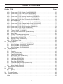
TABLE OF CONTENTS
4.10.10 Power Board_PCB2 Output Circuit (0558038315)..............................65
4.10.11 Power Board_PCB2 V-Arc Circuit (0558038315)...............................66
4.10.12 Power Board_PCB2 Inrush Circuit (0558038315) ..............................67
4.10.13 Power Board_PCB2 Pressure Transducer (0558038315).........................68
4.10.14 Power Board_PCB2 Relay Boost Circuit (0558038315) .........................69
4.10.15 Power Board_PCB2 Torch Trigger Circuit (0558038315).........................70
4.10.16 Buss Supply/IGBT .......................................................71
4.10.17 Power Board_PCB2 Microcontroller Circuit (0558038315) .......................76
4.10.18 Power Board_PCB2 Thermal Switch Circuit (0558038315).......................77
4.10.19 Power Board_PCB2 Gate Driver Circuit (0558038315) ..........................78
4.10.20 Power Board_PCB2 RS232 Interface (0558038315)............................79
4.10.21 Power Board_PCB2 Layout (0558038315) ...................................80
4.11 Power Driver _ PCB3 / PCB4 (0558038335) ..................................84
4.12 Thermal Switch TS1 (951085) ..............................................87
4.13 Pilot Arc Driver Board PCB5 (05580038344) ..................................89
4.14 Help Codes ............................................................91
4.15 Pressure Transducer (0558006148) .........................................92
4.16 EMC Filter 50A _ PCB7 ( CE Units _ 0455803880).............................94
4.17 Solenoid SOL1 (0558007072) ..............................................95
4.18 Remote_PCB6 (0558038337) .............................................96
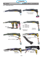
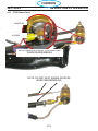
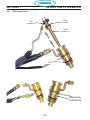
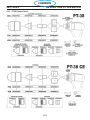
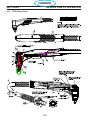
4.19 PT38 Plasma Torch......................................................99
5.0 Wiring Diagrams ............................................................106
5.1 Wiring Diagram 230/460 Volt (0558007543) .................................106
5.2 Wiring Diagram 400/400V CE (0558007547).................................109
5.3 Wiring Diagram 575V (0558007545)........................................ 112
5.3 Wiring Diagram 575V (0558007545)........................................114
6.0 Replacement Parts ..........................................................116
6.1 General . . . . . . . . . . . . . . . . . . . . . . . . . . . . . . . . . . . . . . . . . . . . . . . . . . . . . . . . . . . . . . 116
6.2 Ordering .............................................................116
6.3 Front (0558007540) ....................................................120
6.3 Fan Kit (0558008454) ..................................................120
6.3 Right Interior View (0558007540) ..........................................122
6.3 Top (0558007540) ......................................................124
6.3 Left Inside (0558007540) ................................................126
6.3 Left Inside2 (0558007540) ...............................................128
6.3 Rear View (0558007540) ................................................130
6.3 Front/Rear Isometric Views (0558007540) ...................................132
6.4 ModelSpecicPartsBOM ...............................................134
6.4 ModelSpecicPartsBOM ...............................................136
7.0 MECHANIZED CONVERSION.................................................137
8.0 ERRORS .................................................................145
8.0 Error 13 . . . . . . . . . . . . . . . . . . . . . . . . . . . . . . . . . . . . . . . . . . . . . . . . . . . . . . . . . . . . . . 145
8.1 Error 15 ..............................................................147
9.0 Program Changes...........................................................148
10.0 General Information .........................................................149
Index ....................................................................166
Section / Title Page
5

SECTION 1 SAFETY PRECAUTIONS
WARNING: These Safety Precautions
are for your protection. They summarize
precautionary information from the refer-
ences listed in Additional Safety Informa-
tion section. Before performing any instal-
lation or operating procedures, be sure to
read and follow the safety precautions listed below
as well as all other manuals, material safety data
sheets, labels, etc. Failure to observe Safety Pre-
cautions can result in injury or death.
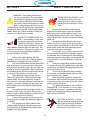
PROTECT YOURSELF AND OTH-
ERS -- Some welding, cutting, and
gouging processes are noisy and
require ear protection. The arc, like
the sun, emits ultraviolet (UV) and
other radiation and can injure skin and eyes. Hot
metal can cause burns. Training in the proper use
of the processes and equipment is essential to
prevent accidents. Therefore:
1. Always wear safety glasses with side
shields in any work area, even if welding helmets,
face shields, and goggles are also required.
2. Use a face shield fitted with the correct filter
and cover plates to protect your eyes, face, neck,
and ears from sparks and rays of the arc when op-
erating or observing operations. Warn bystanders
not to watch the arc and not to expose themselves
to the rays of the electric-arc or hot metal.
3. Wear flameproof gauntlet type gloves,
heavy long-sleeve shirt, cuffless trousers, high-
topped shoes, and a welding helmet or cap for
hair protection, to protect against arc rays and hot
sparks or hot metal. A flameproof apron may also
be desirable as protection against radiated heat
and sparks.
4. Hot sparks or metal can lodge in rolled up
sleeves, trouser cuffs, or pockets. Sleeves and
collars should be kept buttoned, and open pockets
eliminated from the front of clothing.
5. Protect other personnel from arc rays and
hot sparks with a suitable non-flammable partition
or curtains.
6. Use goggles over safety glasses when
chipping slag or grinding. Chipped slag may be
hot and can fly far. Bystanders should also wear
goggles over safety glasses.
FIRES AND EXPLOSIONS -- Heat
from flames and arcs can start
fires. Hot slag or sparks can also
cause fires and explosions. There-
fore:
1. Remove all combustible materials well
away from the work area or cover the materials
with a protective non-flammable covering. Com-
bustible materials include wood, cloth, sawdust,
liquid and gas fuels, solvents, paints and coatings,
paper, etc.
2. Hot sparks or hot metal can fall through
cracks or crevices in floors or wall openings and
cause a hidden smoldering fire or fires on the floor
below. Make certain that such openings are pro-
tected from hot sparks and metal.“
3. Do not weld, cut or perform other hot work
until the workpiece has been completely cleaned
so that there are no substances on the workpiece
which might produce flammable or toxic vapors. Do
not do hot work on closed containers. They may
explode.
4. Have fire extinguishing equipment handy
for instant use, such as a garden hose, water pail,
sand bucket, or portable fire extinguisher. Be sure
you are trained in its use.
5. Do not use equipment beyond its ratings.
For example, overloaded welding cable can over-
heat and create a fire hazard.
6. After completing operations, inspect the
work area to make certain there are no hot sparks
or hot metal which could cause a later fire. Use fire
watchers when necessary.
7. For additional information, refer to NFPA
Standard 51B, “Fire Prevention in Use of Cutting
and Welding Processes”, available from the Na-
tional Fire Protection Association, Batterymarch
Park, Quincy, MA 02269.
ELECTRICAL SHOCK -- Contact
with live electrical parts and ground
can cause severe injury or death.
DO NOT use AC welding current in
damp areas, if movement is con-
6
CONTENTS

SECTION 1 SAFETY PRECAUTIONS
fined, or if there is danger of falling.
1. Be sure the power source frame (chassis)
is connected to the ground system of the input
power.
2. Connect the workpiece to a good
electrical ground.
3. Connect the work cable to the work-
piece. A poor or missing connection can expose
you or others to a fatal shock.
4. Use well-maintained equipment.
Replace worn or damaged cables.
5. Keep everything dry, including cloth-
ing, work area, cables, torch/Piston, and power
source.
6. Make sure that all parts of your body
are insulated from work and from ground.
7. Do not stand directly on metal or
the earth while working in tight quarters or a damp
area; stand on dry boards or an insulating platform
and wear rubber-soled shoes.
8. Put on dry, hole-free gloves before
turning on the power.
9. Turn off the power before removing
your gloves.
10. Refer to ANSI/ASC Standard Z49.1
(listed on next page) for specific grounding recom-
mendations. Do not mistake the work lead for a
ground cable.
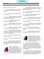
ELECTRIC AND MAGNETIC
FIELDS — May be dangerous. Elec-
tric current flowing through any con-
ductor causes localized Electric and
Magnetic Fields (EMF). Welding and
cutting current creates EMF around
welding cables and welding machines. Therefore:
1. Welders having pacemakers should consult
their physician before welding. EMF may interfere
with some pacemakers.
2. Exposure to EMF may have other health
effects which are unknown.
3. Welders should use the following proce-
dures to minimize exposure to EMF:
A. Route the electrode and work cables
together. Secure them with tape when possible.
B. Never coil the torch or work cable
around your body.
C. Do not place your body between the
torch and work cables. Route cables on the same
side of your body.
D. Connect the work cable to the
workpiece as close as possible to the area being
welded.
E. Keep welding power source and
cables as far away from your body as possible.
FUMES AND GASES -- Fumes
and gases, can cause discomfort
or harm, particularly in confined
spaces. Do not breathe fumes and
gases. Shielding gases can cause
asphyxiation. Therefore:
1. Always provide adequate ventilation in
the work area by natural or mechanical means.
Do not weld, cut, or gouge on materials such as
galvanized steel, stainless steel, copper, zinc, lead,
beryllium, or cadmium unless positive mechanical
ventilation is provided. Do not breathe fumes from
these materials.
2. Do not operate near degreasing and spray-
ing operations. The heat or arc rays can react with
chlorinated hydrocarbon vapors to form phosgene,
a highly toxic gas, and other irritant gases.
7
CONTENTS

Standard P-1, “Precautions for Safe Handling of
Compressed Gases in Cylinders”, which is avail-
able from Compressed Gas Association, 1235 Jef-
ferson Davis Highway, Arlington, VA 22202.
EQUIPMENT MAINTENANCE -- Faulty
or improperly maintained equipment can
cause injury or death. Therefore:
1. Always have qualified personnel perform
the installation, troubleshooting, and maintenance
work. Do not perform any electrical work unless
you are qualified to perform such work.
2. Before performing any maintenance work
inside a power source, disconnect the power
source from the incoming electrical power.
3. Maintain cables, grounding wire, connec-
tions, power cord, and power supply in safe work-
ing order. Do not operate any equipment in faulty
condition.
4. Do not abuse any equipment or acces-
sories. Keep equipment away from heat sources
such as furnaces, wet conditions such as water
puddles, oil or grease, corrosive atmospheres and
inclement weather.
5. Keep all safety devices and cabinet covers
in position and in good repair.
6. Use equipment only for its intended pur-
pose. Do not modify it in any manner.
3. If you develop momentary eye, nose, or
throat irritation while operating, this is an indication
that ventilation is not adequate. Stop work and take
necessary steps to improve ventilation in the work
area. Do not continue to operate if physical dis-
comfort persists.
4. Refer to ANSI/ASC Standard Z49.1 (see
listing below) for specific ventilation recommenda-
tions.
5. WARNING: This product, when used for
welding or cutting, produces fumes or gases which
contain chemicals known to the State of California
to cause birth defects and, in some cases, cancer.
(California Health & Safety Code §25249.5 et seq.)
CYLINDER HANDLING -- Cylinders,
if mishandled, can rupture and vio-
lently release gas. Sudden rupture
of cylinder, valve, or relief device can
injure or kill. Therefore:
1. Use the proper gas for the process and use
the proper pressure reducing regulator designed to
operate from the compressed gas cylinder. Do not
use adaptors. Maintain hoses and fittings in good
condition. Follow manufacturer’s operating instruc-
tions for mounting regulator to a compressed gas
cylinder.
2. Always secure cylinders in an upright posi-
tion by chain or strap to suitable hand trucks, un-
dercarriages, benches, walls, post, or racks. Never
secure cylinders to work tables or fixtures where
they may become part of an electrical circuit.
3. When not in use, keep cylinder valves
closed. Have valve protection cap in place if regu-
lator is not connected. Secure and move cylinders
by using suitable hand trucks. Avoid rough han-
dling of cylinders.
4. Locate cylinders away from heat, sparks,
and flames. Never strike an arc on a cylinder.
5. For additional information, refer to CGA
SECTION 1 SAFETY PRECAUTIONS
8
CONTENTS

ADDITIONAL SAFETY INFORMATION -- For more information on safe practices for electric arc
welding and cutting equipment, ask your supplier for a copy of “Precautions and Safe Practices for
Arc Welding, Cutting and Gouging”, Form 52-529.
The following publications, which are available from the American Welding Society, 550 N.W. LeJuene
Road, Miami, FL 33126, are recommended to you:
1. ANSI/ASC Z49.1 - “Safety in Welding and Cutting”
2. AWS C5.1 - “Recommended Practices for Plasma Arc Welding”
3. AWS C5.2 - “Recommended Practices for Plasma Arc Cutting”
4. AWS C5.3 - “Recommended Practices for Air Carbon Arc Gouging and Cutting”
5. AWS C5.5 - “Recommended Practices for Gas Tungsten Arc Welding“
6. AWS C5.6 - “Recommended Practices for Gas Metal Arc Welding”“
7. AWS SP - “Safe Practices” - Reprint, Welding Handbook.
8. ANSI/AWS F4.1, “Recommended Safe Practices for Welding and Cutting of Containers That Have
Held Hazardous Substances.”
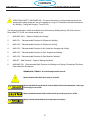
MEANING OF SYMBOLS - As used throughout this manual:
Means Attention! Be Alert! Your safety is involved.
Means immediate hazards which, if not avoided, will result in immediate, serious per-
sonal injury or loss of life.
Means potential hazards which could result in personal injury or loss of life.
Means hazards which could result in minor personal injury.
SECTION 1 SAFETY PRECAUTIONS
9
CONTENTS

SECTION 1 SAFETY PRECAUTIONS
Engineering control must be used to reduce exposures to safe levels (in compliance
with the new PEL). The specific details of the standard are complex and may require
the assistance of an occupational health professional to reach full compliance
For additional information about Hexavalent Chromium contact your occupational health professional
and read the OSHA web page at http://www.osha.gov/SLTC/hexavalentchromium/
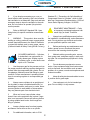
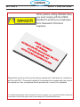
When plasma cutting stainless steel,
you must comply with the OSHA
standard to protect your employees
from Hexavalent Chromium
exposure.
10
CONTENTS

SECTION 1 SAFETY PRECAUTIONS
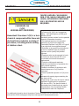
CANCER HAZARD; CAN DAMAGE
SKIN, EYES, NASAL PASSAGES, AND
LUNGS; AUTHORIZED PERSONNEL
ONLY; RESPIRATORS MAY BE
REQUIRED.
For additional information about Hexavalent Chromium contact your occupational health professional
and read the OSHA web page at http://www.osha.gov/SLTC/hexavalentchromium/
CHROMIUM (VI)
Cr(VI)
HEXAVALENT CHROMIUM)
Hexavalent Chromium Cr(VI) is a toxic
chemical component within fume and
dust particles created in a variety of
processes, including plasma cutting
of stainless steel.
On February 28, 2006, the Occupational
Safety and Health Agency (OSHA) pub-
lished a revised
standard to protect workers from the potential
hazards of hexavalent chromium.
• Occupational exposure to hexavalent
chromium (Cr(VI)) must be below the
Permissible Exposure Limit (PEL) of 5 μg/m3
for an eight hour time weighted average.
• Workplace or job-specific monitoring must
be done to establish areas of potential
exposure and to quantify the potential
exposure.
• Employees who may be exposed to levels
of Cr(VI) at or above the new PEL must
be informed and corrective measures
implemented.
• Protective clothing and respiratory
protection must be given to employees who
have potential exposure.
• Medical surveillance of employees with
potential exposure to Cr(VI) must be
conducted.
• Areas of potential exposure to Cr(VI) must
be
indicated with warning signs containing the
text shown at left.
• Engineering control must be used to reduce
exposures to safe levels (in compliance
with the new PEL). The specific details of
the standard are complex and may require
the assistance of an occupational health
professional to reach full compliance
11
CONTENTS

SECTION 2 INTRODUCTION
2.0 INTRODUCTION
2.0 Introduction
2.1 General
The Powercut 1600 is a compact plasma cutting system. As shipped, the system is fully assembled and
ready to cut after being connected to input power and a source of compressed air (350 cfh @ 90 psi / 6.2
bar). The Powercut package uses the heavy-duty PT-38 (manual plasma) torch to deliver cutting power for
selected materials up to 1.50 inch (38.1 mm) thick and severing selected materials up to 1.75 inch (45 mm)
thick
2.2 Scope
Thepurposeofthismanualistoprovidequaliedrepairpersonnelwithtechnicalinformationwhichwillas-
sist in troubleshooting and repairing malfunctions.
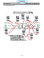
2.3 Service Manual Format
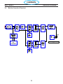
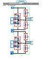
The“machineoperation”owdiagramstartsthebreakdownofthefunctionallyofthePC-1600.Eachofthe
major components is divided into sections, which are described in the pages that follow. Each section in the
owcharthasamatchingsectiononthemainschematicandisappliedtothedescriptionpages.
Each section starts with the schematic view with description, if the section includes a printed circuit PC
board, it is followed by a PC board schematic, the layout of the board and then the component list for the
board. Some PC boards will also have “mini descriptions” of selected circuits. This information is for trou-
bleshooting purposes only, PC board repair is not recommended.
12
CONTENTS

SECTION 3 SPECIFICATIONS
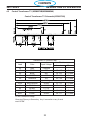
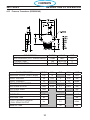
3.0 POWER SPECIFICATIONS
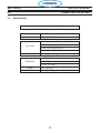
Specications: PowerCut -1600
Cuts 1-1/2 in. (38 mm); severs 1-3/4 in. (45 mm)
1 ph. Input 208/230 vac, 1 ph, 50/60 Hz, 82/74 A
1 ph. Output 90 amps @ 40% duty cycle
3 ph. Input
208/230 vac, 3 ph, 50/60 Hz, 44/40 A
230/460 vac, 3 ph, 50/60 Hz, 40/27 A
400 vac, 3ph, 50/60 Hz, 26 A
575 vac, 3ph, 50/60 Hz, 18 A
3 ph. Output 90 amps @ 60% duty cycle
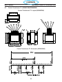
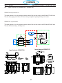
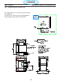
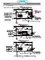
Dimensions
W = 10.5” (267 mm)
H = 15.0” (381 mm)
D = 28.0” (711 mm)
Weight 90 lbs. (40.8 kg)
Air Requirements 350 cfh @ 80 psig (165 l/min @ 5.5 bars)
3.0 Specications
13
CONTENTS

SECTION 3 SPECIFICATIONS
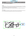
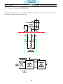
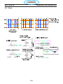
3.1 Power Up Sequence
Power up Sequence of Events
When the machine is turned on, a self diagnostic test is performed to determine the condition of the torch.
Sequence of events
The operator turns on the power switch
The Power Board PCB-1 determines if the input voltage is correct and connects input power.
The Control Board PCB-1 enables the In-rush circuit.
Power Board Relay K1 closes and pre-charges the buss supply.
The machine performs a Parts-in-Place check (PIP) and displays this on the front panel display. (See PIP
test, below)
If the PIP test passes the machine is ready for operation.
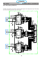
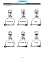
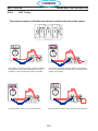
3.2 Parts In Place Check
When the operator closes the torch switch the following occurs:
The Torch Trigger circuit is engaged
Power Board relay RL3, the Mains Contactor Relay, closes.
The Mains Contactor Closes
Power board Relay RL1, the gas solenoid relay, closes.
The gas valve opens
Full buss voltage is available
2secondsofpreow
The piston in the torch cycles
The Control Board PCB-1 turns on the gating pulses
OCV is available
Control board PCB-1 enables the PA relay signal
The Pilot Arc IGBT passes the Pilot Arc current
PilotArcres
Main Arc is established
Pilot Arc is disabled ***
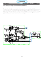
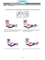
Parts-In-Place
The PC1600 performs a Parts In Place (PIP) check during initial power-up. The following steps are pre-
formed automatically each time power is applied:
Check For Air Pressure (1) Error 5 invoked if No pressure)
Open the gas valve2)
Close the Pilot Arc circuit3)
Pulse on the PWM - the unit looks for an open condition, an open electrode to nozzle. E4) rror 20 is
invoked if there is current ow.
Turns Off the Gas Valve5)
Pulses on the PWM again. 6)
LooksforaShortbetweenelectrodeandnozzle,(looksforcurrentow)7) Error 21 is invoked if
there is no current ow.
3.3 Power Up Sequence
14
CONTENTS


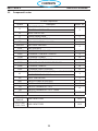
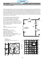
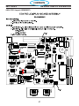
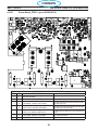
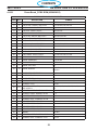
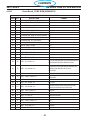
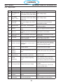
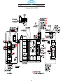
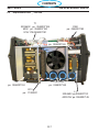
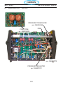
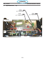
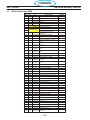
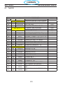
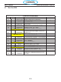
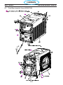
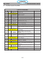
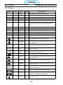
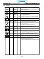
3.5 Component Locator
SECTION 3 SPECIFICATIONS
C37, C40,
C44,C47,
BUSS CAPACITORS 10.16
C101, C102,
C103, C104
BUSS CAPACITORS 10.16
PC1600 Components
Symbol Description Section # 4.
L1
INDUCTOR INPUT
9 REACTOR LINE 3 PHASE
L2 INDUCTOR OUTPUT
T1 TRANSFORMER MAIN 6
T2 TRANSFORMER CONTROL 2
BR1 BRIDGE RECTIFIER 110A 1600V 3
Q101,102 IGBT DUAL 150A 600V
5
Q103 IGBT 50A 1200V
D101,102 DIODE MODULE 100A 600V 7
PCB1 PC BOARD - CONTROL / DISPLAY 8
PCB2 PC BOARD - POWER 10
PCB3,4 PC BOARD - DRIVER BOARD 11
PCB5 PC BOARD - PILOT ARC DRIVER BOARD 13
PCB6 PC BOARD - REMOTE 18
PCB7 PC BOARD - EMC FILTER 50A 16
K1
RELAY SPST 24VAC 20A(110VDC) w/ MAG BLOWOUT
4
CONTACTOR 3P 40A 24VAC
M1 FAN 6” 230CFM 230V 2
SW1 SWITCH POWER 3P 60A 600V 1
SW2 SWITCH VOLTAGE SELECTOR 5
TS1 SWITCH THERMAL N/C 176°F
12
TS2 SWITCH THERMAL N/C 176°F - Solder
SOL1 SOLENOID 17
16
CONTENTS


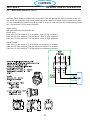
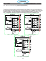
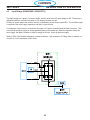
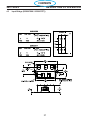
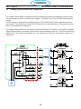
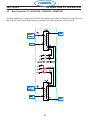
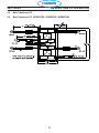
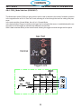
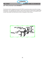
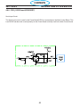
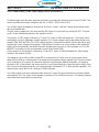
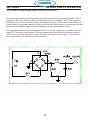
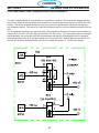
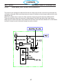
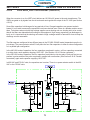
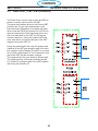
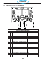
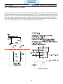
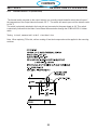
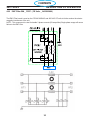
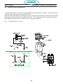
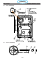
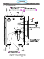
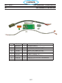
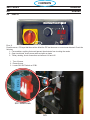
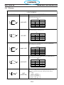
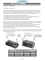
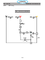
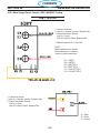
4.1 Main Power Switch S1 (36107)
The main Power Switch is located on the front panel of the unit and passes main input power to the unit.
The switch is a triple pole, single throw, rotary type switch, rated for 63 amps of input current at 690 VAC.
T6 current transformer, located on the B leg of the S1 output is used to monitor for a single phasing condi-
tion. See section 4.10.6 for more information.
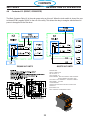
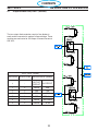
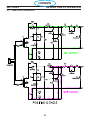
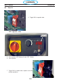
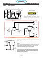
Switch testing:
With power disconnected from the unit:
Switch open:
From pole L1 of the switch to T1 of the switch - open Or High resistance
From pole L2 of the switch to T2 of the switch - open Or High resistance
From pole L3 of the switch to T3 of the switch - open Or High resistance
Switch Closed:
From pole L1 of the switch to T1 of the switch low resistance or shorted
From pole L2 of the switch to T2 of the switch low resistance or shorted
From pole L3 of the switch to T3 of the switch low resistance or shorted
SECTION 4 DESCRIPTION OF OPERATION
20
CONTENTS
Page is loading ...
Page is loading ...
Page is loading ...
Page is loading ...
Page is loading ...
Page is loading ...
Page is loading ...
Page is loading ...
Page is loading ...
Page is loading ...
Page is loading ...
Page is loading ...
Page is loading ...
Page is loading ...
Page is loading ...
Page is loading ...
Page is loading ...
Page is loading ...
Page is loading ...
Page is loading ...
Page is loading ...
Page is loading ...
Page is loading ...
Page is loading ...
Page is loading ...
Page is loading ...
Page is loading ...
Page is loading ...
Page is loading ...
Page is loading ...
Page is loading ...
Page is loading ...
Page is loading ...
Page is loading ...
Page is loading ...
Page is loading ...
Page is loading ...
Page is loading ...
Page is loading ...
Page is loading ...
Page is loading ...
Page is loading ...
Page is loading ...
Page is loading ...
Page is loading ...
Page is loading ...
Page is loading ...
Page is loading ...
Page is loading ...
Page is loading ...
Page is loading ...
Page is loading ...
Page is loading ...
Page is loading ...
Page is loading ...
Page is loading ...
Page is loading ...
Page is loading ...
Page is loading ...
Page is loading ...
Page is loading ...
Page is loading ...
Page is loading ...
Page is loading ...
Page is loading ...
Page is loading ...
Page is loading ...
Page is loading ...
Page is loading ...
Page is loading ...
Page is loading ...
Page is loading ...
Page is loading ...
Page is loading ...
Page is loading ...
Page is loading ...
Page is loading ...
Page is loading ...
Page is loading ...
Page is loading ...
Page is loading ...
Page is loading ...
Page is loading ...
Page is loading ...
Page is loading ...
Page is loading ...
Page is loading ...
Page is loading ...
Page is loading ...
Page is loading ...
Page is loading ...
Page is loading ...
Page is loading ...
Page is loading ...
Page is loading ...
Page is loading ...
Page is loading ...
Page is loading ...
Page is loading ...
Page is loading ...
Page is loading ...
Page is loading ...
Page is loading ...
Page is loading ...
Page is loading ...
Page is loading ...
Page is loading ...
Page is loading ...
Page is loading ...
Page is loading ...
Page is loading ...
Page is loading ...
Page is loading ...
Page is loading ...
Page is loading ...
Page is loading ...
Page is loading ...
Page is loading ...
Page is loading ...
Page is loading ...
Page is loading ...
Page is loading ...
Page is loading ...
Page is loading ...
Page is loading ...
Page is loading ...
Page is loading ...
Page is loading ...
Page is loading ...
Page is loading ...
Page is loading ...
Page is loading ...
Page is loading ...
Page is loading ...
Page is loading ...
Page is loading ...
Page is loading ...
Page is loading ...
Page is loading ...
Page is loading ...
Page is loading ...
Page is loading ...
Page is loading ...
Page is loading ...
Page is loading ...
Page is loading ...
Page is loading ...
Page is loading ...
-
 1
1
-
 2
2
-
 3
3
-
 4
4
-
 5
5
-
 6
6
-
 7
7
-
 8
8
-
 9
9
-
 10
10
-
 11
11
-
 12
12
-
 13
13
-
 14
14
-
 15
15
-
 16
16
-
 17
17
-
 18
18
-
 19
19
-
 20
20
-
 21
21
-
 22
22
-
 23
23
-
 24
24
-
 25
25
-
 26
26
-
 27
27
-
 28
28
-
 29
29
-
 30
30
-
 31
31
-
 32
32
-
 33
33
-
 34
34
-
 35
35
-
 36
36
-
 37
37
-
 38
38
-
 39
39
-
 40
40
-
 41
41
-
 42
42
-
 43
43
-
 44
44
-
 45
45
-
 46
46
-
 47
47
-
 48
48
-
 49
49
-
 50
50
-
 51
51
-
 52
52
-
 53
53
-
 54
54
-
 55
55
-
 56
56
-
 57
57
-
 58
58
-
 59
59
-
 60
60
-
 61
61
-
 62
62
-
 63
63
-
 64
64
-
 65
65
-
 66
66
-
 67
67
-
 68
68
-
 69
69
-
 70
70
-
 71
71
-
 72
72
-
 73
73
-
 74
74
-
 75
75
-
 76
76
-
 77
77
-
 78
78
-
 79
79
-
 80
80
-
 81
81
-
 82
82
-
 83
83
-
 84
84
-
 85
85
-
 86
86
-
 87
87
-
 88
88
-
 89
89
-
 90
90
-
 91
91
-
 92
92
-
 93
93
-
 94
94
-
 95
95
-
 96
96
-
 97
97
-
 98
98
-
 99
99
-
 100
100
-
 101
101
-
 102
102
-
 103
103
-
 104
104
-
 105
105
-
 106
106
-
 107
107
-
 108
108
-
 109
109
-
 110
110
-
 111
111
-
 112
112
-
 113
113
-
 114
114
-
 115
115
-
 116
116
-
 117
117
-
 118
118
-
 119
119
-
 120
120
-
 121
121
-
 122
122
-
 123
123
-
 124
124
-
 125
125
-
 126
126
-
 127
127
-
 128
128
-
 129
129
-
 130
130
-
 131
131
-
 132
132
-
 133
133
-
 134
134
-
 135
135
-
 136
136
-
 137
137
-
 138
138
-
 139
139
-
 140
140
-
 141
141
-
 142
142
-
 143
143
-
 144
144
-
 145
145
-
 146
146
-
 147
147
-
 148
148
-
 149
149
-
 150
150
-
 151
151
-
 152
152
-
 153
153
-
 154
154
-
 155
155
-
 156
156
-
 157
157
-
 158
158
-
 159
159
-
 160
160
-
 161
161
-
 162
162
-
 163
163
-
 164
164
-
 165
165
-
 166
166
-
 167
167
-
 168
168


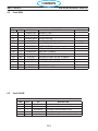
ESAB PowerCut 1600 User manual
- Category
- Welding System
- Type
- User manual
Ask a question and I''ll find the answer in the document
Finding information in a document is now easier with AI
Related papers
-
ESAB Secondary Power Board Assembly Installation guide
-
-
-
-
-
ESAB ESP-101 User manual
-
-
-
-
Other documents
-
Manson VWM-4108 User manual
-
Scotsman Replacement Transformer - 17-2520-01 Operating instructions
-
Maytag 12001454 User manual
-
Big Ass Fans Essence User guide
-
Panasonic ASCT1F46E User manual
-
Miller KC000000 Owner's manual
-
 SEAV LG 2234 User guide
-
-
Cebora BRAVO 155 COMB User manual
-
