Page is loading ...

1
3-90-30007512Vermont Castings • Encore® Model 2040-CAT-C Installation Manual_R6 • 12/19
SAFETY NOTICE: IF THIS APPLIANCE IS NOT
PROPERLY INSTALLED, OPERATED AND
MAINTAINED, A HOUSE FIRE MAY RESULT.
TO REDUCE THE RISK OF FIRE, FOLLOW THE
INSTALLATION INSTRUCTIONS. FAILURE TO
FOLLOW INSTRUCTIONS MAY RESULT IN
PROPERTY DAMAGE, BODILY INJURY OR EVEN
DEATH. CONTACT LOCAL BUILDING OFFICIALS
ABOUT RESTRICTIONS AND INSTALLATION
INSPECTION REQUIREMENTS IN YOUR AREA.
The French language version of this manual is available online: www.vermontcastings.com
La version française de ce manuel est disponible en ligne : www.vermontcastings.com
Please read this entire manual before
installation and use of this wood-burning
room heater.
Failure to follow these instructions could
result in property damage, bodily injury
or even death.
• Donotstoreorusegasolineorotherammablevapors
and liquids in the vicinity of this or any other appliance.
• Donotoverre-Ifanyexternalpartstartstoglow,you
areoverring.Closeaircontrols.Overringwillvoid
your warranty.
• Complywithallminimumclearancestocombustibles
asspecied.Failuretocomplymaycauseahousere.
WARNING
Testedandapprovedforusewithdry,seasonedcordwood
only. Do Not Burn Wet or Green Wood. Burning any other
type of fuel will void your warranty.
CAUTION
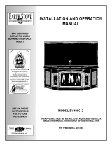
Installation & Operating Manual
Installation and Appliance Setup - Care and Operation
INSTALLER: Leave this manual with party responsible for use and operation.
OWNER: Retain this manual for future reference.
Call your dealer for questions on Installation, Operation, or Service.
2425
Encore NC Cover
5/05
For use in the
UnitedStatesandCanada
Encore
®
Model 2040-CAT-C
Wood Burning Stove
NOTICE: SAVE THESE INSTRUCTIONS
Installationandserviceofthisapplianceshouldbeperformedby
qualiedpersonnel.Hearth&HomeTechnologiesrecommends
HHTFactoryTrainedorNFIcertiedprofessionals.

2
3-90-30007512Vermont Castings • Encore® Model 2040-CAT-C Installation Manual_R6 • 12/19
CongratulationsonyourchoiceofaVermontCastingsEncore
®
Model2040-CAT-Cstove.Withthispurchaseyouhavemade
acommitmenttomakethehearthaplaceofwarmth,beautyandcomfortinyourhome.AtVermontCastings,weshare
thatjoyandappreciationforthehearth.Weassureyouthatyourcast-ironVermontCastingsstovehasbeenmadewiththe
utmost care and will provide you with many years of service.
Asyoubecomeacquaintedwithyournewstove,youwillndthatitsappearanceismatchedbyitsfunctionality,duetocast
iron’s unique ability to absorb and radiate heat.
Also,VermontCastingsproductsareamongthecleanest-burningwoodstoves available today.However,cleanburning
depends on both the manufacturer and the operator. Please read this manual carefully to understand how to properly operate
and maintain your stove.
AtVermontCastings,weareequallycommittedtoyoursatisfactionasacustomer.Thatiswhywemaintainanexclusive
networkofthenestdealersintheindustry.Ourdealersarechosenfortheirexpertiseanddedicationtocustomerservice.
Theyarefactory-trainedandknowledgeableabouteveryVermontCastingsproduct.FeelfreetocontactyourAuthorized
VermontCastingsDealeranytimeyouhaveaparticularquestionaboutyourstoveoritsperformance.
This manual contains valuable instructions on the installation and operation of your Vermont Castings Encore
®
Model
2040-CAT-C.Italsocontainsusefulinformationonmaintenance.Pleasereadthemanualthoroughlyandkeepitasareference.
Please read this entire manual before you install and use your new stove. Failure to follow instructions may result in property
damage,bodilyinjury,orevendeath.
Report #/Rapport # 0135WS042E / 0135WS042S
Tested to / Testé à: ASTM E2515, ASTM E2780, UL 1482-2011, ULC-S627-00, CAN/CSA B415.1
APPROVED FOR USE IN MOBILE HOMES IN THE U.S. AND CANADA.
Install and use only in accordance with manufacturer’s installation and operation instructions. Contact
local building or re ofcials about restrictions and installation inspection in your area. Install only with
legs provided in accordance with installation instructions.
WARNING: Risk of ame and smoke spillage. Do not obstruct the space beneath the heater.
Fuel: Use with solid wood fuel only. Do not burn other fuels. Build a re directly on hearth only. Do not
elevate re. Keep doors fully closed while operating.
Chimney: Use a minimum 6” or 8” diameter factory built high temperature (H.T.) chimney which is listed
to UL-103 (2100° F) or 8” X 8” nominal or larger approved masonry chimney with ue liner. Inspect
and clean chimney frequently - under certain conditions of use, creosote buildup may occur rapidly.
DO NOT CONNECT THIS UNIT TO A CHIMNEY FLUE SERVICING ANOTHER APPLIANCE
Chimney Connector: Use a minimum 6” or 8” diameter 24 gauge chimney connector. Install chimney
connector at least 30” from ceiling. Refer to local building codes and Vermont Castings Owner’s Guide
for special precautions for passing a chimney or chimney connector through a combustible wall or
ceiling.
Floor Protection: The Encore does not require R value oor protection. The minimum oor protector
material is 20 gauge sheet metal. Other oor protector materials that can be used include: Type I
hearth pads, ceramic tile, stone, brick, etc. Protection requirements vary somewhat between the
Untied States and Canada.
Optional Components: Flue Collar/8” oval Part No. 0555, Mobile Home Kit-0336, Fan Kit Part No.
FK26. 115V 60Hz 1.1 FLA
Replace glass only with Vermont Castings 5mm ceramic glass.
Do not remove or cover this label. Catalytic Combustor Part No. 30006623
CAUTION: Burning of materials other than the specied fuels may make the Catalyst in the combustor
inactive. The combustor is fragile, handle carefully.
Combustion air cannot be obstructed. Damper must be open before opening doors. Do not overre.
Glowing parts indicate overring.The space heater must be installed with the legs provided,
attached as shown in the installation instructions.
BARCODE LABEL
HF
Serial No.
N
o
de série:
3-90-30007511_R1
Date of Manufacture / Date de fabrication:
2019 2020 2021 JAN FEB MAR APR MAY JUN JUL AUG SEP OCT NOV DEC
Manufactured by / Fabriqué par: Hearth and Home Technologies 352 Mountain House Road, Halifax PA 17032
US ENVIRONMENTAL PROTECTION AGENCY
Certied to comply with 2020 US EPA particulate emissions standards at
1.1 g/hr. This wood heater contains a catalytic combustor which needs
periodic inspection and replacement for proper operation. Consult the
Owner’s Manual for further information. It is against Federal Regulations
to operate this wood heater in a manner inconsistent with operating
instructions in the Owner’s Manual.
MODEL / MODÈLE: “Encore
®
Model 2040-CAT-C”
LISTED SOLID FUEL ROOM HEATER BURNING FIREPLACE STOVE
HOMOLOGUE POELE A COMBUSTIBLE SOLIDES
MINIMUM CLEARANCES TO COMBUSTIBLE CONSTRUCTION / MINIMUM DE DEGAGEMENT
JUSQU’A LA CONSTRUCTION COMBUSTIBLE
Installez et utilisez uniquement conformément aux instructions d’installation et d’utilisation du
fabricant. Contactez les responsables locaux de la construction ou les services d’incendie
pour connaître les restrictions et l’inspection de l’installation dans votre région. Installez
uniquement avec les pieds fournis conformément aux instructions d’installation.
Avertissement: Risque de ammes et de fumée. Ne pas obstruer l’espace sous le radiateur.
Combustible: Utilisez uniquement du combustible à bois solide. Ne brûlez pas d’autres
combustibles. Construire un feu directement sur le foyer seulement. Ne pas élever le feu.
Gardez les portes complètement fermées pendant le fonctionnement.
Cheminée: Utilisez une cheminée haute température (H.T.) construite en usine et d’un
diamètre minimum de 6 ”ou 8”, qui est homologuée UL-103 (2100 ° F) ou une cheminée
en maçonnerie nominale ou supérieure approuvée de 8 ”X 8” avec conduit de cheminée.
Inspectez et nettoyez fréquemment la cheminée - dans certaines conditions d’utilisation, une
accumulation de créosote peut se produire rapidement.
Ne connectez pas cet appareil à un conduit de cheminée desservant un autre appareil
Raccord de cheminée: Utilisez un raccord de cheminée de calibre 24 minimum de 6 ”ou 8”
de diamètre. Installez le raccord de cheminée à au moins 30 po du plafond. Reportez-vous
aux codes du bâtiment locaux et au Guide du propriétaire de Vermont Castings pour connaître
les précautions particulières à prendre pour faire passer une cheminée ou un connecteur de
cheminée à travers un mur ou un plafond inammable.
Protection de sol: Encore ne nécessite pas de protection de plancher de valeur R. Le
matériau de protection de plancher minimum est une tôle de calibre 20. Parmi les autres
matériaux de protection de sol pouvant être utilisés, citons: les coussinets de foyer de type I,
les carreaux de céramique, la pierre, la brique, etc.
Composants facultatifs: collier de cheminée / ovale de 8 po (réf. 0555), kit pour maison
mobile-0336, kit de ventilateurs (réf. FK26). 115V 60Hz 1.1 FLA
Remplacez le verre uniquement par du verre en céramique de 5 mm Vermont Castings.
Ne pas enlever ni recouvrir cette étiquette. Système de combustion catalytique N ° de pièce
30006623
Attention: La combustion de matériaux autres que les carburants spéciés peut rendre le
catalyseur dans la chambre de combustion inactif. La chambre de combustion est fragile,
manipulez-la avec précaution.
CAUTION:HOT WHILE IN OPERATION- DO
NOT TOUCH- KEEP CHILDREN AND CLOTHING AWAY-
CONTACT MAY CAUSE SKIN BURNS- SEE NAMEPLATE
AND INSTRUCTIONS. KEEP FURNISHINGS AND
OTHER COMBUSTIBLE MATERIALS A CONSIDERABLE
DISTANCE AWAY FROM THE APPLIANCE
ATTENTION:CHAUD LORS
DU FONCTIONNEMENT- NE TOUCHEZ
PAS L’APPAREIL-GARDEZ LES ENFANTS ET LES
VÊTEMENTS ÉLOIGNÉS- TOUT CONTACT PEUT
ENTRAÎNER DES BRÛLURES DE LA PEAU. RÉFÉREZ-
VOUS À LA PLAQUE SIGNALÉTIQUE ET AU MODE
D’EMPLOI. GARDEZ LE MOBILIER ET LES AUTRES
MATÉRIAUX COMBUSTIBLES BIEN À L’ÉCART DE
L’APPAREIL.
*Less than 3/4” (19mm) protrusion. For additional types of installations and clearances consult your
Owner’s Manual. Por autres modes d’installation et degagement supplementaires, consultz votres
manual du proprietaire.
Most vertical installations require a ceiling heat shield and a ue collar heat shield to be installed.
Consult your Owner’s Manual.
A = Unit to Sidewall 19”
B = Unit to Backwall 20”
C = Chimney Connector to Sidewall 29”
D = Chimney Connector to Backwall 21”
E = Unit to Adjacent Wall 18-1/2”
F = Sides (Floor Protection) 6”
G = Front to Glass (Floor Protection) 16”
H = Rear (Floor Protection) 6”
I = Top to Bottom of Mantel 22”
J = Top to Bottom of Top Trim* 28”
K = Edge of Top to Side Wall 21”
A = Entre le mur lateral et l’appareil 483mm
B = Entre le mur arriereet l’appareil 508mm
C = Entre le tuyau et le mur lateral 737mm
D = Entre le tuyau et le mur arriere 534mm
E = Entre le mur adjacent et l’appareil 470mm
F = Côtes (la protection de plancher) 203mm
G = Devant, par rapport au verr 457mm
H = Arrière (la protection de plancher) 203mm
I = De haut en bas de Mantel 556mm
J =
De haut en bas de la moulure supérieure* 712mm
K = Edge of Haut de paroi latérale 534mm
E
E
A
B
C
D
G
F
H
F
J
K
I
MINIMUM FLOOR
PROTECTION
HEARTH
INSTALLATION
Made in U.S.A. of US and imported parts.
Fabriqué aux États-Unis-d’Amérique par des pièces d’origine américaine et pièces importées.
LABEL TICKET
ECO: 89484 LABEL SIZE: 4.75” H x 15.75” W
PART # / REV: 3-90-30007511 ADHESIVE:
ORIGINATOR: Spidlet MATERIAL: 24 Gauge Aluminum
DATE: 03/05/19 INK: Black Background
ALL CAUTION LITERATURE IN RED
(4) Holes = .156 x .250, Corners .062
Barcode label must have the serial number on it. The
barcode label must be able to read Code 39 Full ASCII.
352 Mountain House Road
Halifax, PA 17032
Serial No.
SAMPLE
TestLab&ReportNo.
Model Name
Mfg. Date
US ENVIRONMENTAL PROTECTION AGENCY
Certiedtocomplywith2020particulateemissionstandards.
Please read this entire manual before you install and use
your new stove. Failure to follow instructions may result in
propertydamage,bodilyinjury,orevendeath.

3
3-90-30007512Vermont Castings • Encore® Model 2040-CAT-C Installation Manual_R6 • 12/19
1ProductSpecicandImportantSafetyInformation
A.ApplianceCertication. . . . . . . . . . . . . . . . . . . . . . . . 4
B.Californiasafetyinformation ................... 4
C.BTU&EciencySpecications ................ 4
D. Stove Dimensions ........................... 5
2 Installation
A.OutsideAir. . . . . . . . . . . . . . . . . . . . . . . . . . . . . . . . . 6
B.TypesofChimneytoUse ..................... 6
C.ChimneySize .............................. 7
D.ChimneyConnectorGuidelines ................ 7
E.FireplaceInstallations ........................ 9
F. Floor Protection .............................11
G.ClearancestoCombustibles .................. 12
H.MobileHomeInstallation. . . . . . . . . . . . . . . . . . . . . 18
3 Assembly
A.SettingupyourStove ....................... 19
B.AssembletheRemovableInsertHandle ......... 19
C.InstallBottomHeatShield. . . . . . . . . . . . . . . . . . . . 20
D.AdjustLegLevelers. . . . . . . . . . . . . . . . . . . . . . . . . 20
E.ReverseFlueCollar ........................ 20
F.AttachedDamperHandle. . . . . . . . . . . . . . . . . . . . . 20
G.InstallingCatalystTemperatureProbe .......... 20
H.AttachPrimaryAirThermostatHandle .......... 20
I.FanKitInstallation .......................... 21
J.Installing/RemovingCatalyst .................. 21
4 Smoke Alarm / Safety Tips
A.SmokeandCODetectors .................... 22
B. Safety Tips ............................... 22
5 Operation
A.AirControls ............................... 23
B.DamperAdjustment. . . . . . . . . . . . . . . . . . . . . . . . . 23
C.ConditioningYourStove ..................... 24
D.WoodBurningOperation .................... 24
E.AddingFuel ............................... 25
F.AshDisposal .............................. 27
G. Draft Management ......................... 29
6 Maintenance
A.GlassMaintenance ........................ 31
B.DamperAdjustment. . . . . . . . . . . . . . . . . . . . . . . . . 32
C.GasketReplacement ....................... 32
D.TheChimneySystem ....................... 33
E.TheCatalyticElement ....................... 35
7 Service Parts List .......................... 37
8 Warranty ................................. 44
TABLE OF CONTENTS
Safety Alert Key:
• DANGER! Indicatesahazardoussituationwhich,ifnotavoidedwill result in death or serious injury.
• WARNING!Indicatesahazardoussituationwhich,ifnotavoidedcould result in death or serious injury.
• CAUTION! Indicatesahazardoussituationwhich,ifnotavoided,could result in minor or moderate injury.
• NOTICE:Indicatespracticeswhichmaycausedamagetotheapplianceortoproperty.
=Containsupdatedinformation

4
3-90-30007512Vermont Castings • Encore® Model 2040-CAT-C Installation Manual_R6 • 12/19
*An eciency based on EPA historical data.
**Maximum calculated eciency using Douglas Fire
dimensional lumber and data collected during EPA
emissions test.
***A range of BTU outputs based on EPA Default Eciency
and the burn rates from the low and high EPA tests, using
Douglas Fir dimensional lumber.
**** A peak BTU out of the unit calculated using the maximum
rst hour burn rate from the High EPA Test and BTU content
of seasoned cordwood (8600) times the eciency.
This wood heater needs periodic inspection and repair for
properoperation.Itisagainstfederalregulationstooperate
this wood heater in a manner inconsistent with operating
instructions in this manual.
EPACerticationNumber: 164-18
Catalytic Information
EPACertiedEmissions: 1.1g/hr
*EPADefaultEciency: 78.0%
**ActualtestedEciency: 76.8%
***EPA BTU Output: 12,800-37,100
****Peak BTU/Hour Output: 41,500
Other Important Information
Vent Size:
6Inch(152mm)
8Inch(203mm)
Firebox Size: 2.3 cu. ft.
Max. Wood Length: 22"Maximum
Ideal Wood Length: 18"(TopLoad)
Fuel
SeasonedCordwood
(20%moisture)
Area Heated...................................900-2,300Squarefeet
Loading .......................................................... Front and top
Chimney Connector: .........................................................
for6"uecollar ...........................6"(152mm)diameter
for8"ovaluecollar ....................8"(203mm)diameter
Flue Exit Position ............................................ToporRear
Primary Air ............
Manuallyset,thermostaticallymaintained
Secondary Air ................................... Fixed,self-regulating
Ash Handling System........................ Removableashpan
Glass Panels .............................High-temperatureceramic
Weight ......................................................475lbs.(215kg.)
Mobile Home Approved
This appliance is approved for Installation in mobile/
manufactured homes in the United States and Canada
Thestructuralintegrityofthemobilehomeoor,ceilingand
walls must be maintained. The appliance must be properly
groundedtotheframeofthemobilehome,andmustnever
be installed in a room designated for sleeping. The unit must
have provisions for an outside air source when installed in
a mobile home.
B. California Safety Information
MODEL: Encore
®
Model2040-CAT-C
LABORATORY: OMNITestLaboratories,Inc
REPORT NO. 0135WS042E&0135WS042S
TYPE:
SolidFuelRoomHeater/Wood
Burning Type
STANDARD(s):
ASTME2515,ASTME2780,UL1482-
2011,ULC-S627-00,CAN/CSAB415.1
ELECTRICAL
RATING:
115VAC,60Hz
A.ApplianceCertication C.BTU&EciencySpecications
!
WARNING
This product and the fuels used to operate this product
(wood),andtheproductsofcombustionofsuchfuels,can
expose you to chemicals including carbon black, which
isknowntotheStateofCaliforniatocausecancer,and
carbonmonoxide,whichisknowtotheStateofCalifornia
to cause birth defects or other reproductive harm. For
more information go to: www.P65Warnings.ca.gov
Proposition 65 Warning:Fuelsusedingas,woodburning
oroil red appliances,andthe products ofcombustion
of such fuels, contain chemicals known to the State
of California to cause cancer, birth defects and other
reproductive harm.
CaliforniaHealth&SafetyCodeSec.25249.6
1
ProductSpecicandImportantSafetyInformation

5
3-90-30007512Vermont Castings • Encore® Model 2040-CAT-C Installation Manual_R6 • 12/19
D. Stove Dimensions
Figure 1.1
Drawing Not to Scale
5295
Encore 2N1
dimensions
3-3/4”
(95 mm)
22-3/4”
(578 mm)
25"
(635 mm)
Top exit
flue collar
height
27"
(686 mm)
25-3/4”
(654 mm)
18-1/2”
(470 mm)
7-1/4”
(184 mm)
27"
(686 mm)
22-1/4”
(565 mm)
15-1/2”
(394 mm)
5"
(127 mm)
2-7/8” (73 mm)
23-3/4”
(603 mm)
15"
(381 mm)
40-5/16”
(1024mm)

6
3-90-30007512Vermont Castings • Encore® Model 2040-CAT-C Installation Manual_R6 • 12/19
SAFETY NOTICE: IF YOUR APPLIANCE IS NOT
PROPERLY INSTALLED, A HOUSE FIRE MAY RESULT.
TO REDUCE THE RISK OF FIRE, FOLLOW THE
INSTALLATION INSTRUCTIONS. CONTACT LOCAL
BUILDING OR FIRE OFFICIALS ABOUT RESTRICTIONS
AND INSTALLATION INSPECTION REQUIREMENTS
IN YOUR AREA.
Beforeyoubeginaninstallation,besurethat:
• Yourstoveandchimneyconnectorwillbefarenoughfrom
combustible material to meet all clearance requirements.
• The oor protector is large enough and is constructed
properly to meet all requirements.
• Youhaveallnecessarypermitsfromlocalauthorities.
Yourlocalbuildingocialisthenalauthorityforapproving
your installation as safe and determining that it meets local
and state codes.
The metal label permanently attached to the back of every
VermontCastings’stoveindicatesthatthestovehasbeen
tested to current UL and ULC standards, and gives the
name of the testing laboratory. Clearance and installation
information also is printed on the label. When the stove is
installed according to the information both on the label and
inthismanual,localauthoritiesusuallywillacceptthelabel
as evidence that the installation meets codes and can be
approved.
However,codesvaryindierentareas.Beforestartingthe
installation,reviewyourplanswiththelocalbuildingauthority.
Your local dealer can provide any additional information
needed.
Foranyunresolvedinstallationissues,refertotheNational
Fire ProtectionAssociation’s publicationANSI/NFPA 211
Standard for Chimneys, Fireplaces, Vents and Solid Fuel
BurningAppliances.ForCanada,theequivalentpublication
isCSACAN-B365InstallationCodeforSolidFuelBurning
AppliancesandEquipment.Thesestandardsarethebasisfor
manynationalcodes.Theyarenationallyrecognizedandare
acceptedbymostlocalauthorities.Yourlocaldealeroryour
localbuildingocialmayhaveacopyoftheseregulations.
IMPORTANT: Failure to follow these installation
instructions may result in a dangerous situation, including
achimneyorhousere.Followallinstructionsexactly,
and do not allow makeshift compromises to endanger
property and personal safety.
A. Outside Air
Asourceofair(oxygen)isnecessaryinorderforcombustion
to take place. Whatever combustion air is consumed by the
remustbereplaced.Airisreplacedviaairleakagearound
windowsandunderdoors.Inhomesthathavetightlysealed
doorsandwindows,anoutsideairsourceisneeded.
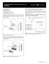
Items Needed for Installation (not supplied)
• Outside air adapter (available at your authorized
VermontCastingsdealer)
• Phillips head screw driver
• Silicone sealant
• 3”FlexorRigidDuct
• 3”OutsideAirTerminationCapwithScreen
• HoseClamps
• Drills and saws necessary for cutting holes through
thewallorooringinyourhome.
1. Usinga#2Phillipsscrewdriverattachtheexadapterto
theapplianceusing4screws,Figure2.17.
2. Floor&RearInstallation:Cuta3”(76mm)holeinoutside
walloroortoaccommodateoutsideairpiping.Use3”
(76mm) aluminum metalex or rigidpiping to directly
connect outside air to appliance intake. Use a termination
capwitharodentscreen(notsupplied).Sealbetweenthe
wall(oroor)andthepipewithsiliconetopreventmoisture
penetration.
Whenpoordraftiscausedbyalowinltrationrate,openinga
groundoorwindowonthewindwardsideofthehouseand
near the stove will usually alleviate the problem.
Abettersolutionistoinstallapermanentoutsideairsupply
tothestoveand/orroom.Infact,bringingairforcombustion
from outside the home directly to the air inlet of the stove is
required for new construction in some areas.
B. Types of Chimney to Use
Youmustconnectthisappliancetoacode-approvedmasonry
chimneywithaueliner,toarelinedmasonrychimneythat
meetslocalcodes,ortoaprefabricatedmetalchimneythat
complieswiththerequirementsforTypeHTchimneysinthe
StandardforChimneys,Factory-Built,ResidentialTypeand
BuildingHeatingAppliance,UL103.Figure2illustratesthe
two types. The chimney and chimney connector must be in
good condition and kept clean.
2
Important Safety Information

7
3-90-30007512Vermont Castings • Encore® Model 2040-CAT-C Installation Manual_R6 • 12/19
2' Min.
2' Min.
3'
Min.
0 To 10'
3'
Min.
0 To 10'
AC617
RLTSKC8
2/11/98
Reference
Point
Figure 2.2-The2’-3’10’ChimneyRule.
Masonry Chimneys
Aninspectionofthechimneymustconrmthatithasalining.
Do not use an unlined chimney. The chimney should have
no cracks, loose mortar, other signs of deterioration, and
blockage. Repair any defectsbefore thechimney isused
with your stove.
Unusedopeningsinanexistingmasonrychimneymustbe
sealedwithmasonrytothethicknessofthechimneywall,
andthechimneylinershouldberepaired.Openingssealed
with pie plates or wallpaper are a hazard and should be
sealedwithmortarorrefractorycement.Intheeventof a
chimneyre,amesandsmokemaybeforcedoutofthese
unused thimbles.
The chimney should be thoroughly cleaned before use.
A newly-built masonry chimney must conform to the
standardsofyourlocalbuildingcodeor,intheabsenceofa
localcode,toarecognizednationalcode.Masonrychimneys
mustbelined,eitherwithcode-approvedmasonryorpre-cast
refractory tiles, stainless steel pipe, or a code-approved,
“poured-in-place”liner.Thechimney’sclean-outdoormust
seal tightly. A loose or leaky clean-out door can weaken
chimneydraft,causingperformanceproblems.
Prefabricated Chimneys
A prefabricated metal chimney must be one tested and
listedforusewithsolid-fuelburningappliancestotheHigh-
Temperature(H.T.)ChimneyStandardUL-103-1985(2100°F)
fortheUnitedStates,andHighTemperature(650°C)Standard
ULCS-629forCanada.
DO NOT CONNECT THIS UNIT TO A CHIMNEY FLUE
SERVING ANOTHER APPLIANCE.
C. Chimney Size
Thisappliancewithan8"(203mm)uecollarisapproved
forventingintoamasonrychimneywithanominaluesize
of8"x8"(203x203mm)or8"x12"(203x305mm),and
intoarounduewithnominaluesizeof8"(203mm).This
appliancewitha6"(152mm)ueconnectorisapprovedfor
ventingintoamasonrychimneywithanominaluesizeof
8"x8"(203x203mm),andintoarounduewithnominal
ueof6"(152mm).
Whatevertheuecollarsize,thisappliancemaybevented
into larger chimneys as well. However, chimneys with
linerslargerthan8"x12"(203x305mm)mayexperience
rapidcoolingofsmokeandreductionindraft,especiallyif
the chimneys are located outside the home. These large
chimneysmayneedtobeinsulatedorhavetheiruesrelined
for proper stove performance.
Accessoriestohelpmaketheconnectionbetweenstainless
steel chimney liners and your appliance are available through
your local dealer.
D. Chimney Connector Guidelines
Achimneyconnectoristhe single-wallpipethatconnects
the stove to the chimney. The chimney itself is the masonry
orprefabricatedstructurethatenclosestheue.Chimney
connectors are used only to connect the stove to the chimney.
Single-wall connectors should be made of 24 gauge or
heavier steel. Do notuse galvanizedconnector; it cannot
withstand the high temperatures that can be reached by
smoke and exhaust gases, and may release toxic fumes
underhighheat.Theconnectormaybe6"(152mm)or8"
(203mm)indiameter.
Ifpossible, donotpass thechimney connector througha
combustiblewallorceiling.Ifpassagethroughacombustible
wall is unavoidable, refer to the section on Wall Pass-
Throughs.Donotpasstheconnectorthroughanattic,acloset
or similar concealed space. The whole connector should be
exposedandaccessibleforinspectionandcleaning.
ST241
chimney types
12/13/99 djt
Aprefabricateddouble-wall
insulated chimney
Atile-lined
masonry chimney
Figure 2.1-Approvedchimneytypes.
Ifyouuseanexistingmasonrychimney,itmustbeinspected
to ensure it is in a safe condition before the stove is installed.
Yourlocalprofessionalchimneysweep,buildinginspector,
orredepartmentocialwillbeabletoinspectthechimney
or provide a referral to someone who can.
Thechimneymustextendatleast3’(914mm)abovethe
highestpointwhereitpassesthroughorneararoof,andat
least2’(610mm)higherthananypartofabuildingwithin
10’(3m)horizontally.(Figure2.2)
Forproperdraftandgoodperformance,anychimneyused
shouldextendatleast16’(5m)abovetheuecollarofthe
stove.

8
3-90-30007512Vermont Castings • Encore® Model 2040-CAT-C Installation Manual_R6 • 12/19
Inhorizontalrunsofunshieldedchimneyconnector,maintain
adistanceof30"(762mm)fromtheceiling.Keepitasshort
and direct as possible, with no more than two 90° turns.
Slope horizontal runs of connector upward 1/4" per foot
(6mmpermeter)goingfromthestovetowardthechimney.
Therecommendedmaximumlengthofahorizontalrunis3’
(1m),andthetotallengthshouldbenolongerthan8’(2.4
m).Incathedralceilinginstallations,extendtheprefabricated
chimneydownwardtowithin8’(2.4m)ofthestove.Thiswill
helpmaintainagooddraftbykeepingthesmokewarm,so
that it rises readily.
Wearglovesandprotectiveeyewearwhendrilling,cuttingor
joining sections of chimney connector.
Single-wall Chimney Connectors
• Beginassemblyattheuecollarofthestove.Insertthe
rst crimped end into the
stove’suecollar,andkeep
each crimped end pointing
toward the stove, Figure
2.3. Using the holes in the
ue collar as guides, drill
1/8" (3 mm) holes in the
bottomoftherstsection
of chimney connector and
secureittotheuecollar
withthree#10x1/2"sheet
metal screws. Lift o the
griddle, and shield the
stove’s surface between
the griddle opening and the
frontoftheuecollartoprotectthenishwhenyoudrill
the front hole.
• Fasteneachjointbetweensectionsofchimneyconnector,
includingtelescopingjoints,withatleastthree(3)sheet
metal screws. The pre-drilled holes in the top of each
section of chimney connector serve as guides when you
drill1/8"(3mm)holesinthebottomofthenextsection.
• Fastenthechimneyconnectortothechimney.Instructions
for various installations follow. Figure 2.4 illustrates the
general layout of chimney connector parts.
• Be sure the installed stove and chimney connector are
correct distances from nearby combustible materials.
NOTE: Special slip pipes and thimble sleeves that form
telescoping joints between sections of chimney connector
are available to simplify installations. They often eliminate
theneedtocutindividualconnectorsections.Consultyour
local dealer about these special pieces.
ST492
Defiant
freestanding
installation
11/00
Chimney
Elbow
Slip Pipe
Standard
Connector
FlueCollar
Thimble
FlueInner
Flue
Figure 2.4 -An exploded view of the chimney connection in a
freestanding masonry installation.
ST242
Chimney connector
12/13/99 djt
Flue Gas
Direction
Toward
Stove
Figure 2.3
Securing the Single-wall Connector to a Prefabricated
Chimney
Follow the installation instructions of the chimney manufacturer
exactlyasyouinstallthechimney.Themanufacturerofthe
chimneywillsupplytheaccessoriestosupportthechimney,
eitherfromtheroofofthehouse,attheceilingoftheroom
wherethestoveisinstalled,orfromanexteriorwall.
Special adapters are available from your local dealer to
make the connection between the prefabricated chimney and
the chimney connector. The top of such adapters attaches
directly to the chimney or to the chimney’s ceiling support
package,whilethebottomoftheadapterisscrewedtothe
chimney connector.
Theseadaptersaredesignedsothetopendwilltoutside
theinnerwallofthechimney,andthebottomendwilltinside
therstsectionofchimneyconnector.
Securing the Single-wall Connector to a Masonry
Chimney
Bothfreestandingmasonrychimneysandreplacemasonry
chimneys may be used for your installation.
Freestanding Installations
Ifthechimneyconnectormustpassthroughacombustible
walltoreachthechimney,followtherecommendationsin
the Wall Pass-Through section that follows. The opening
through the chimney wall to the ue (the “breech”) must
belinedwitheitheraceramicormetalcylinder,calledthe
“thimble,”whichiscementedsecurelyinplace.Mostchimney
breechesincorporatethimbles,butthetmustbesnugand
the joint between the thimble and the chimney wall must be
cementedrmly.

9
3-90-30007512Vermont Castings • Encore® Model 2040-CAT-C Installation Manual_R6 • 12/19
Figure 2.6-Inthisinstallation,thechimneyconnectorattachesto
thechimneyabovethereplaceopening.
ST244
Plymouth
fplc over mantel
12/99
*
*
CheckThese
Clearances
Mantel
Seal
ThisO
ST243
thinble connection
12/13/99 djt
Thimble Sleeve
Chimney
Connector
Flue
Keepsleeve
endushwith
uetile
Figure 2.5-Thethimble,madeofeitherceramicormetal,must
be cemented securely in place.
• Thereplacedampermustbesealedtopreventroomair
fromescapinguptheue.However,itmustbepossible
tore-openthedampertoinspectorcleanthechimney.
Through the Fireplace
If your replace opening height is at least 29" (737 mm),
you may install your appliance through the opening using
a“positiveconnection”kit,availablefromyourlocaldealer.
Positiveconnectionkitsensureatighttbetweenthestove
uecollarandthechimneyue,Figure2.7.
Fireplaceinstallations,whetherconnectedtotheueabove
or through the replace opening, have special clearance
requirementstoadjacenttrimandthemantel.You’llndthe
requiredsafeclearancesforreplaceinstallationsonPage
12.
Floor protection requirements also apply to fireplace
installations.Refertothe"FloorProtection"sectioninthis
manual.
Wall Pass-Throughs
Wheneverpossible,designyourinstallationsotheconnector
does not pass through a combustible wall. If you are
consideringawallpass-throughinyourinstallation,check
withyourbuildinginspectorbeforeyoubegin.Also,check
with the chimney connectormanufacturer for any specic
requirements.
Accessoriesareavailableforuseaswallpass-throughs.If
usingoneofthese,makesureithasbeentestedandlisted
foruseasawallpass-through.
Toinstallathimblesleeve,slideitintothebreechuntilitis
ushwiththeinneruewall.Donotextenditintotheactual
uepassage,asthiscouldinterferewiththedraft.
Thethimblesleeveshouldprotrude1-2"(25-50mm)intothe
room. Use furnace cement and thin gasketing to seal the
sleeve in place in the thimble. Secure the chimney connector
to the outer end of the sleeve with sheet metal screws.
Withoutathimble,asuitablelengthofchimneyconnector
canbeextendedthroughthebreechtotheinnerfaceofthe
ueliner,andcementedsecurelyinplace.Additionalpieces
of connector are then attached with sheet metal screws.
E. Fireplace Installations
The chimney connector may be connected to the chimney
abovethereplaceopeningorthroughthereplace.
Above the Fireplace
Your appliance may be connected to a chimney above a
replaceopening,Figure2.6.Insuchinstallations,thestove
ispositionedonthehearthinfrontofthereplaceandthe
chimney connector rises from the stove top and then angles
ninety degrees back into the chimney. The chimney liner
shouldextendtothepointatwhichthechimneyconnector
enters the chimney.
If the chimney connector in your installation enters the
chimneyaboveareplace,followalltheguidelinesmentioned
aboveforfreestandinginstallations.Inaddition,givespecial
consideration to the following points:
• Check the clearance between the mantel and the
chimney connector, and any combustible trim or the
mantel.
• Checktheclearancebetweenthechimneyconnectorand
theceiling.Theclearanceshouldbeatleast30"(762
mm)withunshieldedconnectors.Consulttheclearance
charts for other installation options.
Aspecialpiececalledthe“thimblesleeve,”slightlysmaller
in diameter than standard connectors and most thimbles,
will facilitate the removal of the chimney connector system
forinspectionandcleaning,Figure2.5.Thimblesleevesare
available from your local dealer.

10
3-90-30007512Vermont Castings • Encore® Model 2040-CAT-C Installation Manual_R6 • 12/19
ST245
fireplace
flex connector
12/99
Flexible
Connector
Mantel Shield
FireplaceAdapterKit
“PositiveConnection”
Figure 2.7-Throughthereplaceinstallation.
ST493
Brick pass thru
11/00
Wall Stud
Chimney
Connector
Floor
Protection
12" of
Noncombustible
Material
Figure 2.8-Anapprovedwallpass-throughfortheUnitedStates.
T
ST494
steel
wall pass thru
11/00
18"(460mm)clearance
between pipe and
sides/top/bottomof
opening
Figure 2.9-Anapprovedwallpass-throughforCanada.
Yourlocaldealeroryourlocalbuildinginspectorcanprovide
details for other approved methods of passing a chimney
connectorthroughacombustiblewallinyourarea.InCanada,
this type of installation must conform to CAN/CSA-B365,
Installation Code for Solid Fuel Burning Appliances and
Equipment.
NOTE:Donotventyourapplianceintoafactory-built(zero-
clearance)replace.Theseappliancesandtheirchimneys
arespecicallydesignedasaunitforuseasreplaces.It
mayvoidthelistingorbehazardoustoadaptthemforany
other use.
DO NOT CONNECT THIS APPLIANCE TO ANY AIR
DISTRIBUTION DUCT OR SYSTEM.
ThreeothermethodsarealsoapprovedbytheNFPA:
• Placing a section of chimney connector inside a ventilated
thimble,whichinturnisseparatedfromcombustiblesby
6"(152mm)ofberglassinsulatingmaterial.
• Placing a section of chimney connector inside a section
of 9" (230 mm) diameter, solid-insulated, factory-built
chimney, with 2" (51 mm) of air space between the
chimney section and combustibles.
• Using a section of solid-insulated double-wall high
temperaturechimney,withaninsidediameterthesameas
thechimneyconnector,atleastoneinchofsolidinsulation,
andaminimumof9"(229mm)airspacebetweenthe
outer wall of the chimney section and combustibles.
In Canada, The Canadian Standards Association has
establisheddierentguidelinesforwallpass-throughs.Figure
2.9showsonemethod,inwhichallcombustiblematerialin
thewalliscutawaytoprovidetherequired18"(457mm)
clearance for the connector. The resulting space must remain
empty.Aush-mountedsheetmetalcovermaybeusedon
onesideonly.Ifcoversmustbeusedonbothsides,each
cover must be mounted on noncombustible spacers at least
1"(25mm)clearofthewall.
IntheUnitedStates,theNationalFireProtectionAssociation
(NFPA) has established guidelines for passing chimney
connectors through combustible walls. Many building
code inspectors follow these guidelines when approving
installations.
Figure 2.8 shows one NFPA recommended method.All
combustible material in the wall is cut away from the
single-wallconnectortoprovidetherequired12"(305mm)
clearance.Anymaterialusedtocloseuptheopeningmust
be noncombustible.

11
3-90-30007512Vermont Castings • Encore® Model 2040-CAT-C Installation Manual_R6 • 12/19
F. Floor Protection
Atremendousamountofheatradiatesfromthebottomplate
ofyourstove.Theoorareadirectlyunderandaroundthe
stove will require protection from radiant heat as well as from
straysparksorembersthatmayescapetherebox.
HeatprotectionisprovidedwiththeuseoftheBottomHeat
Shield supplied with the stove.
Most installations will require the bottom heat shield to be
attached. Onlywhen the stoveis placed on a completely
noncombustible surface such as unpainted concrete over
earth may it be used without the heat shield.
With the bottom heat shield installed this appliance was
tested with spark and ember protection only. There is no
required"R"value,andtheoorprotectoronlyneedstobe
anon-combustiblematerial,e.g.ceramictileorsheetmetal.
Important:Allinstallationsonacombustibleoorrequire
the use of the supplied bottom heat shield.
TheEncoredoesnotrequireRvalueoorprotection.
Theminimumoorprotectormaterialis20gaugesheetmetal.
OtheroorprotectormaterialsthatcanbeusedincludeType
Ihearthpads,ceramictile,stone,brick,etc.
Protection requirements vary somewhat between the Untied
StatesandCanadaasfollows:
In U. S. installationstheoorprotectorisrequiredunderthe
stoveandmustextendatleast16"(notincludingtheashlip)
fromthefrontofthestove(“F,”Figure2.10),andatleast6"
fromthesidesandrear.(“D”and“E,”Figure2.10)
In rear venting congurations, oor protection must also
extendunderthechimneyconnectorand2"toeitherside.
(“C,” Figure 2.10) For the 8" (203 mm) connector, the
protectormustbeaminimumof12"(305mm)wide.Forthe
6"(152mm)connector,theprotectormustbe10"(254mm)
wide. The protector must be centered under the connector.
Tomeettheserequirements,aoorprotectormustbeatleast
39" wide and 45" deep.
In Canada:A noncombustible oor protector is required
underthestoveaswell.Theoorprotectormustextend18"
(457mm)tothefront(“F,”Figure2.10),and8"(203mm)from
thesidesandrear.(“D”and“E,”Figure2.10)
Tomeettheserequirements,aoorprotectormustbeatleast
43"(1092mm)wideand49"(1245mm)deep.
U.S. Canada
A 39" 43"(1092mm)
B 45" 49"(1245mm)
C
12"
10"
12"(305mm)8"Connector
10"(250mm)6"Connector
D 6" 8"(203mm)
E 6" 8"(203mm)
F 16" 18"(460mm)
D
E
A
B
A
E
C
ST500
Defiant
floor protection
1/31/02 djt
F
E
E
F
Figure 2.10-Requiredoorprotectiondimensions.

12
3-90-30007512Vermont Castings • Encore® Model 2040-CAT-C Installation Manual_R6 • 12/19
G. Clearance to Combustibles
Keep the Stove a Safe Distance From Surrounding
Materials
Both a stove and its chimney connector radiate heat in all
directionswhenoperating,andnearbycombustiblematerials
can overheat dangerously if they are too close to the heat
source.Asafeinstallationrequiresthatadequateclearance
be maintained between the hot stove and its connector and
nearby combustibles.
Clearance is the distance between either your stove or
chimney connector, and nearby walls, oors, the ceiling,
andanyotherxedcombustiblesurface.Thisappliancehas
specicclearancerequirementsthathavebeenestablished
after careful research and testing. These clearance
requirements must be strictly observed.
Inaddition,keepfurnishingsandothercombustiblematerials
away from the stove. In general, a distance of 48" (1219
mm)mustbemaintainedbetweenthestoveandmovable
combustible items such as drying clothes, furniture,
newspapers,rewood,etc.Keepingthoseclearanceareas
empty assures that nearby surfaces and objects will not
overheat.
Safe Ways to Reduce Clearances
Clearance requirements are established to meet every
installationpossibility,andtheyinvolvethecombinationof
these variables:
• When the stove pipe has no listed heat shield mounted
on it.
• When the wall has no heat shield mounted on it.
• When the wall has a heat shield mounted on it.
• When the wall and stove pipe have heat shields.
Ingeneral,thegreatestclearanceisrequiredwhenyouplace
a stove and its connector near a wall with no heat shield.
For example, when this appliance is installed using 6"
connector pipe parallel to the rear wall and no connector
shieldis used,it mustbe at least10" (254mm) from the
wallbehinditandatleast19"(483mm)fromwallsoneither
side. These dimensions are measured from the back of the
rear shroud and the side edge of the cast iron top to the
combustible wall.
Ifthisapplianceisinstalledinacornerandnoshieldisused,
thecornersofthestovetopmustbeatleast18-1/2"(470
mm)fromnearbywalls.
Clearancesmaybereducedonlybymeansapprovedbythe
regulatoryauthority,andinaccordancewiththeclearances
listedinthismanual.Refertotheclearancechartforapproved
clearancereductionspecications.
NOTE: Installation of this appliance is not permitted in
alcoves.
ST248
wall shield construction
12/14/99 djt
Stud Wall
Framing
Wall Shield
Noncombustible
Spacers and
Fasteners
Drywall
AirFlow
AirFlow
Screen
Shield
Metal
Spacer
Figure 2.11-Approvedwallshieldconstruction.
Theshieldmustbeaminimumof48"(1219mm)tall,and
mustextendatleast19"(483mm)higherthanthetopofthe
stove,whicheverishigher.Theshieldbehindthechimney
connectormustbe30"(760mm)wide,centeredbehindthe
pipe; for installations that use an approved prefabricated
chimneytopassthroughtheceiling,theshieldbehindthe
chimneyconnectormuststop1"(25mm)belowtheceiling.
With8"connectionsandchimneys,becauseofpotentially
higher pipe temperatures, the shield must extend the full
height ofthe wall (up to 9’ (2.7 m)) and stop 1" (25 mm)
below the ceiling.
Wall Shields
One way to reduce clearances is with a wall shield
constructedof24gaugeorheaviersheetmetal,orofanother
noncombustible material such as 1/2" (13 mm) insulation
board such as Durock
®
or Wonderboard
®
,orcommonbrick
“laidonat,”withthe3-1/2"(90mm)sidedown.
Shields must be spaced out from the combustible surface 1"
(25mm)onnoncombustiblespacers,asinFigure2.11.The
spacers should not be directly behind the stove or chimney
connector.
Airmustbeabletoowbetweenthewallandtheshield.At
least50%ofthebottom1"(25mm)oftheshieldmustbe
open,andtheshieldmustbeopenatthetop.Metalscreening
across the top will keep small stray objects from being trapped
behindtheshield,Figure2.11.

13
3-90-30007512Vermont Castings • Encore® Model 2040-CAT-C Installation Manual_R6 • 12/19
48"
(1220 mm)
ST497
Defiant
wall shield A
11/00
48"
(1220 mm)
Figure 2.12-Parallelinstallation,verticalchimneyconnector,two
wallshields.Reducedclearancesforbothrearandsidewalls.Wall
shields may meet at corner if desired. Shielding for connector is
centered behind connector.
48"
(1220 mm)
ST498
Defiant
Wall shield B
11/00
Figure 2.13-Parallelinstallationwithrearwallpass-through,two
wallshields.Reducedclearancestobothrearandsidewalls.Wall
shields may meet at corner if desired. Wall pass-through must
comply with codes.
Noncombustible shields
installed 1" (25 mm) away from
the combustible surface on
noncombustible spacers, called
ventilated shields, may be used
to reduce clearances.
To protect a mantel from the
heat of a stove in a fireplace
installation, use a custom-made
ventilated mantel shield that is
at least 48" (1220 mm) long,
centeredoverthestove.(Figure
15) Ventilated shields for side
trim must extend the full length
of the trim.
Anunprotected mantel(“A,” Figure 2.16)cannot be more
than9"(230mm)deepandmusthaveaminimumclearance
of28"(711mm),measuredfromthestove’stopplate.With
aventilatedshield,thisclearancemaybereducedsafelyto
15"(381mm).
Unprotected top trim (B) protruding 3/4" (19 mm) or less
from the face of the replace must be a minimum of 25"
(635mm)fromthestove’stopsurface.Thisclearancemay
be reduced safely.
Unprotectedsidetrim(C)thatprotrudes3/4"(19mm)orless
fromthefaceofareplacemusthaveaminimumclearance
of22"(554mm),measuredfromthestove’stopsideedge.
Ifthetrimextendsmorethan3/4"(19mm),itissubjectto
the requirements for wall clearance.
The charts and sample installations that follow list all the
clearancesrequiredforthevariousinstallationcongurations
of this appliance.
1" (25mm)
1/4" (6mm)
ST501
mantel and
trim shield
11/10/00 djt
Figure 2.15 -A custom-
formed mantel shield.
48"
(1220 mm)
48"
(1220 mm)
ST499
Defiant
Wall Shield C
11/00
Figure 2.14-Cornerinstallation,verticalchimneyconnector,two
wallshields.Reducedsideclearances.WallshieldMUSTmeetat
corner.
Fireplace and Mantel Trim Shields
Areplaceinstallationrequiresspecialclearancebetween
thesideofthestoveandtherightandleftwalls,betweenthe
sideofthestoveandthedecorativesidetrimonthereplace
face,andbetweenthetopofthestoveandthemantel.

14
3-90-30007512Vermont Castings • Encore® Model 2040-CAT-C Installation Manual_R6 • 12/19
Fireplace and Mantel Trim Clearances
Unprotected Protected
A Mantel Trim 28"(711mm) 15"(281mm)
B Top Trim 25"(635mm) 15"(281mm)
C Side Trim 22"(554mm) 11"(280mm)
D Side Wall 22"(559mm) 11"(280mm)
Figure 2.16-Maintainclearancestocombustiblecomponentsof
the mantel piece.
ST253b
Encore
trim clearances
02/01 djt
C
C
A
B
D
Side
Wall

15
3-90-30007512Vermont Castings • Encore® Model 2040-CAT-C Installation Manual_R6 • 12/19
Forusewitheither6”or8”uecollar/chimneyconnection
Theprovidedrearshroudmustbeusedinallinstallations.Theuecollarheatshieldmustbeusedinallverticalinstallations.
1. Theconnectorpipeheatshieldmustextend36"(914mm)aboveuecollar.
2. Usinglisteddoublewallovaltoroundadapterwheninstallingoptional8"ovaluecollar.
3. Aminimumof58”(147cm)fromthetopofthestovetotheceiling,isrequiredforallinstallationsofthisappliance.
Unprotected Surfaces Protected Surfaces
Stove Clearance
Stove Installed
Parallel to Wall
Stove
In Corner
Stove Installed
Parallel to Wall
Stove
in Corner
1
Side
To Rear
Shroud Corners Side
To Rear
Shroud Corners
TopExit,singlewall
connector without
shields,verticalue
collar heat shield
installed
(A)19"
(483mm)
(B)20"
(508mm)
(C)18-1/2"
(470mm)
(D)5"
(127mm)
(E)7"
(178mm)
(F)12"
(305mm)
Top Exit,single-wall
chimney connector heat
shield
2
,verticalue
collar h.s. installed
(G)19"
(483mm)
(H)10"
(254mm)
(I)18-1/2"
(470mm)
(J)6"
(152mm)
(K)6"
(152mm)
(L)12"
(305mm)
Rear Exit
Nouecollarheat
shield
(M)22"
(559mm)
(N)14"
(356mm)
N/A
(P)11"
(279mm)
(Q)12"
(305mm)
N/A
Top Exit,double-wall
chimney connector
3
,
verticaluecollarheat
shield installed
(G)20"
(508mm)
(H)11"
(280mm)
(I)12"
(305mm)
(J)4"
(102mm)
(K)4"
(102mm)
(L)10"
(254mm)
Clearance to Combustibles in Front of Stove
AllInstallations(S)48"(1219mm)
6" Chimney Connector ONLY
Top Exit,singlewall6"connector
withoutshields,verticaluecollar
heat shield installed
(A)19"
(483mm)
(B)15"
(381mm)
(C)18-1/2"
(470mm)
(D)5"
(127mm)
(E)7"
(178mm)
(F)12"
(305mm)

16
3-90-30007512Vermont Castings • Encore® Model 2040-CAT-C Installation Manual_R6 • 12/19
Unprotected Surfaces Protected Surfaces
Stove Installed
Parallel to Wall Stove in Corner
Stove Installed
Parallel to Wall
Stove Installed
Parallel to Wall
Top Exit Installations,NoStoveHeatShields,collarheatshieldinstalled.
D
E
F
F
C
C
A
B
J
K
L
L
I
I
G
H
ST628
Encore Clearance
Diagrams
02/01
P
Q
M
N
N/A
N/A
Top Exit Installations,verticalcollarheatshield,andchimneyconnectorheatshieldsordouble-wallconnector.
Rear Exit Installations.
Forusewitheither6"or8"uecollar/chimneyconnector

17
3-90-30007512Vermont Castings • Encore® Model 2040-CAT-C Installation Manual_R6 • 12/19
Distance from the Center of the Flue Collar to the Wall in Top-Exit Installations
Theinformationonthispageishelpfulinplanningstoveplacementfortop-exitinginstallations,particularlythoseinstallations
withchimneysthatpassthroughtheceiling.However,thisisnotaclearancechart.Finalstoveclearancesmustadhereto
the guidelines stated in the clearance chart on Page 13.
Dimensionsindicatedarevalidforinstallationswitheither6"or8"uecollars.
WITH Chimney Connector Heat Shields
Unprotected Surfaces Protected Surfaces
Parallel Installations
Corner
Installations** Parallel Installations
Corner
Installations**
Side(A) Rear(B) Corner(C) Side(D) Rear(E) Corner(F)
32-1/2"
(826mm)
14-5/8"
(337mm)
22-1/2"
(572mm)
19-1/2"
(495mm)
10-5/8"
(235mm)
19-1/8"
(470mm)
**Tolocatecenterofuecollarforcornerinstallation,add7-1/8"(181mm)totheclearancedistancefromstovecornertowall.Mark
otheresultingdistancefromthecorneralongbothwalls.Next,measurethesamedistancefromthesetwopointsoutfromthewalls.
Theselasttwomeasurementswillmeetatapointrepresentingthecenteroftheuecollar.Refertothediagramsabove.
ST632a
Encore
flue centerline
Diagrams
02/01
A
B
C
E
F
D
WITHOUT Chimney Connector Heat Shields
Unprotected Surfaces Protected Surfaces
Parallel Installations
Corner
Installations**
Parallel Installations
Corner
Installations**
Side(A) Rear(B) Corner(C) Side(D) Rear(E) Corner(F)
32-1/2"
(826mm)
24-5/8"
(691mm)
25-5/8"
(572mm)
18-1/2"
(470mm)
11-5/8"
(260mm)
19-1/8"
(470mm)
*Thisdistance,fromthecenteroftheuecollartothefrontedgeofthehearth,isthesameforallinstallationsonthispage:35-1/4"
intheUnitedStatesand37-1/4"(946mm)inCanada.
ST632
Encore
flue centerline
Diagrams
2/01
A
B
C
*
E
F
*
D

18
3-90-30007512Vermont Castings • Encore® Model 2040-CAT-C Installation Manual_R6 • 12/19
H. Mobile Home Installation
1. Anoutsideairinletmustbeprovidedforcombustionand
must remain clear of leaves, debris, ice and/or snow.
Itmustbeunrestrictedwhilestoveis inusetoprevent
room air starvation which can cause smoke spillage and
aninability to maintaina re. Smokespillage can also
setosmokealarms.
2. The appliance must be secured to the mobile home
structurebyboltingittotheoor.
3. Stove must be grounded with #8 solid copper grounding
wire or equivalent and terminated at each end with
N.E.C.approvedgroundingdevice.
4. Stove must be installed with an approved UL103 HT
ventilated chimney connector, UL103 HT chimney and
terminal cap with spark arrestor. Never use a single wall
connector(stovepipe)inamobilehomeinstallation.Use
onlydouble-wallconnectorpipe,Dura-VentDVL,Selkirk
metalbestos DS,Security DL double wall connector or
any listed double wall pipe connector.
5. Refertotheclearancechartsinthismanualortheserial
number label on the back of the stove for clearances to
combustibles.
6. Floor protection requirements must be followed precisely.
Refertothe"FloorProtection"sectioninthismanual.
7. InCanada,thisappliancemustbeconnectedtoa6inch
(152mm)factory-builtchimneyconformingtoCAN/ULC
629M,STANDARDFORFACTORYBUILTCHIMNEYS.
Refertothe"FloorProtection"sectioninthismanual.
8. Use silicone to create an eective vapor barrier at
the location where the chimney or other component
penetratestotheexteriorofthestructure.
9. Follow the chimney and chimney connector
manufacturer’s instructions when installing the ue
system for use in a mobile home.
NOTE: Osets from the vertical, not exceeding 45°, are
allowedperSection905(a)oftheUniformMechanicalCode
(UMC).Osetsgreaterthan45°areconsideredhorizontal
andarealsoallowed,providingthehorizontalrundoesnot
exceed75%oftheverticalheightofthevent.Construction,
clearance and termination must be in compliance with the
UMCTable9C.This installationalso complies with NFPA
211.
NOTE: Top sections of the chimney must be removable to
allowmaximumclearanceof13.5ft.(411cm)fromground
level for transportation purposes.
10. Burn wood only. Other types of fuels may generate
poisonousgases(e.g.carbonmonoxide).
11. Ifunitburnspoorlywhileexhaustblowerisoninhome,
(i.e.kitchenrangehood)increasecombustionair.
ST1190
mobile home install
Spark
ArrestorCap
Roof
Flashing
StormCollar
JointShield/
Firestop
ListedChimney
Connector
Floor
Protection
OutsideAir
KitConnector
OutsideAirFloorVent
Figure 2.17-Mobilehomeinstallation.
DO NOT INSTALL IN SLEEPING ROOM
WARNING
CAUTION
THE STRUCTURAL INTEGRITY OF THE MOBILE
HOME FLOOR, WALL AND CEILING/ROOF MUST BE
MAINTAINED. (i.e., DO NOT CUT THROUGH FLOOR
JOIST, WALL STUD, CEILING TRUSS, etc.).
NEVER DRAW COMBUSTIBLE AIR FROM A
WALL, FLOOR OR CEILING CAVITY OR FORM
ANY ENCLOSED SPACE SUCH AS AN ATTIC OR
GARAGE.
WARNING

19
3-90-30007512Vermont Castings • Encore® Model 2040-CAT-C Installation Manual_R6 • 12/19
Wipe the protective coating of oil from the griddle with a clean
dry rag or a paper towel.
Install the handle on
thegriddle.First,place
the griddle upside down
at the edge of a flat
surface and assemble
thehandle,Figure3.2.
With the handle pointing
45°fromitsnalposition,
tighten the nut as far as
possible with the pliers.
Move the handle to its
nalpositionwhilestillholdingthenutwiththepliers.
ST564
handle holder
12/13/00
BottomHeatShield
DoorHandleHolder
Leg Bolt and Washer
Figure 3.4-Handleholderandheatshieldpositions.
ST516
Attach
griddle handle
11/17/00 djt
Figure 3.2-Attachthegriddlehandle.
Storing the Handle
Usetheremovablehandletoopenorclosethedoors.After
usingit,removethehandlesoitwillnotgethot.Storethe
handle in the handle holder installed behind the right front
leg,Figure3.4.
CAUTION
Overtighteningcanstriptappedthreads.
Figure 3.1-Removeunitfromshippingbrackets.
1/4-20 Bolt
3
Assembly
A. Setting up your Stove
Removetheunitfromtheshippingbracketsbyremoving(2)
1/4-20hexheadboltsfromeachshippingbracket,leaving
bracketsattachedtotheskid,Figure3.1.(Savethe1/4-20
hexheadboltsastheywillbeneededlatertoinstallheat
shield.)
NOTE:Whenmovingthestove,liftthestovetotakeweight
othelegswheneverpossible.Draggingorslidingthestove,
especially across rough surfaces can cause the legs to loosen
or even break.
ST540
Assembly
handle
11/00
Figure 3.3-Assemblethefrontdoorhandle.
B. Assemble the Removable Insert Handle
The wooden removable insert handle opens and closes the
frontdoors.Removeaftereachuse,andstoreitinthehandle
holder behind the right front leg.Assemblethe handleby
passingthe3-3/8"screwthroughthewoodenshaftandinto
thebrightmetalnub,Figure3.3.Tightencarefullyuntilsnug.

20
3-90-30007512Vermont Castings • Encore® Model 2040-CAT-C Installation Manual_R6 • 12/19
ST635
Encore
Install thermostat
handle
2/01
Figure 3.8-Attachthethermostathandle.
ST1180
ue collar heat shield
Sheet Metal
Screws
Sheet
Metal
Screws
FlueCollar
HeatShield
Figure 3.6-Installuecollarheatshield.
F. Attach Damper Handle
Usethe1/4"-20x3"screwtoattachthedamperhandleto
the damper stub on the left side.
G. Install Catalyst Temperature Probe
Toinstallthecatalysttemperatureprobe,removethehole
plugfromthecastironwallbehindtherearshield,Figure3.7.
Usetwo#10sheetmetalscrewsandbracketsupplied,secure
thebracketandprobetothebackofyourstove,Figure3.7.
H. Attach Primary Air Thermostat Handle
The primary air thermostat handle is the smaller of the two
black handles. Secure the handle to the stub on the right
sideofthestovewithan8-32x2"slotheadmachinescrew,
Figure 3.8.
WARNING
Theuecollarheatshieldmustbeinstalledinallvertical
installations.Theuecollarheatshieldisnotusedwhen
theuecollarisintherearexitposition.
D. Adjust the Leg Levelers
Lift the stove slightly so there is no weight on the leg while
making the adjustment.
E. Reverse Flue Collar (If necessary)
Removethe(4)sheetmetalscrewsthatholdtheuecollar
heatshieldinplace.Onceheatshieldisremoved,removethe
(2)screwsthatattachtheuecollartothebackofthestove,
Figure3.6.Besurethegasketaroundtheuecollaropening
is in position when you screw the collar back onto the stove.
Figure 3.7-InstalltheCatalystTemperatureProbe
1.4"
1.8"
Bracket mounting screw hole location
Fold bracket strap over
catalyst probe shaft
and secure with screw.
Insertcatalystprobe
through sheetmetal and
castironbackandtwist&
pushthroughberpanel.
Removeholdplug
from cast iron back.
Insertcatalystprobebracket
withself-drillingscrew.
ST857
abottom heat shield
12/05
1/10
Figure 3.5-Attachthebottomheatshield.
BottomHeatShield
C. Install the Bottom Heat Shield
NOTE: TheBottomHeatShieldisrequiredinmostinstallations.
RefertoFloorProtection,Page9,forfurtherdetails.
1. Install (4) 1/4-20 x 3/8" hex bolts that were previously
removed from the shipping brackets and install into the
fourholeslocatedunderthestove,Figure3.5.
2. Alignthebottomheatshieldkeyholestothefourhexbolts
previouslyinstalledintobase,Figure3.5.Theoutsideair
cutout hole should be toward the rear of the stove.
3. Attachtheheatshieldsidesbypassingtheslotsoverthe
boltheads.Tightenthehexheadbolts,Figure3.5.
/