Page is loading ...

Operating
Instructions
TM
Excellence in Motion
TM
FORCE
POWER DRIVE
MICROSTEPPING

The information in this book has been carefully checked and is believed to be accurate; however, no responsibility is
assumed for inaccuracies.
Intelligent Motion Systems, Inc., reserves the right to make changes without further notice to any products herein to
improve reliability, function or design. Intelligent Motion Systems, Inc., does not assume any liability arising out of the
application or use of any product or circuit described herein; neither does it convey any license under its patent rights of
others. Intelligent Motion Systems and are trademarks of Intelligent Motion Systems, Inc.
Intelligent Motion Systems, Inc.’s general policy does not recommend the use of its products in life support or aircraft
applications wherein a failure or malfunction of the product may directly threaten life or injury. Per Intelligent Motion
Systems, Inc.’s terms and conditions of sales, the user of Intelligent Motion Systems, Inc., products in life support or
aircraft applications assumes all risks of such use and indemnies Intelligent Motion Systems, Inc., against all damages.
TM
Microstepping MForce PowerDrive Product Manual
Revision R032008
Copyright © Intelligent Motion Systems, Inc.
All Rights Reserved
Microstepping MForce PowerDrive Product Manual Changelog
Date Revision Changes
04/05/2007 R040507 Initial Release
03/20/2008 R032008 Added CW/CCW to the list of clock option labels for the differential input version. Functionality is the same as the
up/down clock type. Added qualification os personnel and intended use statements to inside front. Added PWM Motor
Settings to Section 2.6.

Important information
The drive systems described here are products for general use that conform to the
state of the art in technology and are designed to prevent any dangers. However,
drives and drive controllers that are not specically designed for safety functions
are not approved for applications where the functioning of the drive could endan-
ger persons. The possibility of unexpected or un-braked movements can never be
totally excluded without additional safety equipment. For this reason personnel must
never be in the danger zone of the drives unless additional suitable safety equip-
ment prevents any personal danger. This applies to operation of the machine during
production and also to all service and maintenance work on drives and the machine.
The machine design must ensure personal safety. Suitable measures for prevention
of property damage are also required.
Qualication of personnel
Only technicians who are familiar with and understand the contents of this manual
and the other relevant documentation are authorized to work on and with this drive
system. The technicians must be able to detect potential dangers that may be
caused by setting parameters, changing parameter values and generally by the
operation of mechanical, electrical and electronic equipment.
The technicians must have sufcient technical training, knowledge and experience
to recognise and avoid dangers.
The technicians must be familiar with the relevant standards, regulations and safety
regulations that must be observed when working on the drive system.
Intended Use
The drive systems described here are products for general use that conform to the
state of the art in technology and are designed to prevent any dangers. However,
drives and drive controllers that are not specically designed for safety functions
are not approved for applications where the functioning of the drive could endanger
persons. The possibility of unexpected or unbraked movements can never be totally
excluded without additional safety equipment.
For this reason personnel must never be in the danger zone of the drives unless
additional suitable safety equipment prevents any personal danger. This applies to
operation of the machine during production and also to all service and maintenance
work on drives and the machine. The machine design must ensure personal safety.
Suitable measures for prevention of property damage are also required.
In all cases the applicable safety regulations and the specied operating conditions,
such as environmental conditions and specied technical data, must be observed.
The drive system must not be commissioned and operated until completion of instal-
lation in accordance with the EMC regulations and the specications in this manual.
To prevent personal injury and damage to property damaged drive systems must
not be installed or operated.
Changes and modications of the drive systems are not permitted and if made all no
warranty and liability will be accepted.
The drive system must be operated only with the specied wiring and approved
accessories. In general, use only original accessories and spare parts.
The drive systems must not be operated in an environment subject to explosion
hazard (ex area).

This page intentionally left blank

i
Table Of Contents
Getting Started: Microstepping MForce PowerDrive .................................................................1-1
Before You Begin ....................................................................................................................... 1-1
Tools and Equipment Required ................................................................................................. 1-1
Connecting the Power Supply ................................................................................................... 1-1
Connect Opto Reference and Logic Inputs................................................................................ 1-2
Connecting the Motor .............................................................................................................. 1-2
Part 1: Hardware Reference
Section 1.1: Introduction to the Microstepping MForce PowerDrive ...........................................1-5
Configuring .............................................................................................................................. 1-5
Features and Benefits ................................................................................................................. 1-6
Section 1.2: Microstepping MForce PowerDrive Detailed Specifications ..................................1-7
General Specifications ............................................................................................................... 1-7
Setup Parameters ....................................................................................................................... 1-8
Mechanical Specifications .......................................................................................................... 1-8
Pin Assignment and Description ............................................................................................... 1-9
P1 12-Pin Locking Wire Crimp Connector - Power, I/O and SPI Communications ...... 1-9
P3 Connector - DC Power, 2-Pin Locking Wire Crimp ................................................ 1-10
P4 Connector - Motor .................................................................................................. 1-10
Part 2: Connecting and Interfacing
Section 2.1: Mounting and Connection Guidelines .......................................................................3
Mounting Recommendations ........................................................................................................3
Securing Power Leads and Logic Leads ..........................................................................................4
Layout and Interface Guidelines ....................................................................................................4
Rules of Wiring ..................................................................................................................5
Rules of Shielding ..............................................................................................................5
Recommended Wiring ........................................................................................................5
Recommended Mating Connectors and Pins ......................................................................5
Section 2.2: Interfacing DC Power .................................................................................................7
Choosing a Power Supply for Your MForce PowerDrive ................................................................7
DC Power Supply Recommendations ............................................................................................8
Recommended IMS Power Supplies ....................................................................................8
Basic DC Power Connection .........................................................................................................9
Recommended Power and Cable Configurations ..........................................................................9
Example A: DC Power Cabling Under 50 Feet....................................................................9
Example B: AC Power to Full Wave Bridge Cabling Over 50 Feet .....................................10
Example C – Cabling 50 Feet or Greater, AC Power to Power Supply ...............................10
Section 2.3: Motor Selection and Interface ..................................................................................11
Selecting a Motor ........................................................................................................................11
Types and Construction of Stepping Motors .....................................................................11
Sizing a Motor for Your System .........................................................................................11
Recommended IMS Motors .......................................................................................................12
IMS Inside Out Stepper Motors ........................................................................................13
Connecting the Motor ................................................................................................................14
8 Lead Motors ..................................................................................................................14
6 Lead Motors ...................................................................................................................15
4 Lead Motors ...................................................................................................................16
Recommended Motor Cabling ...................................................................................................16
Example A: Motor Cabling Less Than 50 Feet ..................................................................16
Example B: Motor Cabling Greater Than 50 Feet .............................................................17
Recommended Motor Cable AWG Sizes ...........................................................................17
Section 2.4: Logic Interface and Connection ................................................................................19
Optically Isolated Logic Inputs ....................................................................................................19
Isolated Logic Input Pins and Connections .................................................................................19
Isolated Logic Input Characteristics .............................................................................................19

ii
Enable Input .....................................................................................................................19
Clock Inputs .....................................................................................................................20
Optocoupler Reference ................................................................................................................22
Input Connection Examples ........................................................................................................23
Open Collector Interface Example ........................................................................................
Switch Interface Example ..................................................................................................24
Minimum Required Connections ................................................................................................25
Section 2.5: Connecting SPI Communications .............................................................................26
Connecting the SPI Interface ......................................................................................................26
SPI Signal Overview ....................................................................................................................26
SPI Pins and Connections ...........................................................................................................27
Logic Level Shifting and Conditioning Circuit ............................................................................27
SPI Master with Multiple Microstepping MForce PowerDrive ....................................................28
Section 2.6: Using the IMS SPI Motor Interface ...........................................................................29
Installation ..................................................................................................................................29
Configuration Parameters and Ranges .........................................................................................29
Color Coded Parameter Values ....................................................................................................29
IMS SPI Motor Interface Menu Options.....................................................................................30
Screen 1: The Motion Settings Configuration Screen ..................................................................31
MSEL (Microstep Resolution Selection) ...........................................................................32
HCDT (Hold Current Delay Time) .................................................................................33
MRC (Motor Run Current) ..............................................................................................33
MHC (Motor Hold Current) ............................................................................................33
DIR (Motor Direction) .....................................................................................................33
User ID .............................................................................................................................33
IMS SPI Motor Interface Button Functions ......................................................................33
Screen 2: I/O Settings Configuration Screen ...............................................................................34
Input Clock Type ..............................................................................................................34
Input Clock Filter .............................................................................................................34
Enable Active High/Low ...................................................................................................34
Warning Temperature .......................................................................................................34
IMS Part Number/Serial Number Screen ....................................................................................35
Fault Indication ...........................................................................................................................35
Upgrading the Firmware in the Microstepping MForce PowerDrive ............................................36
The IMS SPI Upgrader Screen ..........................................................................................36
Upgrade Instructions .........................................................................................................36
Initialization Screen .....................................................................................................................37
Port Menu.........................................................................................................................37
Motor Settings Screen (PWM Current Control) .........................................................................38
PWM Mask .....................................................................................................................38
Maximum PWM Duty Cycle (%) Parameter ....................................................................39
PWM Frequency Range Parameter ....................................................................................39
PWM Control Bits ...........................................................................................................40
Example PWM Settings By Motor Specifications ..............................................................40
Section 2.7: Using User-Defined SPI ............................................................................................41
SPI Timing Notes ........................................................................................................................41
Check Sum Calculation for SPI ...................................................................................................41
SPI Commands and Parameters...................................................................................................42
SPI Communications Sequence ........................................................................................43
Appendices
Appendix A: Optional Prototype Development Cables ................................................................ A-3
MD-CC300-000: USB to SPI Parameter Setup Cable ..............................................................A-3
Adapter Cables ..........................................................................................................................A-3
Installation Procedure for the MD-CC300-000 ........................................................................A-4
Installing the Cable/VCP Drivers ....................................................................................A-4
Determining the Virtual COM Port (VCP) ....................................................................A-6
PD12-1434-FL3 — Power, I/O and SPI .........................................................................A-7
Prototype Development Cable PD02-2300-FL3 .......................................................................A-8
Prototype Development Cable PD04-MF34-FL3 .....................................................................A-8

iii
List of Figures
Figure GS.1: Minimum Logic and Power Connections ............................................................. 1-1
Part 1: Hardware Reference
Figure 1.1.1: Microstepping MForce PowerDrive ...................................................................... 1-5
Figure 1.2.1: MForce PowerDrive
Mechanical Specifications ..................................................... 1-8
Figure 1.2.2: P1 — 12-Pin Locking Wire Crimp Pin Configuration ......................................... 1-9
Figure 1.2.3: P3 — 2-Pin Locking Wire Crimp Pin Configuration ......................................... 1-10
Figure 1.2.4: P4 — 4-Pin Locking Wire Crimp Pin Configuration ......................................... 1-10
Part 2: Connecting and Interfacing
Figure 2.1.1: Base Mounting the MForce PowerDrive ...................................................................3
Figure 2.1.2: End Mounting the MForce PowerDrive ...................................................................4
Figure 2.2.1: IMS ISP300 Switch Mode Power Supply ..................................................................7
Figure 2.2.2: MForce PowerDrive DC Power Connection .............................................................9
Figure 2.2.3: DC Cabling - Under 50 Feet ....................................................................................9
Figure 2.2.4: AC To Full Wave Bridge Rectifier, Cabling over 50 Feet .........................................10
Figure 2.2.5: AC Cabling - 50 Feet or Greater - AC To Power Supply .........................................10
Figure 2.3.1 A & B: Per Phase Winding Inductance ....................................................................12
Figure 2.3.2: 8 Lead Motor Series Connections ...........................................................................14
Figure 2.3.3: 8 Lead Motor Parallel Connections........................................................................14
Figure 2.3.4: 6 Lead Half Coil (Higher Speed) Motor Connections ...........................................15
Figure 2.3.5: 6 Lead Half Coil (Higher Speed) Motor Connections ...........................................15
Figure 2.3.6: 4 Lead Motor Connections .....................................................................................16
Figure 2.3.7: Motor Cabling Less than 50 Feet ............................................................................16
Figure 2.3.8: Motor Cableing Greater than 50 Feet .....................................................................17
Figure 2.4.1: Isolated Logic Pins and Connections ......................................................................19
Figure 2.4.2: Input Clock Functions ...........................................................................................20
Figure 2.4.3: Clock Input Timing Characteristics ........................................................................21
Figure 2.4.4: Optocoupler Input Circuit Diagram .......................................................................22
Figure 2.4.5: Open Collector Interface Example ..........................................................................23
Figure 2.4.6: Switch Interface Example .......................................................................................24
Figure 2.4.7: Minimum Required Connections ...........................................................................25
Figure 2.5.1: MD-CC300-000 Parameter Setup Cable ................................................................26
Figure 2.5.2: SPI Pins and Connections, 12-Pin Wire Crimp ......................................................27
Figure 2.5.3: Logic Level Shifting and Conditioning Circuit .......................................................27
Figure 2.5.4: SPI Master with a Single Microstepping MForce PowerDrive .................................28
Figure 2.5.5: SPI Master with Multiple Microstepping MForce PowerDrives ..............................28
Figure 2.6.1: SPI Motor Interface Color Coding .........................................................................30
Figure 2.6.2: SPI Motor Interface File Menu ...............................................................................30
Figure 2.6.3: SPI Motor Interface View Menu .............................................................................30
Figure 2.6.4: SPI Motor Interface Recall Menu ...........................................................................31
Figure 2.6.5: SPI Motor Interface Upgrade Menu .......................................................................31
Figure 2.6.6: SPI Motor Interface Help Menu and About Screen ................................................31
Figure 2.6.7: SPI Motor Interface Motion Settings Screen ...........................................................32
Figure 2.6.8: SPI Motor Interface I/O Settings Screen .................................................................34
Figure 2.6.9: SPI Motor Interface Part and Serial Number Screen ...............................................35
Figure 2.6.10: SPI Motor Interface Upgrade Utility ....................................................................36
Figure 2.6.11: SPI Motor Interface Initialization .........................................................................37
Figure 2.6.12: SPI Motor Interface Port Menu ............................................................................37
Figure 2.7.1: SPI Timing .............................................................................................................38
Figure 2.7.2: Read/Write Byte Order for Parameter Settings (Default Parameters Shown) ...........40
Figure 2.6.13: Motor Settings Screen...........................................................................................38
Figure 2.6.14: PWM Mask Bits ...................................................................................................38
Figure 2.6.15: PWM Frequency Range ......................................................................................39
Figure 2.6.16: PWM Control Bits ...............................................................................................40
Figure 2.7.1: SPI Timing .............................................................................................................41
Figure 2.7.2: Read/Write Byte Order for Parameter Settings (Default Parameters Shown) ...........43

iv
List of Tables
Part 1: Hardware Reference
Table 1.2.1: Electrical Specifications .......................................................................................... 1-7
Table 1.2.2: Thermal Specifications ........................................................................................... 1-7
Table 1.2.3: I/O Specifications .................................................................................................. 1-7
Table 1.2.4: Communications Specifications ............................................................................. 1-7
Table 1.2.5: Motion Specifications ............................................................................................ 1-7
Table 1.2.6: Setup Parameters .................................................................................................... 1-8
Table 1.2.7: P1 Connector – Power, I/O and SPI Communications .......................................... 1-9
Table 1.2.8: P3 Connector ...................................................................................................... 1-10
Table 1.2.9: P4 Connecter ....................................................................................................... 1-10
Part 1: Interfacing and Configuring
Table 2.2.1: Recommended Wire Gauges ...................................................................................10
Table 2.3.1: Recommended Wire Gauges ....................................................................................17
Table 2.4.1: Input Clocks Timing Table ......................................................................................21
Table 2.4.2: Optocoupler Reference Connection .........................................................................22
Table 2.6.1: Setup Parameters and Ranges ...................................................................................29
Table 2.6.2: Microstep Resolution Settings ..................................................................................32
Table 2.6.3: Hold and Run Current Percentage Equivalents ........................................................33
Table 2.6.4: Input Clock Filter Settings .......................................................................................34
Table 2.6.5: Microstepping MForce PowerDrive Fault Codes ......................................................35
Table 2.6.6: PWM Mask Settings ................................................................................................38
Table 2.6.7: Typical PWM Mask Settings ....................................................................................39
Table 2.6.8: Maximum and Initial PWM Frequency ...................................................................39
Table 2.6.9: Example PWM Settings ...........................................................................................40
Table 2.7.1: SPI Commands and Parameters ...............................................................................42
Appendices
Table A.1: PD12-1434-FL3 Wire Color Codes .........................................................................A-7
Table A.2: PD04-MF34-FL3 .....................................................................................................A-8
Appendices
Figure A.1: MD-CC300-000 ....................................................................................................A-3
Figure A.2: MD-CC300-000 Mechanical Specifications ............................................................A-3
Figure A.3: Typical Setup, Adapter and Prototype Development Cable ....................................A-4
Figure A.4: Hardware Update Wizard .......................................................................................A-4
Figure A.5: Hardware Update Wizard Screen 2 .........................................................................A-5
Figure A.6: Hardware Update Wizard Screen 3 .........................................................................A-5
Figure A.7: Windows Logo Compatibility Testing .....................................................................A-5
Figure A.8: Hardware Update Wizard Finish Installation...........................................................A-6
Figure A.9: Hardware Properties ................................................................................................A-6
Figure A.10: Windows Device Manager ....................................................................................A-6
Figure A.11 PD12-1434-FL3 ....................................................................................................A-7
Figure A.12: PD02-3400-FL3 ...................................................................................................A-8
Figure A.13: PD04-MF34-FL3 .................................................................................................A-8

1-1
Part 1: Hardware Specifications
Note: A characteristic of
all motors is back EMF.
Back EMF is a source of
current that can push the
output of a power supply beyond
the maximum operating voltage
of the driver. As a result, damage
to the stepper driver could occur
over a period of time. Care should
be taken so that the back EMF
does not exceed the maximum
input voltage rating of the MForce
PowerDrive.
WARNING! The MForce
has components
which are sensitive to
Electrostatic Discharge
(ESD). All handling should be done
at an ESD protected workstation.
WARNING! Hazardous
voltage levels may be
present if using an open
frame power supply to
power your MForce product.
WARNING! Ensure that
the power supply output
voltage does not exceed
the maximum input
voltage of the MForce product that
you are using!
Ge tt in g St ar te d
Microstepping MForce PowerDrive
Before You Begin
The Getting Started Section is designed to help quickly connect and begin using your Microstepping MForce
PowerDrive. The following examples will help you get a motor turning for the first time and introduce you to
the basic settings of the drive.
Tools and Equipment Required
Microstepping MForce PowerDrive Unit (MFM)
A NEMA 23 or 34 Size Stepping Motor
Control Device for Step/Direction
+5 to +24 VDC Optocoupler Supply (if using sinking output type)
An Unregulated +12 to +48VDC Power Supply
Basic Tools: Wire Cutters / Strippers / Screwdriver
Wire for Power Supply (18 AWG) and Motor (16 AWG)
22 AWG Wire for Logic Connections
Connecting the Power Supply
Using the recommended wire, connect the DC output of the power supply to the +V input of the connector
appropriate for your Microsteppi
ng MForce PowerDrive
model.
Connect the power supply ground to the Power Ground pin appropriate for your Microstepping MForce
PowerDrive.
Figure GS.1: Minimum Logic and Power Connections
P4
P3
P1
12-Pin Wire Crimp at P1 Shown.
See Specifications for Pin
Numbering for other versions.
ØA
ØB
ØA
ØB
MForce PowerDrive Front
Stepping Motor
Step
Direction
+V (+12 to +48)
Power Ground
Opto Reference*
1
1 2
3 4
3
2
4
6
* The Opto Reference Will
set the Sink/Source
Configuration of the Inputs
Sinking: OptoRef = +5 to +24 VDC
Sourcing: OptoRef = Ground

1-2
Microstepping MForce PowerDrive Manual Revision R032008
Connect Opto Reference and Logic Inputs
Using 22 AWG wire, connect the Opto Reference to the desired reference point. The reference will determine
whether or not the logic input is sinking or sourcing. If Sinking Inputs are desired, connect the Opto reference
to a +5 to +24 VDC Supply. If Sourcing Outputs are desired, the Opto Reference needs to be connected to the
Controller Ground.
Connect the Step and Direction inputs to the appropriate outputs of your PLC or controller.
Connecting the Motor
Using the recommended wire, connect the Motor Phases to P3 as shown in Figure GS.1. Ensure that the phases
are connected correctly.

1-3
Part 1: Hardware Specifications
Section 1.1: Introduction to the Microstepping MForce PowerDrive
Section 1.2: Microstepping MForce PowerDrive Detailed Specifications
Part 1:
Hardware
Reference
TM
FORCE
POWER DRIVE
MICROSTEPPING

1-4
Microstepping MForce PowerDrive Manual Revision R032008
Page Intentionally Left Blank

1-5
Part 1: Hardware Specifications
SE CT IO N 1. 1
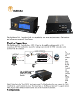
Introduction to the Microstepping MForce PowerDrive
The Microstepping MForce Pow-
erDrive is a high performance, low
cost microstepping driver that delivers
unsurpassed smoothness and perfor-
mance achieved through IMS’s advanced
2nd generation current control. By
applying innovative techniques to con-
trol current flow through the motor,
resonance is significantly dampened over
the entire speed range and audible noise is
reduced.
Microstepping MForce PowerDrives
accept a broad input voltage range
from +12 to +75 VDC, delivering enhanced
performance and speed. Oversized input
capacitors are used to minimize power line
surges, reducing problems that can occur
with long runs and multiple drive systems.
An extended operating range of –40° to +85°C provides long life, trouble free service in demanding environments.
The high, per phase output current of up to 5 Amps RMS, 7 Amps Peak, allows the extremely compact MForce
PowerDrive to control a broad array of motors from size 23 to size 42.
The microstepping drive accepts up to 20 resolution settings from full to 256 microsteps per full step, including:
degrees, metric and arc minutes. These settings may be changed on-the-fly or downloaded and stored in nonvolatile
memory with the use of a simple GUI which is provided. This eliminates the need for external switches or resistors.
Parameters are changed via an SPI port.
The versatile Microstepping MForce PowerDrive comes with dual mounting configurations to fit various system needs.
All interface connections are accomplished using pluggable locking wire crimp connectors. Optional cables are avail-
able for ease of connecting and configuring the MForce, and are recommended with first order.
The Microstepping
MForce PowerDrive
is a compact, powerful and inexpensive solution that will reduce system
cost, design and assembly time for a large range of applications.
Configuring
The IMS SPI Motor Interface software is an easy to install and use GUI for configuring the Microstepping MForce
PowerDrive from a computer's USB port. GUI access is via the IMS SPI Motor Interface included on the CD
shipped with the product, or from www.imshome.com. Optional cables are available for ease of connecting and
configuring the MForce.
The IMS SPI Motor Interface features:
Easy installation.
Automatic detection of MForce version
and communication conguration.
Will not set out-of-range values.
Tool-tips display valid range setting for each option.
Simple screen interfaces.
•
•
•
•
•
Figure 1.1.1: Microstepping MForce PowerDrive

1-6
Microstepping MForce PowerDrive Manual Revision R032008
Features and Benefits
High Performance Microstepping Driver
Advanced 2nd Generation Current Control for Exceptional Performance and Smoothness
Single Supply: +12 to +75 VDC
Low Cost
Extremely Compact
High Output Current:
Up to 5 Amps RMS, 7 Amps Peak (Per Phase)
20 Microstep Resolutions up to 51,200 Steps Per Rev Including:
Degrees, Metric, Arc Minutes
Optically Isolated Logic Inputs will Accept +5 to +24 VDC Signals, Sourcing or Sinking
Automatic Current Reduction
Configurable:
Motor Run/Hold Current
Motor Direction vs. Direction Input
Microstep Resolution
Clock Type: Step and Direction, Quadrature, Step Up and Step Down
Programmable Digital Filtering for Clock and Direction Inputs
Current and Microstep Resolution May Be Switched On-The-Fly
Dual Mounting Configurations
Power, Motor and Signal Interface via locking wire crimp style connectors.
Graphical User Interface (GUI) for Quick and Easy Parameter Setup
•
•
•
•
•
•
•
•
•
•
•
•
•
•
•
•
•
•
•

1-7
Part 1: Hardware Specifications
SE CT IO N 1. 2
Microstepping MForce PowerDrive Detailed Specifications
General Specifications
Electrical Specifications
Input Voltage (+V) Range* +12 to +75 VDC
Max Power Supply Current (Per MForce PowerDrive)* 4 Amps
Output Current RMS 5 Amps
Output Current Peak (Per Phase) 7 Amps
* Actual Power Supply Current will depend on Voltage and Load.
Table 1.2.1: Electrical Specifications
Thermal Specifications
Heat Sink Temperature -40°C to +85°C
Table 1.2.2: Thermal Specifications
I/O Specifications
Isolated Inputs — Step Clock, Direction and Enable
Resolution 10 Bit
Voltage Range (Sourcing or Sinking) +5 to +24 VDC
Current (+5 VDC Max) 8.7 mA
Current (+24 VDC Max) 14.6 mA
Table 1.2.3: I/O Specifications
Communications Specifications
Protocol SPI
Table 1.2.4: Communications Specifications
Motion Specifications
Microstep Resolution
Number of Resolutions 20
Available Microsteps Per Revolution
200 400 800 1000 1600 2000 3200 5000 6400 10000
12800 20000 25000 25600 40000 50000 51200 36000
1
21600
2
25400
3
1 = 0 . 0 1 d e g / µ s t e p 2 = 1 a r c m i n u t e / µ s t e p 3 = 0 . 0 0 1 m m / µ s t e p
Digital Filter Range
50 nS to 12.9 µS
(10 MHz to 38.8kHz)
Clock Types
Step/Direction,
Quadrature, Clock Up/
Clock Down
Step Frequency (Max) 5.0 MHz
Step Frequency Minimum Pulse Width 100 nS
Table 1.2.5: Motion Specifications

1-8
Microstepping MForce PowerDrive Manual Revision R032008
Mechanical Specifications - Dimensions in Inches (mm)
Figure 1.2.1: MForce PowerDrive
Mechanical Specifications
Microstepping MForce PowerDrive Setup Parameters
Name Function Range Units Default
MHC Motor Hold Current 0 to 100 percent 5
MRC Motor Run Current 1 to 100 percent 25
MSEL Microstep Resolution
1, 2, 4, 5, 8, 10, 16, 25, 32, 50,
64, 100,108, 125, 127,128,
180, 200, 250, 256
µsteps per
full step
256
DIR Motor Direction Override 0/1 – CW
HCDT Hold Current Delay Time 0 or 2-65535 mSec 500
CLK TYPE Clock Type
Step/Dir. Quadrature, Up/Down
(CW/CCW)
– Step/Dir
CLK IOF Clock and Direction Filter
50 nS to 12.9 µS
(10 MHz to 38.8kHz)
nS (MHz)
200nS(2.5
MHz)
USER ID User ID Customizable 1-3 characters IMS
WARN TEMP Warning Temperature 0 to +125 ºC 80
EN ACT Enable Active High/Low High or Low — High
PWM MSK PWM Mask 0 to 255 — 102
PWM PER PWM Duty Cycle 0 to 95 Percent 90%
PWM FREQ PWM Frequency Range 0 to 255 —
170 (20kHz to
60 kHz)
PWM CTL PWM Control See Section 2.4 See Section 2.4 0-10010
Table 1.2.6: Setup Parameters
Setup Parameters
The following table illustrates the setup parameters. These are easily configured using the IMS SPI Motor Interface
configuration utility. An optional Parameter Setup Cable is available and recommended with the first order.
3.473
(88.21)
2X 0.580
(2X 14.73)
Ø 0.187 ±0.01
(Ø 4.75 ±0.25)
2X #8 Screws
for End Mount
3.00 ±0.01
(76.2 ±0.25)
2.116
(53.75)
0.225
(5.72)
P4
P3
P1
3.473
(88.21)
Ø 0.160 ±0.01 Thru
(Ø 4.06 ±0.25 Thru)
4X #6 Screws
for Flat Mount
0.308 TYP.
(7.82 TYP.)
2.931 TYP.
(74.45 TYP.)
3.897
(98.98)
0.417 TYP.
(10.59 TYP.)
0.160 ±0.01
(4.06 ±0.25)
2.950
(74.93)

1-9
Part 1: Hardware Specifications
Pin Assignment and Description
P1 12-Pin Locking Wire Crimp Connector Option - Power, I/O and SPI
Communications
Pin Assignment - P1 Power, I/O and SPI
Connections
Pin # Function Description
Pin 1 N/C No Connect
Pin 2 N/C No Connect
Pin 3 Opto Reference
The Signal applied to the Optocoupler Reference will
determine the sinking/ or sourcing configuration of the inputs.
To set the inputs for sinking operation, a +5 to +24 VDC
supply is connected. If sourcing, the Reference is connected
to Ground.
Pin 4
Step Clock/Channel
A/ Clock Up
Step Clock input. The step clock input will receive the clock
pulses which will step the motor 1 step for each pulse. It
may also receive quadrature and clock up type inputs if so
configured.
Pin 5 Enable
Enable/Disable Input will enable or disable the driver output
to the motor. In the disconnected state the driver outputs are
enabled in either sinking or sourcing configuration.
Pin 6
Direction/Channel B/
Clock Down
Direction input. The axis direction will be with respect to the
state of the Direction Override Parameter. It may also receive
quadrature and clock up type inputs if so configured.
Pin 7 +5 VDC Output Supply voltage for the MD-CC300-000 Cable ONLY!
Pin 8 SPI Clock
The Clock is driven by the SPI Master. The clock cycles once
for each data bit.
Pin 9 GND Communications Ground.
Pin 10 MISO
Master-In/Slave-Out. Carries output data from the MFM back
to the SPI Master.
Pin 11 CS
SPI Chip Select. This signal is used to turn communications
on multiple MFM units on or off.
Pin 12 MOSI
Master-Out/Slave-In. Carries output data from the SPI Master
to the MFM.
Table 1.2.7: P1 Connector – Power, I/O and SPI Communications
NEED A CABLE?
The following cables
and converters are
available to interface
with P1:
12-Pin Locking Wire Crimp
PD12-1434-FL3
P3
P1
1 3 5 7 9 11
2 4 6 8 10 12
NEED A CABLE?
The following cables
and converters are
available to interface
communications with
USB to SPI:
MD-C300-000
10-Pin IDC to 12-Pin Locking
Wire Crimp Adapter
All SPI Communications will
connect to the P1 Connector.
An adapter is available to interface
the MD-CC300-000 to the 12-Pin
Locking Wire Crimp connector.
MD-ADP-1723C
This adapter may be used in
conjunction with the following
Prototype Development cables to
interface power and logic:
PD12-1434-FL3 (10')
ADP-3512-FL (12")
See Appendix A for details.
Figure 1.2.2: P1 — 12-Pin Locking Wire Crimp Pin Configuration
Recommended Connector Shell and Pins
Shell: AMP P/N 1-794617-2
Pins: 12 x AMP P/N 794610-1
Wire: 22 AWG Shielded Twisted Pair

1-10
Microstepping MForce PowerDrive Manual Revision R032008
P3 Connector - DC Power, 2-Pin Locking Wire Crimp
Pin Assignment - P3 Power
2-Pin Locking
Wire Crimp
Function Description
Pin 1 +V +12 to +75 VDC, 4 Amps Maximum per MDrive34Plus.
Pin 2 GND Power Supply Return.
Table 1.2.8: P3 Connector
P3
12 10 8 6 4 2
11 9 7 5 3 1
12
Figure 1.2.3: P3 — 2-Pin Locking Wire Crimp Pin Configuration
Pin Assignment - P4 Motor
5-Pin Locking
Wire Crimp
Function Description
Pin 1 Phase A Phase A Motor Output
Pin 2 Phase A Phase A Motor Return
Pin 3 Phase B Phase B Motor Output
Pin 4 Phase B Phase B Motor Return
Recommended
Cable
PD04-MF34-FL3
Table 1.2.9: P4 Connecter
P4 Connector - Motor
P4
12 10 8 6 4 2
11 9 7 5 3 1
1
1
2
2
3
4
Figure 1.2.4: P4 — 4-Pin Locking Wire Crimp Pin Configuration
Recommended Connector Shell and Pins
Shell: Molex P/N 39-01-2045
Pins: 4 x Molex P/N 44476-3112
Wire: 16 AWG Shielded Twisted Pair
Recommended Connector Shell and Pins
Shell: Molex P/N 510-67-0200
Pins: 2 x Molex P/N 502-17-9101
Wire: 18 AWG Shielded Twisted Pair
NEED A CABLE?
The following cables
and converters are
available to interface
with P3:
2-Pin Locking Wire Crimp
PD02-3400-FL3
WARNING! Do not
plug or unplug DC
Power with power
applied.
NEED A CABLE?
The following cables
and converters are
available to interface
with P4:
4-Pin Locking Wire Crimp
PD04-MF34-FL3

1-11
Part 1: Hardware Specifications
Options and Accessories
Parameter Setup Cable and Adapters
The optional 12.0' (3.6m) parameter setup cable part number MD-CC300-000 facilitates communications
wiring and is recommended with first order. It connects from the 10-Pin IDC Connector located at P2 to a
PC's USB port. If the12-pin pluggable locking wire crimp connector is used at P1, adapter MD-ADP-1723C
is required to use the MD-CC300-000.
USB to SPI ..........................................................................................................MD-CC300-000
Prototype Development Cable
To speed prototype development, these cables connect to user interface via flying leads with MForce mating
connector on opposite end.
Mating connector to 12-pin pluggable locking wire crimp plugs into MForce or adapter MD-ADP-1723C.
Choose from 2 lengths:
12.0" (30.5cm) ..........................................................................................................ADP-3512-FL
10.0' (3.0m) .......................................................................................................... PD12-1434-FL3
Mating connector to MForce 4-pin motor interface:
10.0' (3.0m). ....................................................................................................... PD04-MF17-FL3

1-12
Microstepping MForce PowerDrive Manual Revision R032008
Page Intentionally Left Blank
/