GOODMAN Commercial Heating and Cooling Gas Unit CPG SERIES User manual
- Category
- Heat pumps
- Type
- User manual

All information contained herein is subject to change without notice.
RECOGNIZE THIS SYMBOL AS A SAFETY PRECAUTION.
ATTENTION INSTALLING PERSONNEL
Prior to installation, thoroughly familiarize yourself with this Installation Manual. Observe all safety warnings.
During installation or repair, caution is to be observed.
It is your responsibility to install the product safely and to educate the customer on its safe use.
This Forced Air Central Unit Design Complies With
Requirements Embodied in The American National
Standard / National Standard of Canada Shown
Below.
ANSI Z21.47•CSA-2.3 Central Furnaces
C
US
®
I
NSTALLATION
I
NSTRUCTIONS
F
OR
C
OMMERCIAL
H
EATING
& C
OOLING
3 T
ON
- 6 T
ON
P
ACKAGE
G
AS
U
NIT
CPG S
ERIES
Goodman Manufacturing Company, L.P.
IO-353C 5151 Felipe, Suite 500, Houston, TX 77056
11/10 www.goodmanmfg.com www.amana-hac.com
© 2009-2010 Goodman Manufacturing Company, L.P.

2
REPLACEMENT PARTS
ORDERING PARTS
When reporting shortages or damages, or ordering repair
parts, give the complete unit model and serial numbers
as stamped on the unit’s nameplate.
Replacement parts for this appliance are available
through your contractor or local distributor. For the
location of your nearest distributor, consult the white
business pages, the yellow page section of the local
telephone book or contact:
CONSUMER AFFAIRS
GOODMAN MANUFACTURING COMPANY, L.P.
7401 SECURITY WAY
HOUSTON, TEXAS 77040
(877) 254-4729
SAFETY INSTRUCTIONS
TO THE INSTALLER
Before installing this unit, please read this manual to
familiarize yourself on the specific items which must be
adhered to, including maximum external static pressure
to unit, air temperature rise, minimum or maximum CFM
and motor speed connections.
Keep this literature in a safe place for future reference.
I
F
THE
INFORMATION
IN
THESE
INSTRUCTIONS
IS
NOT
FOLLOWED
EXACTLY
,
A
FIRE
OR
EXPLOSION
MAY
RESULT
CAUSING
PROPERTY
DAMAGE
,
PERSONAL
INJURY
OR
LOSS
OF
LIFE
.
- D
O
NOT
STORE
OR
USE
GASOLINE
OR
OTHER
FLAMMABLE
VAPORS
AND
LIQUIDS
IN
THE
VICINITY
OF
THIS
OR
ANY
OTHER
APPLIANCE
.
- WHAT TO DO IF YOU SMELL GAS:
* D
O
NOT
TRY
TO
LIGHT
ANY
APPLIANCE
.
* D
O
NOT
TOUCH
ANY
ELECTRICAL
SWITCH
;
DO
NOT
USE
ANY
PHONE
IN
YOUR
BUILDING
.
* I
MMEDIATELY
CALL
YOUR
GAS
SUPPLIER
FROM
A
NEIGHBORS
PHONE
. F
OLLOW
THE
GAS
SUPPLIERS
INSTRUCTIONS
.
* I
F
YOU
CANNOT
REACH
YOUR
GAS
SUPPLIER
,
CALL
THE
FIRE
DEPARTMENT
.
- I
NSTALLATION
AND
SERVICE
MUST
BE
PERFORMED
BY
A
QUALIFIED
INSTALLER
,
SERVICE
AGENCY
OR
THE
GAS
SUPPLIER
WARNING
WARNING
SHOULD OVERHEATING OCCUR OR THE GAS SUPPLY FAIL TO SHUT OFF, TURN
OFF THE MANUAL GAS SHUTOFF VALVE EXTERNAL TO THE FURNACE BEFORE
TURNING OFF THE ELECTRICAL SUPPLY.
S
HEET
METAL
PARTS
,
SCREWS
,
CLIPS
AND
SIMILAR
ITEMS
INHERENTLY
HAVE
SHARP
EDGES
,
AND
IT
IS
NECESSARY
THAT
THE
INSTALLER
AND
SERVICE
PERSONNEL
EXERCISE
CAUTION
.
CAUTION
Index
Replacement Parts ........................................................2
Safety Instructions ........................................................2
General Information ......................................................3
Unit Location .................................................................4
Clearances .....................................................................5
Roof Curb Post-Installation Checks ............................6
Roof Top Duct Connections .........................................6
Rigging Details ..............................................................7
Electrical Wiring ............................................................9
Gas Supply Piping.......................................................10
Propane Gas Installations ..........................................12
Circulating Air and Filters...........................................13
Venting .........................................................................13
Condensate Drain Connection ...................................13
Startup, Adjustments, and Checks ............................14
Normal Sequence Of Operation .................................19
Troubleshooting ..........................................................20
Input Rating .................................................................21
Air flow Adjustments...................................................22
Motor Sheave Adjustments ........................................22
Maintenance ................................................................22
Appendix A Blower Performance Tables...................25
Direct Drive ..............................................................25
CPG036 Down Shot and Horizontal ...................25
CPG048 Down Shot and Horizontal ...................26
CPG060 Down Shot.............................................27
CPG060 Horizontal ..............................................28
Belt Drive .................................................................29
Standard Down Shot ...........................................29
Standard Horizontal ............................................30
High Static Down Shot........................................31
Belt Drive - High Static Horizontal .....................32
Appendix B Electrical Data.........................................33
Appendix C Unit Dimensions .....................................34
Appendix D Wiring Diagrams .....................................35

3
D
O
NOT
CONNECT
TO
OR
USE
ANY
DEVICE
THAT
IS
NOT
DESIGN
CERTIFIED
BY
G
OODMAN
FOR
USE
WITH
THIS
UNIT
. S
ERIOUS
PROPERTY
DAMAGE
,
PERSONAL
INJURY
,
REDUCED
UNIT
PERFORMANCE
AND
/OR
HAZARDOUS
CONDITIONS
MAY
RESULT
FROM
THE
USE
OF
SUCH
NON
-
APPROVED
DEVICES
.
WARNING
WARNING
T
HIS PRODUCT CONTAINS OR PRODUCES A CHEMICAL OR CHEMICALS WHICH
MAY CAUSE SERIOUS ILLNESS OR DEATH AND WHICH ARE KNOWN TO THE
S
TATE OF
C
ALIFORNIA TO CAUSE CANCER, BIRTH DEFECTS OR OTHER
REPRODUCTIVE HARM.
WARNING
T
O AVOID PROPERTY DAMAGE, PERSONAL INJURY OR DEATH, DO NOT USE
THIS UNIT IF ANY PART HAS BEEN UNDER WATER.
I
MMEDIATELY CALL A
QUALIFIED SERVICE TECHNICIAN TO INSPECT THE FURNACE AND TO REPLACE
ANY PART OF THE CONTROL SYSTEM AND ANY GAS CONTROL HAVING BEEN
UNDER WATER.
T
HIS
UNIT
MUST
NOT
BE
USED
AS
A
"
CONSTRUCTION
HEATER
"
DURING
THE
FINISHING
PHASES
OF
CONSTRUCTION
ON
A
NEW
STRUCTURE
. T
HIS
TYPE
OF
USE
MAY
RESULT
IN
PREMATURE
FAILURE
OF
THE
UNIT
DUE
TO
EXTREMELY
LOW
RETURN
AIR
TEMPERATURE
AND
EXPOSURE
TO
CORROSIVE
OR
VERY
DIRTY
ATMOSPHERES
.
HIGH VOLTAGE!
D
ISCONNECT
ALL
POWER
BEFORE
SERVICING
OR
INSTALLING
THIS
UNIT
. M
ULTIPLE
POWER
SOURCES
MAY
BE
PRESENT
. F
AILURE
TO
DO
SO
MAY
CAUSE
PROPERTY
DAMAGE
,
PERSONAL
INJURY
OR
DEATH
.
WARNING
WARNING
TO PREVENT THE RISK OF PROPERTY DAMAGE, PERSONAL INJURY, OR DEATH,
DO NOT STORE COMBUSTIBLE MATERIALS OR USE GASOLINE OR OTHER
FLAMMABLE LIQUIDS OR VAPORS IN THE VICINITY OF THIS APPLIANCE.
WARNING
HIGH VOLTAGE!
INSTALLATION
AND
REPAIR
OF
THIS
UNIT
SHOULD
BE
PERFORMED
ONLY
BY
INDIVIDUALS
MEETING
THE
REQUIREMENTS
OF
AN
“E
NTRY
L
EVEL
T
ECHNICIAN
”
AS
SPECIFIED
BY
THE
A
IR
C
ONDITIONING
AND
R
EFRIGERATION
I
NSTITUTE
(ARI). A
TTEMPTING
TO
INSTALL
OR
REPAIR
THIS
UNIT
WITHOUT
SUCH
BACKGROUND
MAY
RESULT
IN
PRODUCT
DAMAGE
,
PERSONAL
INJURY
OR
DEATH
.
-
CARBON MONOXIDE POISONING
HAZARD
RISQUE D'EMPOISONNEMENT AU
MONOXYDE DE CARBONE
FAILURE TO KEEP THIS COMPARTMENT CLOSED
EXCEPT WHEN SERVICING COULD RESULT IN
CARBON MONOXIDE POISONING OR DEATH.
THIS COMPARMENT MUST BE CLOSED EXCEPT
WHEN SERVICING
SI CE COMPARTMENT N'EST PAS FERME EN
TOUT TEMPS, SAUF EN CAS DE REPARATION, IL Y
A RISQUE D'EMPOISONNEMENT OU MONOXYDE
DE CARBONE OU DE MORT.
CE COMPARTIMENT DOIT ETRE FERME SAUF AU
MOMENT DE L'ENTRETIEN.
WARNING
AVERTISSEMENT
ADVERTENCIA
0140L00106
PELIGRO MONOXIDO DE CARBONO
TOXICO
EL FRACASO DE NO MANTENER
COMPARTIMIENTO CERRADO MENOS DURANTE,
ATENDER, PODRIA TENER COMO RESULTADO
ENVENENAR DE MONOXIDO DE CARBONO O
MUERTE.
ESTE COMPARTIMIENTO DEBE CERRADO MENOS
AL ATENDER
GENERAL INFORMATION
WARNING
T
O PREVENT PROPERTY DAMAGE, PERSONAL INJURY OR DEATH, DUE TO FIRE,
EXPLOSIONS, SMOKE, SOOT, CONDENSATION, ELECTRIC SHOCK OR CARBON
MONOXIDE, THIS UNIT MUST BE PROPERLY INSTALLED, REPAIRED, OPERATED,
AND MAINTAINED.
This unit is approved for outdoor installation ONLY. To
assure that your unit operates safely and efficiently, it must
be installed, operated, and maintained in accordance with
these installation and operating instructions, all local building
codes and ordinances, or in their absence, with the latest
edition of the National Fuel Gas Code NFPA54/ANSI Z223.1
and National Standard of Canada CAN/CSA B149 Installa-
tion Codes.
The heating and cooling capacities of the unit should be
greater than or equal to the design heating and cooling loads
of the area to be conditioned. The loads should be calculated
by an approved method or in accordance with ASHRAE Guide
or Manual J - Load Calculations published by the Air Condi-
tioning Contractors of America.
Obtain from:
American National Standards Institute
1430 Broadway
New York, NY 10018
System design and installation should also, where applicable,
follow information presented in accepted industry guides such
as the ASHRAE Handbooks. The manufacturer assumes no

4
responsibility for equipment installed in violation of any code
or regulation. The mechanical installation of the packaged
roof top units consists of making final connections between
the unit and building services; supply and return duct con-
nections; and drain connections (if required). The internal
systems of the unit are completely factory-installed and tested
prior to shipment.
Units are generally installed on a steel roof mounting curb
assembly which has been shipped to the job site for installa-
tion on the roof structure prior to the arrival of the unit. The
model number shown on the unit’s identification plate identi-
fies the various components of the unit such as refrigeration
tonnage, heating input and voltage.
Carefully inspect the unit for damage including damage to
the cabinetry. Any bolts or screws which may have loosened
in transit must be re-tightened. In the event of damage, the
receiver should:
1. Make notation on delivery receipt of any visible
damage to shipment or container.
2. Notify carrier promptly and request an inspection.
3. In case of concealed damage, carrier should be
notified as soon as possible-preferably within 5 days.
4. File the claim with the following supporting documents:
a. Original Bill of Lading, certified copy, or indemnity
bond.
b. Original paid freight bill or indemnity in lieu thereof.
c. Original invoice or certified copy thereof, showing
trade and other discounts or reductions.
d. Copy of the inspection report issued by carrier
representative at the time damage is reported to the
carrier. The carrier is responsible for making prompt
inspection of damage and for a thorough
investigation of each claim. The distributor or
manufacturer will not accept claims from dealers for
transportation damage.
NOTE: When inspecting the unit for transportation damage,
remove all packaging materials. Recycle or dispose of the
packaging material according to local codes.
PRE-INSTALLATION CHECKS
Carefully read all instructions for the installation prior to in-
stalling unit. Ensure each step or procedure is understood
and any special considerations are taken into account be-
fore starting installation. Assemble all tools, hardware and
supplies needed to complete the installation. Some items may
need to be purchased locally.
UNIT LOCATION
WARNING
T
O PREVENT POSSIBLE EQUIPMENT DAMAGE, PROPERTY DAMAGE, PERSONAL
INJURY OR DEATH, THE FOLLOWING BULLET POINTS MUST BE OBSERVED
WHEN INSTALLING THE UNIT.
IMPORTANT NOTE: Remove wood shipping rails prior to
installation of the unit.
ALL INSTALLATIONS:
NOTE: Appliance is shipped from factory for vertical duct
application.
Proper installation of the unit ensures trouble-free operation.
Improper installation can result in problems ranging from
noisy operation to property or equipment damages, danger-
ous conditions that could result in injury or personal property
damage and could void the warranty. Give this booklet to the
user and explain it’s provisions. The user should retain these
instructions for future reference.
• For proper flame pattern within the heat exchanger
and proper condensate drainage, the unit must be
mounted level.
• The flue outlet must be at least 12 inches from any
opening through which flue gases could enter a
building, and at least three feet above any forced air
inlet located within ten feet. The economizer/manual
fresh air intake/motorized fresh air intake and
combustion air inlet mounted on the unit are not
affected by this restriction.
• To avoid possible corrosion of the heat exchanger,
do not locate the unit in an area where the outdoor air
(i.e. combustion air for the unit) will be frequently
contaminated by compounds containing chlorine or
fluorine. Common sources of such compounds include
swimming pool chemicals and chlorine bleaches, paint
stripper, adhesives, paints, varnishes, sealers, waxes
(which are not yet dried) and solvents used during
construction and remodeling. Various commercial and
industrial processes may also be sources of chlorine/
fluorine compounds.
• To avoid possible illness or death of the building
occupants, do NOT locate outside air intake device
(economizer, manual fresh air intake, motorized fresh
air intake) too close to an exhaust outlet, gas vent
termination, or plumbing vent outlet. For specific
distances required, consult local codes.
• Allow minimum clearances from the enclosure for fire
protection, proper operation, and service access (see
unit clearances). These clearances must be
permanently maintained.
• The combustion air inlet and flue outlet on the unit
must never be obstructed. If used, do not allow the
economizer/manual fresh air damper/ motorized fresh
air damper to become blocked by snow or debris. In
some climates or locations, it may be necessary to
elevate the unit to avoid these problems.
• When the unit is heating, the temperature of the return
air entering the unit must be between 50° F and 100°
F.
GROUND LEVEL INSTALLATIONS ONLY:
• When the unit is installed on the ground adjacent to
the building, a level concrete (or equal) base is
recommended. Prepare a base that is 3” larger than
the package unit footprint and a minimum of 3” thick.

5
• The base should also be located where no runoff of
water from higher ground can collect in the unit.
ROOF TOP INSTALLATIONS ONLY:
• To avoid possible property damage or personal injury,
the roof must have sufficient structural strength to carry
the weight of the unit(s) and snow or water loads as
required by local codes. Consult a structural engineer
to determine the weight capabilities of the roof.
• The unit may be installed directly on wood floors or
on Class A, Class B, or Class C roof covering material.
• To avoid possible personal injury, a safe, flat surface
for service personnel should be provided.
• As indicated on the unit data plate, a minimum
clearance of 36” to any combustible material is
required on the furnance access side of the unit. All
combustible materials must be kept out of this area.
• This 36” clearance must also be maintained to insure
proper combustion air and flue gas flow. The
combustion air intake and furance flue discharge must
not be blocked for any reason, including blockage by
snow.
• Adequate clearances from the furnace flue discharge
to any adjacent public walkways, adjacent buildings,
building openings or openable windows must be
maintained in accordance with the latest edition of
the National Fuel Gas Code (ANSI Z223.1)
• Minimum horizontal clearance of 48” from the furnace
flue discharge to any electric meters, gas meters,
regulators and relief equipment is required.
UNIT PRECAUTIONS
• Do not stand or walk on the unit.
• Do not drill holes anywhere in panels or in the base
frame of the unit. Unit access panels provide
structural support.
• Do not remove any access panels until unit has been
installed on roof curb or field supplied structure.
• Do not roll unit across finished roof without prior
approval of owner or achitect.
• Do not skid or slide on any surface as this may
damage unit base. The unit must be stored on a
flat, level surface. Protect the condenser coil
because it is easily damaged.
ROOF CURB INSTALLATIONS ONLY:
Curb installatons must comply with local codes and should
be done in accordance with the established guidelines of the
National Roofing Contractors Association.
Proper unit installation requires that the roof curb be firmly
and permanently attached to the roof structure. Check for
adequate fastening method prior to setting the unit on the
curb.
Full perimeter roof curbs are available from the factory and
are shipped unassembled. Field assembly, squaring, level-
ing and mounting on the roof structure are the responsibility
of the installing contractor. All required hardware necessary
for the assembly of the sheet metal curb is included in the
curb accessory.
WARNING
T
O PREVENT POSSIBLE EQUIPMENT DAMAGE, PROPERTY DAMAGE, PERSONAL
INJURY OR DEATH, THE FOLLOWING BULLET POINTS MUST BE OBSERVED
WHEN INSTALLING THE UNIT.
• Sufficient structural support must be determined prior
to locating and mounting the curb and package unit.
• Ductwork must be constructed using industry
guidelines. The duct work must be placed into the
roof curb before mounting the package unit. Our full
perimeter curbs include duct connection frames to be
assembled with the curb. Cantilevered type curbs
are not available from the factory.
• Curb insulation, cant strips, flashing and general
roofing material are furnished by the contractor.
The curbs must be supported on parallel sides by roof mem-
bers. The roof members must not penetrate supply and re-
turn duct opening areas as damage to the unit might occur.
NOTE: The unit and curb accessories are designed to allow
vertical duct installation before unit placement. Duct
installaton after unit placement is not recommended.
A
LL
CURBS
LOOK
SIMILAR
. T
O
AVOID
INCORRECT
CURB
POSITIONING
,
CHECK
JOB
PLANS
CAREFULLY
AND
VERIFY
MARKINGS
ON
CURB
ASSEMBLY
. I
NSTRUCTIONS
MAY
VARY
IN
CURB
STYLES
AND
SUPERSEDES
INFORMATION
SHOWN
.
CAUTION
See the manual shipped with the roof curb for assembly and
installation instructions.
CLEARANCES
48”
75”
48”
Unit Clearances

6
Adequate clearance around the unit should be kept for safety,
service, maintenance, and proper unit operation. A total clear-
ance of 75” on the main control panel side of the unit is rec-
ommended to facilitate possible fan shaft, coil, electric heat
and gas furnace removal. A clearance of 48” is recommended
on all other sides of the unit to facilitate possible compressor
removal, to allow service access and to insure proper venti-
lation and condenser airflow. The unit must not be installed
beneath any obstruction. The unit should be installed re-
mote from all building exhausts to inhibit ingestion of exhaust
air into the unit fresh air intake.
INSULATED
PANELS
Roof Curb Installation
ROOF CURB POST-INSTALLATION CHECKS
After installation, check the top of the curb, duct connection
frame and duct flanges to make sure gasket has been ap-
plied properly. Gasket should be firmly applied to the top of
the curb perimeter, duct flanges and any exposed duct con-
nection frame. If gasket is loose, re-apply using strong
weather resistant adhesive.
PROTRUSION
Inspect curb to ensure that none of the utility services (elec-
tric) routed through the curb protrude above the curb.
I
F
PROTRUSIONS
EXIST
,
DO
NO
ATTEMPT
TO
SET
UNIT
ON
CURB
.
CAUTION
ROOF TOP DUCT CONNECTIONS
Install all duct connections on the unit before placing the unit
on rooftop.
HORIZONTAL DISCHARGE
For horizontal discharge, remove the supply and return duct
covers and place them over the vertical discharge return and
supply openings. Install with insulation facing up, using the
longer screws provided in the literature package.
Ensure that the top of the duct connection frame is flush with
the top of the roof curb.
Flexible duct connectors between the unit and ducts are rec-
ommended. Insulate and weatherproof all external ductwork
and joints as required and in accordance with local codes.
SUPPLY
12”
17” 7 3/8”
11” 4 7/8””
25”
6 3/16”
REMOVE
COVERS
Horizontal Discharge Duct Connections

7
RIGGING DETAILS
WARNING
T
O PREVENT PROPERTY DAMAGE, THE UNIT SHOULD REMAIN IN AN UPRIGHT
POSITION DURING ALL RIGGING AND MOVING OPERATIONS.
T
O FACILITATE
LIFTING AND MOVING WHEN A CRANE IS USED, PLACE THE UNIT IN AN
ADEQUATE CABLE SLING.
I
F
UNITS
ARE
LIFTED
TWO
AT
A
TIME
,
THE
FORK
HOLES
ON
THE
CONDENSER
END
OF
THE
UNIT
MUST
NOT
BE
USED
. M
INIMUM
FORK
LENGTH
IS
42”
TO
PREVENT
DAMAGE
TO
THE
UNIT
;
HOWEVER
, 48”
IS
RECOMMENDED
.
CAUTION
Provisions for forks have been included in the unit base frame. No other fork locations are approved.
WARNING
T
O PREVENT POSSIBLE EQUIPMENT DAMAGE, PROPERTY DAMAGE, PERSONAL
INJURY OR DEATH, THE FOLLOWING BULLET POINTS MUST BE OBSERVED
WHEN INSTALLING THE UNIT.
• Unit must be lifted by the four lifting holes located at the base frame corners.
• Lifting cables should be attached to the unit with shackles.
• The distance between the crane hook and the top of the unit must not be less than 60”.
• Two spreader bars must span over the unit to prevent damage to the cabinet by the lift cables. Spreader bars must
be of sufficient length so that cables do not come in contact with the unit during transport. Remove wood struts
mounted beneath unit base frame before setting unit on roof curb. These struts are intended to protect unit base
frame from fork lift damage. Removal is accomplished by extracting the sheet metal retainers and pulling the struts
through the base of the unit. Refer to rigging label on the unit.
Important: If using bottom discharge with roof curb, ductwork should be attached to the curb prior to installing the unit.
Ductwork dimensions are shown in Roof Curb Installation Instructions.
Refer to the Roof Curb Installation Instructions for proper curb installation. Curbing must be installed in compliance with the
National Roofing Contractors Association Manual.
Lower unit carefully onto roof mounting curb. While rigging unit, center of gravity will cause condenser end to be lower than
supply air end.
To assist in determining rigging requirements, unit weights are shown as follows:

8
A
B
C
D
CG
SUPPLY
RETURN
EVAPORATOR COIL
CONDENSER
COIL
COMPRESSOR
Y
X
Corner & Center of Gravity Locations
ABCD
CPG036045* 37 30 550 525 100 165 100 165
CPG036090* 37 30 560 535 100 170 100 170
CPG048090* 37 30 600 575 110 180 110 180
CPG048115* 37 30 605 580 110 180 110 180
CPG060090* 37 30 645 620 115 190 120 195
CPG060140* 37 30 655 630 120 195 120 195
CPG072140* 37 30 715 690 130 215 130 215
Operating
Weight
(lbs)
Corner Weights ( lbs )
* Weights shown are belt drive with no accessories.
Model
X
(in)
Y
(in)
Shipping
Weight
(lbs)
T
O
PREVENT
SEVERE
DAMAGE
TO
THE
BOTTOM
OF
THE
UNIT
,
DO
NOT
FORK
LIFT
UNIT
AFTER
WOOD
STRUTS
HAVE
BEEN
REMOVED
.
CAUTION
Bring condenser end of unit into alignment with the curb. With condenser end of the unit resting on curb member and using
curb as a fulcrum, lower opposite end of the unit until entire unit is seated on the curb. When a rectangular cantilever curb
is used, care should be taken to center the unit. Check for proper alignment and orientation of supply and return openings
with duct.
RIGGING REMOVAL
T
O
PREVENT
DAMAGE
TO
THE
UNIT
,
DO
NOT
ALLOW
CRANE
HOOKS
AND
SPREADER
BARS
TO
REST
ON
THE
ROOF
OF
THE
UNIT
.
CAUTION
Remove spreader bars, lifting cables and other rigging equipment.

9
ELECTRICAL WIRING
HIGH VOLTAGE!
D
ISCONNECT
ALL
POWER
BEFORE
SERVICING
OR
INSTALLING
THIS
UNIT
. M
ULTIPLE
POWER
SOURCES
MAY
BE
PRESENT
. F
AILURE
TO
DO
SO
MAY
CAUSE
PROPERTY
DAMAGE
,
PERSONAL
INJURY
OR
DEATH
.
WARNING
HIGH VOLTAGE!
T
O
AVOID
PERSONAL
INJURY
OR
DEATH
DUE
TO
ELECTRICAL
SHOCK
,
DO
NOT
TAMPER
WITH
FACTORY
WIRING
. T
HE
INTERNAL
POWER
AND
CONTROL
WIRING
OF
THESE
UNITS
ARE
FACTORY
-
INSTALLED
AND
HAVE
BEEN
THOROUGHLY
TESTED
PRIOR
TO
SHIPMENT
.
C
ONTACT
YOUR
LOCAL
REPRESENTATIVE
IF
ASSISTANCE
IS
REQUIRED
.
WARNING
T
O
PREVENT
DAMAGE
TO
THE
WIRING
,
PROTECT
WIRING
FROM
SHARP
EDGES
. F
OLLOW
NATIONAL
ELECTRICAL
CODE
AND
ALL
LOCAL
CODES
AND
ORDINANCES
. D
O
NOT
ROUTE
WIRES
THROUGH
REMOVABLE
ACCESS
PANELS
.
CAUTION
C
ONDUIT
AND
FITTINGS
MUST
BE
WEATHER
-
TIGHT
TO
PREVENT
WATER
ENTRY
INTO
THE
BUILDING
.
CAUTION
For unit protection, use a fuse or HACR circuit breaker that is
in excess of the circuit ampacity, but less than or equal to the
maximum overcurrent protection device. DO NOT EXCEED
THE MAXIMUM OVERCURRENT DEVICE SIZE SHOWN
ON UNIT DATA PLATE.
All line voltage connections must be made through weather-
proof fittings. All exterior power supply and ground wiring
must be in approved weatherproof conduit.
The main power supply wiring to the unit and low voltage
wiring to accessory controls must be done in accordance with
these instructions, the latest edition of the National Electriacl
Code (ANSI/NFPA 70), and all local codes and ordinances.
All field wiring shall conform with the temperature limitations
for Type T wire (63°F/35°C rise).
The main power supply for the CPG036XXX3,4,7 through
CPG072 shall be three-phase, three wire. The power sup-
ply for the CPG036XXX1 through CPG060 shall be single-
phase, two wire. The unit is factory wired for the voltage shown
on the unit’s data plate.
NOTE: If supply voltage is 208V, lead on primary of trans-
former TRANS1 must be moved from the 230V to the 208V
tap.
Main power wiring should be sized for the minimum wire
ampacity shown on the unit’s database. Size wires in accor-
dance with the ampacity tables in Article 310 of the National
Electrical Code. If long wires are required, it may be neces-
sary to increase the wire size to prevent excessive voltage
drop. Wires should be sized for a maximum of 3% voltage
drop.
CAUTION
T
O AVOID PROPERTY DAMAGE OR PERSONAL INJURY DUE TO FIRE, USE
ONLY COPPER CONDUCTORS.
CAUTION
T
O PREVENT IMPROPER AND DANGEROUS OPERATION DUE TO WIRING ERRORS,
LABEL ALL WIRES PRIOR TO DISCONNECTION WHEN SERVICING CONTROLS.
V
ERIFY PROPER OPERATION AFTER SERVICING.
NOTE: A weather-tight disconnect switch, properly sized for
the unit total load, must be field installed. An external field
supplied disconnect may be mounted on the exterior panel.
Ensure the data plate is not covered by the field-supplied
disconnect switch.
• Some disconnect switches are not fused. Protect the
power leads at the point of distribution in accordance
with the unit data plate.
• The unit must be electrically grounded in accordance
with local codes or, in the absence of local codes,
with the latest edition of the National Electrical Code
(ANSI-NFPA 70). A ground lug is provided for this
purpose. Size grounding conductor in accordance
with Table 250-95 of the National Electrical Code. Do
not use the ground lug for connecting a neutral
conductor.
• Connect power wiring to the compressor contactor
closest to the entrance located within the main control
box.
LOW VOLTAGE
BLOCK
MAIN POWER
LOW VOLTAGE
ENTRANCE
POWER THRU
THE CURB
Power and Low Voltage Block Connections
F
AILURE
OF
UNIT
DUE
TO
OPERATION
ON
IMPROPER
LINE
VOLTAGE
OR
WITH
EXCESSIVE
PHASE
UNBALANCE
CONSTITUTES
PRODUCT
ABUSE
AND
WILL
VOID
YOUR
WARRANTY
AND
MAY
CAUSE
SEVERE
DAMAGE
TO
THE
UNIT
ELECTRICAL
COMPONENTS
.
WARNING

10
Areas Without Convenience Outlet
It is recommended that an independant 115V power source
be brought to the vicinity of the roof top unit for portable lights
and tools used by the service mechanic.
UNITS INSTALLED ON ROOF TOPS
Main power and low voltage wiring may enter the unit through
the condenser end of unit or through the roof curb. Install
conduit connectors at the desired entrance locations. Exter-
nal connectors must be weatherproof. All holes in the unit
base must be sealed (including those around conduit nuts)
to prevent water leakage into building. All required conduit
and fittings are to be field supplied.
Supply voltage to roof top unit must not vary by more than
10% of the value indicated on the unit data plate. Phase
voltage unbalance must not exceed 2%. Contact your local
power company for correction of improper voltage or phase
unbalance.
HIGH VOLTAGE ENTRANCE
LOW VOLTAGE ENTRANCE
1:4
30 1/4”*
12 3/8”
(REMOVE PLUG)
* (6 Ton - 34 1/4”)
4 1/2”
47 1/2”
7 1/2”
POWER THRU
THE CURB
3.5 DIA.
Electrical Entrance and Thru Curb
Unit is equipped with a Low Voltage Terminal Block and has
Single Point wiring to the contactor.
LOW VOLTAGE CONTROL WIRING
1. A 24V thermostat must be installed for unit operation.
It may be purchased with the unit or field -supplied.
Thermostats may be programmable or
electromechanical as required.
2. Locate thermostat or remote sensor in the conditioned
space where it will sense average temperature. Do
not locate the device where it may be directly exposed
to supply air, sunlight or other sources of heat. Follow
installation instructions packaged with the thermostat.
3. Use #18 AWG wire for 24V control wiring runs not
exceeding 75 feet. Use #16 AWG wire for 24V control
wiring runs not exceeding 125 feet. Use #14 AWG
wire for 24V control wiring runs not exceeding 200
feet. Low voltage wiring may be National Electrical
Code (NEC) Class 2 where permitted by local codes.
4. Route thermostat wires from sub-base terminals to
the unit. Control wiring should enter through the
condenser end of unit or through curb. Connect
thermostat and any accessory wiring to low voltage
terminal block TB1 in the main control box.
NOTE: Field-supplied conduit may need to be installed
depending on unit/curb configuration. Use #18 AWG solid
conductor wire whenever connecting thermostat wires to
terminals on sub-base. DO NOT use larger than #18 AWG
wire. A transition to #18 AWG wire may be required before
entering thermostat sub-base.
LEAD THERMOSTAT
Red R (24V)
Green G (Fan)
Yellow Y1 (High Cool)
Purple Y2 (Low Cool)
Blue Common (if req'd)
White W1 (Heat)
Brown W2
(
Hi
g
h Heat
)
CPG 036 Thru 072 (Gas Heat)
GAS SUPPLY PIPING
T
O
PREVENT
PERSONAL
INJURY
OR
DEATH
DUE
TO
IMPROPER
INSTALLATION
,
ADJUSTMENT
,
ALTERATION
,
SERVICE
OR
MAINTENANCE
,
REFER
TO
THIS
MANUAL
. F
OR
ADDITIONAL
ASSISTANCE
OR
INFORMATION
,
CONSULT
A
QUALIFIED
INSTALLER
,
SERVICE
AGENCY
OR
THE
GAS
SUPPLIER
.
WARNING
IMPORTANT NOTE: This unit is factory set to operate on
natural gas at the altitudes shown on the rating plate.
T
O
AVOID
PROPERTY
DAMAGE
,
PERSONAL
INJURY
OR
DEATH
WHEN
EITHER
USING
PROPANE
GAS
ALONE
OR
AT
HIGHER
ALTITUDES
,
OBTAIN
AND
INSTALL
THE
PROPER
CONVERSION
KIT
(
S
). F
AILURE
TO
DO
SO
CAN
RESULT
IN
UNSATISFACTORY
OPERATION
AND
/
OR
EQUIPMENT
DAMAGE
. H
IGH
ALTITUDE
KITS
ARE
FOR
U.S.
I
NSTALLATIONS
ONLY
AND
ARE
NOT
APPROVED
FOR
USE
IN
C
ANADA
.
WARNING
The rating plate is stamped with the model number, type of
gas and gas input rating. Make sure the unit is equipped to
operate on the type of gas available. Conversion to propane

11
(LP) gas is permitted with the use of the factory authorized
conversion kit (see the unit Technical Manual for the appro-
priate kit). For High Altitude derates, refer to the latest edition
of the National Fuel Gas Code NFPA 54/ANSI Z223.1.
NATURAL
Min. 5.0" W.C., Max. 10.0" W.C.
PROPANE
Min. 11.0" W.C., Max. 14.0" W.C.
INLET GAS PRESSURE
IInlet Gas Pressure Must Not Exceed the Maximum Value Shown in Table
Above.
The minimum supply pressure should not vary from that
shown in the table above because this could prevent the unit
from having dependable ignition. In addition, gas input to the
burners must not exceed the rated input shown on the rating
plate. Overfiring of the unit could result in premature heat
exchanger failure.
PIPING
IMPORTANT NOTE: To avoid possible unsatisfactory opera-
tion or equipment damage due to under firing of equipment,
do not undersize the natural/propane gas piping from the
meter/tank to the unit. When sizing a trunk line, include all
appliances on that line that could be operated simultaneously.
The rating plate is stamped with the model number, type of
gas and gas input rating. Make sure the unit is equipped to
operate on the type of gas available. The gas line installation
must comply with local codes, or in the absence of local codes,
with the latest edition of the National Fuel Gas Code NFPA
54/ANSI Z223.1.
Natural Gas Connection
Len
g
th of
Pipe in Feet
1/2 3/4
1
1 1/4 1 1/2
10 132 278 520 1050 1600
20 92 190 350 730 1100
30 73 152 285 590 980
40 63 130 245 500 760
50 56 115 215 440 670
60 50 105 195 400 610
70 46 96 180 370 560
80 43 90 170 350 530
90 40 84 160 320 490
100 38 79 150 305 460
Pressure = .50 PSIG or less and Pressure Drop of 0.3" W.C. (Based
on 0.60 S
p
ecific Gravit
y
Gas
)
Natural Gas Capacity of Pipe
in Cubic Feet of Gas Per Hour (CFH)
Nominal Black Pipe Size (inches)
BTUH Furnace Input
Heatin
g
Value of Gas
(
BTU/Cubic Foot
)
CFH =
Refer to the Proper Piping Practice drawing for the general
layout at the unit. The following rules apply:
1. Use black iron pipe and fittings for the supply piping.
The use of a flex connector and/or copper piping is
permitted as long as it is in agreement with local
codes.
2. Use pipe joint compound on male threads only. Pipe
joint compound must be resistant to the action of the
fuel used.
3. Use ground joint unions.
4. Install a drip leg to trap dirt and moisture before it can
enter the gas valve. The drip leg must be a minimum
of three inches long.
5. Use two pipe wrenches when making connection to
the gas valve to keep it from turning.
6. Install a manual shut-off valve in a convenient location
(within six feet of unit) between the meter and the
unit.
7. Tighten all joints securely.
8. The unit must be connected to the building piping by
one of the following methods:
• Rigid metallic pipe and fittings
• Semirigid metallic tubing and metallic fittings
(Aluminum alloy tubing must not be used in exterior
locations)
• Listed gas appliance connectors used in accordance
with the terms of their listing that are completely in
the same room as the equipment
• In the prior two methods above the connector or
tubing must be protected from physical and thermal
damage. Aluminum alloy tubing and connectors must
be coated to protect against external corrosion when
in contact with masonry, plaster or insulation or are
subject to repeated wettings by liquids (water - not
rain water, detergents or sewage).
BURNER
DOOR
DRIP
LEG
MANUAL
SHUT-OFF
GROUND JOINT
UNION
TBD
Proper Piping Practice
NOTE: The unit gas supply entrance is factory sealed with
plugs. Keep plugs in place until gas supply is ready to be
installed. Once ready, replace the plugs with the supplied
grommets and install gas supply line.

12
GAS PIPING CHECKS
CAUTION
T
O PREVENT PROPERTY DAMAGE OR PERSONAL INJURY DUE TO FIRE, THE
FOLLOWING INSTRUCTIONS MUST BE PERFORMED REGARDING GAS
CONNECTIONS AND PRESSURE TESTING:
•
T
HE UNIT AND ITS GAS CONNECTIONS MUST BE LEAK TESTED BEFORE
PLACING IN OPERATION.
B
ECAUSE OF THE DANGER OF EXPLOSION OR
FIRE, NEVER USE A MATCH OR OPEN FLAME TO TEST FOR LEAKS.
N
EVER
EXCEED SPECIFIED PRESSURES FOR TESTING.
H
IGHER PRESSURE MAY
DAMAGE GAS VALVE AND CAUSE OVERFIRING WHICH MAY RESULT IN
PREMATURE HEAT EXCHANGE FAILURE.
•
T
HIS UNIT AND ITS SHUT-OFF VALVE MUST BE DISCONNECTED FROM
THE GAS SUPPLY DURING ANY PRESSURE TESTING OF THAT SYSTEM AT
TEST PRESSURES IN EXCESS OF 1/2
PSIG
(3.48 K
P
A).
•
T
HIS UNIT MUST BE ISOLATED FROM THE GAS SUPPLY SYSTEM BY
CLOSING ITS MANUAL SHUT-OFF VALVE DURING ANY PRESSURE
TESTING OF THE GAS SUPPLY PIPING SYSTEM AT TEST PRESSURES
EQUAL TO OR LESS THAN 1/2
PSIG
(3.48 K
P
A).
WARNING
T
O AVOID PROPERTY DAMAGE OR PERSONAL INJURY
, BE SURE THERE IS
NO OPEN FLAME IN THE VICINITY DURING AIR BLEEDING.
There will be air in the gas supply line after testing for leaks
on a new installation. Therefore, the air must be bled from
the line by loosening the ground joint union until pure gas is
expelled. Tighten union and wait for five minutes until all gas
has been dissipated in the air. Be certain there is no open
flame in the vicinity during air bleeding procedure. The unit is
placed in operation by closing the main electrical disconnect
switch for the unit.
PROPANE GAS INSTALLATIONS
WARNING
T
O AVOID PROPERTY DAMAGE, PERSONAL INJURY OR DEATH DUE TO FIRE
OR EXPLOSION CAUSED BY A PROPANE GAS LEAK, INSTALL A GAS
DETECTING WARNING DEVICE.
S
INCE RUST CAN REDUCE THE LEVEL
OF ODORANT IN PROPANE GAS, A GAS DETECTING WARNING DEVICE
IS THE ONLY RELIABLE WAY TO DETECT A PROPANE GAS LEAK.
C
ONTACT A LOCAL PROPANE GAS SUPPLIER ABOUT INSTALLING A
GAS DETECTING WARNING DEVICE.
IMPORTANT NOTE: Propane gas conversion kits must be
installed to convert units to propane gas. NOx screens must
be removed before converting to LP. Remove burner
assembly and pull NOx screens from each burner tube. When
all the screens are out, reassemble the burner assembly
without the screens.
All propane gas equipment must conform to the safety
standards of the National Board of Fire Underwriters (See
NBFU Manual 58).
For satisfactory operation, propane gas supply pressure must
be within 9.7 - 10.3 inches W.C. at the manifold with all gas
appliances in operation. Maintaining proper gas pressure
depends on three main factors:
1. Vaporization rate, which depends on (a) temperature
of the liquid, and (b) wetted surface area of the
container or containers.
2. Proper pressure regulation.
3. Pressure drop in lines between regulators, and
between second stage regulator and the appliance.
Pipe size required will depend on length of pipe run
and total load of all appliances.
TANKS AND PIPING
Complete information regarding tank sizing for
vaporization, recommended regulator settings and pipe
sizing is available from most regulator manufacturers and
propane gas suppliers.
Since propane gas will quickly dissolve white lead or most
standard commercial compounds, special pipe dope
must be used. Shellac base compounds resistant to the
actions of liquefied petroleum gases such as Gasolac
®
,
Stalactic
®
, Clyde’s
®
or John Crane
®
are satisfactory.
See below for typical propane gas piping.
200 PSIG
Maximum
5 to 15 PSIG
(20 PSIG Max.)
Continuous
11" W.C.
Second Stage
Regulator
First Stage
Regulator
Typical Propane Gas Piping
ROOF TOP LOCATION AND INSTALLATION
The gas supply piping location and installation for roof top
units must be in accordance with local codes or, in the ab-
sence of locals codes, with ordinances of the latest edition of
the National Fuel Gas Code (ANSI Z223.1).
A manual gas shutoff valve must be field installed external to
the roof top unit. In addition, a drip leg must be installed near
the inlet connection. A ground joint union connection is re-
quired between the external shutoff valve and the unit con-
nection to the gas valve to permit removal of the burner as-
sembly for servicing.
1. Route gas piping to unit so that it does not interfere
with the removal of access panels. Support and align
piping to prevent strains or misalignment of the
manifold assembly.
2. All units are furnished with standard female NPT pipe
connections. Connection pipe sizes for CPG036
through 072 units is 1/2" NPT on 045 to 140 mBH
units. The size of the gas supply piping to the unit
must be based on length of run, number of units on
the system, gas characteristics, BTU requirement and
available supply pressure. All piping must be done in
accordance with local codes or, in the absence of local
codes, with the latest edition of the National Fuel Gas
Code (ANSI Z223.1).

13
NOTE: The gas connection size at the unit does NOT
establish the size of the supply line.
3. These units are designed for either natural or propane
(LP) gas and are specifically constructed at the factory
for only one of these fuels. The fuels are NOT
interchangeable. However, the furnace can be
converted in the field from natural gas to LP gas with
the appropriate factory kit (see unit Technical Manual
for the appropriate kit). Only a qualified contractor,
experienced with natural and propane gas systems,
should attempt conversion. Kit instructions must be
followed closely to assure safe and reliable unit
operation.
4. With all units on a common line operating under full
fire, natural gas main supply pressure should be
adjusted to approximately 7.0" w.c., measured at the
unit gas valve. If the gas pressure at the unit is greater
than 10.5" w.c., the contractor must furnish and install
an external type positive shutoff service pressure
regulator. The unit will not function satisfactorily if
supply gas pressure is less than 5.5" w.c. or greater
than 10.5" w.c..
NOTE: A minimum horizontal distance of 48"
between the regulator and the furnace flue discharge
is required.
5. With all units on a common line operating under full
LP gas main supply pressure should be at least 11.0"
w.c. and must be no greater than 13.0" w.c., measured
at the unit gas valve. Unit will not function satisfactorily
if supply gas pressure is less than 11.0" w.c. or greater
than 13.0" w.c..
6. All pipe connections should be sealed with a pipe
thread compound, which is resistant to the fuel used
with the furnace. A soapy water solution should be
used to check all joints for leaks. A tap is located on
the entering side of the gas valve for test gauge
connection to measure supply (main) gas pressure.
Another tap is provided on the manifold side of the
gas valve for checking manifold pressure.
T
HIS
UNIT
AND
ITS
INDIVIDUAL
SHUTOFF
VALVE
MUST
BE
DISCONNECTED
FROM
THE
GAS
SUPPLY
SYSTEM
DURING
ANY
PRESSURE
TESTING
OF
THAT
SYSTEM
AT
TEST
PRESSURES
IN
EXCESS
OF
1/2 PSIG (13.8”
W
.
C
.).
WARNING
T
HIS
UNIT
MUST
BE
ISOLATED
FROM
THE
GAS
SUPPLY
PIPING
SYSTEM
BY
CLOSING
ITS
INDIVIDUAL
MANUAL
SHUTOFF
VALVE
DURING
ANY
PRESSURE
TESTING
EQUAL
TO
OR
LESS
THAN
1/2
PSIG.
CAUTION
7. There must be no obstruction to prevent the flow of
combustion and ventilating air. A vent stack is not
required and must never be used. The power venter
will supply an adequate amount of combustion air as
long as the air passageways are kept free of any
obstructions and the recommended external unit
clearances are maintained.
CIRCULATING AIR AND FILTERS
DUCTWORK
The supply duct should be provided with an access panel
large enough to inspect the air chamber downstream of the
heat exchanger. A cover should be tightly attached to pre-
vent air leaks.
Ductwork dimensions are shown in the roof curb installation
manual.
If desired, supply and return duct connections to the unit may
be made with flexible connections to reduce possible unit
operating sound transmission.
VENTING
NOTE: Venting is self-contained.
CONDENSATE DRAIN CONNECTION
CONDENSATE DRAIN CONNECTION
A 3/4” NPT drain connection is supplied for condensate pip-
ing. An external trap must be installed for proper condensate
drainage.
DRAIN
CONNECTION
UNIT 2" MINIMUM
FLEXIBLE
TUBING-HOSE
OR PIPE
3" MINIMUM
A POSITIVE LIQUID
SEAL IS REQUIRED
Drain Connection
Install condensate drain trap as shown. Use 3/4" drain line
and fittings or larger. Do not operate without trap.
HORIZONTAL DRAIN
Drainage of condensate directly onto the roof may be ac-
ceptable; refer to local code. It is recommended that a small
drip pad of either stone, mortar, wood or metal be provided to
prevent any possible damage to the roof.
CLEANING
Due to the fact that drain pans in any air conditioning unit
will have some moisture in them, algae and fungus will
grow due to airborne bacteria and spores. Periodic clean-
ing is necessary to prevent this build-up from plugging the
drain.

14
STARTUP, ADJUSTMENTS, AND CHECKS
HIGH VOLTAGE!
OND
THE
FRAME
OF
THIS
UNIT
TO
THE
BUILDING
ELECTRICAL
GROUND
BY
USE
OF
THE
GROUNDING
TERMINAL
PROVIDED
OR
OTHER
ACCEPTABLE
MEANS
. D
ISCONNECT
ALL
POWER
BEFORE
SERVICING
OR
INSTALLING
THIS
UNIT
.
T
O
AVOID
PERSONAL
INJURY
OR
DEATH
DUE
TO
ELECTRICAL
SHOCK
,
B
WARNING
PRE-STARTUP INSTRUCTIONS
T
O
PREVENT
PROPERTY
DAMAGE
OR
PERSONAL
INJURY
, D
O
NOT
START
THE
UNIT
UNTIL
ALL
NECESSARY
PRE
-
CHECKS
AND
TESTS
HAVE
BEEN
PERFORMED
.
CAUTION
Prior to the beginning of Startup, Adjustments, and Checks
procedures, the following steps should be completed in the
building.
THERMOSTAT. Set the thermostat in the conditioned
space at a point at least 10°F below zone temperature.
Set the thermostat system switch on COOL and the
fan switch on AUTO.
MOVING MACHINERY HAZARD!
T
O
PREVENT
POSSIBLE
PERSONAL
INJURY
OR
DEATH
,
DISCONNECT
POWER
TO
THE
UNIT
AND
PADLOCK
IN
THE
“OFF”
POSITION
BEFORE
SERVICNG
FANS
.
WARNING
HEATING STARTUP
This unit is equipped with an electronic ignition device to au-
tomatically light the main burners. It also has a power vent
blower to exhaust combustion products.
On new installations, or if a major component has been re-
placed, the operation of the unit must be checked.
Check unit operation as outlined in the following instructions.
If any sparking, odors, or unusual sounds are encountered,
shut off electrical power and recheck for wiring errors, or ob-
structions in or near the blower motors. Duct covers must
be removed before operating unit.
The Startup, Adjustments, and Checks procedure provides a
step-by-step sequence which, if followed, will assure the
proper startup of the equipment in the minimum amount of
time. Air balancing of duct system is not considered part of
this procedure. However, it is an important phase of any air
conditioning system startup and should be performed upon
completion of the Startup, Adjustments, and Checks proce-
dure. The Startup, Adjustments, and Checks procedure at
outside ambients below 55°F should be limited to a readi-
ness check of the refrigeration system with the required final
check and calibration left to be completed when the outside
ambient rises above 55°F.
TOOLS REQUIRED
Refrigeration gauge and manifold
Voltmeter
Clamp-on ammeter
Ohmmeter
Test lead
(Minimum #16 AWG with insulated alligator clips)
Manometer for verifying gas pressure 0 to 20" w.c.
Air temperature measuring device
General refrigeration mechanics’ tools
TEMPORARY HEATING OR COOLING
If the unit is to be used for temporary heating or cooling, a
“Startup, Adjustments, and Checks” must first be performed
in accordance with this manual. Failure to comply with this
requirement will void the warranty. After the machines are
used for temporary heating or cooling, inspect the coils, fans,
and motors for unacceptable levels of construction dust and
dirt and install new filters.
CONTRACTOR RESPONSIBILITY
The installing contractor must be certain that:
• All supply and return air ductwork is in place and
corresponds with installation instructions.
• All thermostats are mounted and wired in accordance
with installation instructions.
• All electric power, all gas, hot water or steam line
connections, and the condensate drain installation
have been made to each unit on the job. These main
supply lines must be functional and capable of
operating all units simultaneously.
ROOF CURB INSTALLATION CHECK
Inspect the roof curb for correct installation. The unit and curb
assembly should be level. Inspect the flashing of the roof
mounting curb to the roof, especially at the corners, for good
workmanship. Also check for leaks around gaskets. Note any
deficiencies in a separate report and forward to the contrac-
tor.
OBSTRUCTIONS, FAN CLEARANCE AND WIRING
Remove any extraneous construction and shipping materi-
als that may be found during this procedure. Rotate all fans
manually to check for proper clearances and that they rotate
freely. Check for bolts and screws that may have jarred loose
during shipment to the jobsite. Retighten if necessary. Re-
tighten all electrical connections.
PRE-STARTUP PRECAUTIONS
It is important to your safety that the unit has been properly
grounded during installation. Check ground lug connection
in main control box for tightness prior to closing circuit breaker
or disconnect switch. Verify that supply voltage on line side
of disconnect agrees with voltage on unit identification plate
and is within the utilization voltage range as indicated in
Appendix C Electrical Data.

15
SET EVAPORATOR FAN RPM
Actual RPM’s must be set and verified with a tachometer or
strobe light. Refer to Appendices A and B for basic unit fan
RPM. Refer also to “Airflow” section of this manual. With
disconnect switch open, disconnect thermostat wires from
terminals Y and W. This will prevent heating and mechanical
cooling from coming on. Place a jumper wire across termi-
nals R and G at TB1 terminal block. Close disconnect switch;
evaporator fan motor will operate so RPM can be checked.
For gas heat units, the airflow must be adjusted so that the
air temperature rise falls within the ranges given stated on
Data Plate (see Appendix A - Blower Performance).
TENSION AND ALIGNMENT ADJUSTMENT
Correct belt tension is very important to the life of your belt.
Too loose a belt will shorten its life; too tight, premature mo-
tor and bearing failure will occur. Check you belt drive for
adequate “run-in” belt tension by measuring the force required
to deflect the belt at the midpoint of the span length. Belt
tension force can be measured using a belt tension gauge,
available through most belt drive manufacturers.
Belt Tension Adjustment
t = Span length, inches
C = Center distance, inches
D = Larger sheave diameter, inches
d = Smaller sheave diameter, inches
h = Deflection height, inches
BELT DRIVE USED NEW
AX Standard 3.0 to 4.0 4.2 ± 0.5 5.5 ± 0.5 0.313
DEFLECTION
FORCE (lbs)
TYPE DEFLECTION
(in)
SMALL
SHEAVE
DIAMETER
(in)
Recommended Pounds of Force Per Belt
New V-belts will drop rapidly during the first few hours of use.
Check tension frequently during the first 24 hours of opera-
tion. Tension should fall between the minimum and maximum
force. To determine the deflection distance from a normal
position, measure the distance from sheave to sheave using
a straightedge or a cord. This is your reference line. On mul-
tiple belt drives, an adjacent undeflected belt can be used as
a reference.
System Voltage - That nominal voltage value assigned to a
circuit or system for the purpose of designating its voltage
class.
Nameplate Voltage - That voltage assigned to a piece of
equipment for the purpose of designating its voltage class
and for the purpose of defining the minimum and maximum
voltage at which the equipment will operate.
Utilization Voltage - The voltage of the line terminals of the
equipment at which the equipment must give fully satisfac-
tory performance. Once it is established that supply voltage
will be maintained within the utilization range under all sys-
tem conditions, check and calculate if an unbalanced condi-
tion exists between phases. Calculate percent voltage un-
balance as follows.
Three Phase Models Only
3) PERCENT VOLTAGE
UNBALANCE
2) MAXIMUM VOLTAGE DEVIATIONS
FROM AVERAGE VOLTAGE
1) AVERAGE VOLTAGE
HOW TO USE THE FORMULA:
EXAMPLE: With voltage of 220, 216, and 213
1) Average Voltage = 220+216+213=649 / 3 = 216
2) Maximum Voltage Deviations from Average Voltage = 220 - 216 = 4
3) Percent Voltage Unbalance = 100 x = = 1.8%
Percent voltage unbalance MUST NOT exceed 2%
.
4
216
400
216
= 100 X
FIELD DUCT CONNECTIONS
Verify that all duct connections are tight and that there is no
air bypass between supply and return.
CONTROL VOLTAGE CHECK
With disconnect switch in the open “OFF” position, discon-
nect blue wire from low voltage transformer TRANS1. Close
the disconnect switch to energize TRANS1 control trans-
former. Check primary and secondary (24V) of control trans-
former TRANS1.
THERMOSTAT PRELIMINARY CHECK
With disconnect switch open and blue wire disconnected from
TRANS1 transformer, attach one lead of ohmmeter to termi-
nal R on TB1 terminal block. Touch, in order, the other ohm-
meter lead to terminals Y1, Y2 and G at TB1 terminal block.
There must be continuity from terminal R to terminals Y and
G. R to Y indicates cool. R to G indicates fan (auto). Replace
blue wire on TRANS1 transformer.
FILTER SECTION CHECK
Remove filter section access panels and check that filters
are properly installed. Note airflow arrows on filter frames.
BELT DRIVE MODELS ONLY
BEARING CHECK
Prior to energizing any fans, check and make sure that all
setscrews are tight so that bearings are properly secured to
shafts.

16
EVAPORATOR FAN ROTATION CHECK (THREE PHASE MODELS
ONLY)
Check that fan rotates clockwise when viewed from the drive
side of unit and in accordance with rotation arrow shown on
blower housing. If it does not, reverse any two incoming power
cables at Single Point Power Block. In this case, repeat bear-
ing check.
Do not attempt to change load side wiring. Internal wiring
assures all motors and compressors will rotate in correct di-
rection once evaporator fan motor rotation check has been
made.
ELECTRICAL INPUT CHECK
Make preliminary check of evaporator fan ampere draw and
verify that motor nameplate amps are not exceeded. A final
check of amp draw should be made upon completion of air
balancing of the duct system (see Appendix C).
RESTORING CONNECTIONS
With disconnect switch open, remove jumper wire from ter-
minals R and G at TB1 terminal block, and reconnect ther-
mostat wires to terminals Y and W.
REFRIGERATION SYSTEM CHECKS
Ensure the hold-down bolts on the compressor are secure
and have not vibrated loose during shipment. Check that vi-
bration grommets have been installed. Visually check all pip-
ing and clamps. The entire refrigeration system has been
factory charged and tested, making it unnecessary to field
charge. Factory charges are shown in Appendix C and on
the unit nameplate.
Install service manifold hoses. Gauges should read satura-
tion pressure corresponding to ambient temperature. Charge
should be checked to obtain 12° to 15° of sub-cooling per
system (i.e. compressor circuits).
Rollout Protection Control
The rollout protection device opens, cutting power to the
gas valve, if the flames from the burners are not properly
drawn into the heat exchanger. The rollout protection
device is located on the burner bracket. The reason for
elevated temperatures at the control should be
determined and repaired prior to resetting this manual
reset control.
WARNING
T
O AVOID PROPERTY DAMAGE, PERSONAL INJURY OR DEATH DUE TO FIRE
OR EXPLOSION, A QUALIFIED SERVICER MUST INVESTIGATE THE REASON FOR
THE ROLLOUT PROTECTION DEVICE TO OPEN BEFORE MANUALLY RESETTING
THE ROLLOUT PROTECTION DEVICE.
Secondary Limit Control
The secondary limit control is located on the top of the blower
scroll assembly. This control opens when elevated tempera-
tures are sensed. Elevated temperatures at the control are
normally caused by blower failure. The reason for the open-
ing should be determined and repaired prior to resetting.
If the power to the unit is interrupted during the heating cycle,
it may cause the secondary limit to trip. Once the blower com-
partment temperature drops below the limit reset tempera-
ture, the limit will automatically reset. The unit will restart
after one (1) hour.
Pre-Operation Checks
1. Close the manual gas valve external to the unit.
2. Turn off the electrical power supply to the unit.
3. Set the room thermostat to its lowest possible setting.
4. Remove the heat exchanger door on the side of the
unit by removing screws.
5. This unit is equipped with an ignition device which
automatically lights the main burner. DO NOT try to
light burner by any other method.
6. Move the gas control valve switch to the OFF position.
Do not force.
7. Wait five minutes to clear out any gas.
8. Smell for gas, including near the ground. This is
important because some types of gas are heavier than
air. If you have waited five minutes and you do smell
gas, immediately follow the warnings on page 3 of
this manual. If having waited for five minutes and no
gas smell is noted, move the gas control valve switch
to the ON position.
9. Replace the heat exchanger door on the side of the
unit.
10.Open the manual gas valve external to the unit.
11. Turn on the electrical power supply to the unit.
12.Set the thermostat to desired setting.
Gas Supply And Manifold Check
Gas supply pressure and manifold pressure with the burners
operating must be as specified on the rating plate.
Gas Inlet Pressure Check
Gas inlet pressure must be checked and adjusted in accor-
dance to the type of fuel being consumed.
With Power And Gas Off:
1. Connect a water manometer or adequate gauge to
the inlet pressure tap of the gas valve.
Inlet gas pressure can also be measured by removing
the cap from the dripleg and installing a predrilled cap
with a hose fitting.
With Power And Gas On:
2. Put unit into heating cycle and turn on all other gas
consuming appliances.
NATURAL
Min. 5.0" W.C., Max. 10.0" W.C.
PROPANE
Min. 11.0" W.C., Max. 14.0" W.C.
INLET GAS PRESSURE
NOTE: Inlet Gas Pressure Must Not Exceed the Maximum
Value Shown.
If operating pressures differ from above, make necessary
pressure regulator adjustments, check piping size, etc., and/
or consult with local utility.

17
Manifold Pressure Check
The gas valve has a tapped opening to facilitate measure-
ment of the manifold pressure. A “U” Tube manometer hav-
ing a scale range from 0 to 12 inches of water should be
used for this measurement. The manifold pressure must be
measured with the burners operating.
1. With disconnect switch open, remove field connected
thermostat wire from terminal R, W1 and W2 on TB1.
Place jumper wire between R, W1 and W2 to engage
high stage heat. (note on 045 kbtu/hr units W2 is not
used, only jumper R to W1).
2. See Figure in input rating section for gas valve
adjustment.
To adjust the pressure regulator, remove the adjustment screw
or cover on the gas valve. Turn out (counterclockwise) to
decrease pressure, turn in (clockwise) to increase pressure.
Only small variations in gas flow should be made by means
of the pressure regulator adjustment. In no case should the
final manifold pressure vary more than plus or minus 0.3
inches water column from the specified nominal pressure.
Any major changes in flow should be made by changing the
size of the burner orifices. The measured input rate to the
furnace must not exceed the rating specified on the unit rat-
ing plate.
For natural gas, the high stage manifold pressure must be
between 3.2 and 3.8 inches water column (3.5 nominal). Low
stage manifold pressure must be between 1.7 to 2.3 inches
water column (2.0 nominal).
3. To set low fire rate on 090, 115 and 140 kbtu/hr: Open
disconnect switch, and remove jumper from R to W2.
To set low fire manifold pressure, repeat steps above.
Refer to Figure in input rating section for location of
high and low stage adjustment.
For propane gas, the manifold pressure must be between
9.7 and 10.3 inches water column (10.0 nominal). Low stage
manifold must be between 5.7 and 6.3 inches water column
(6.0 nominal).
Gas Input (Natural Gas Only) Check
To measure the gas input use a gas meter and proceed
as follows:
1. Turn off gas supply to all other appliances except the
unit.
2. With the unit operating, time the smallest dial on the
meter for one complete revolution. If this is a 2 cubic
foot dial, divide the seconds by 2; if it is a 1 cubic foot
dial, use the seconds as is. This gives the seconds
per cubic foot of gas being delivered to the unit.
3. INPUT=GAS HTG VALUE x 3600 / SEC. PER CUBIC
FOOT
Example: Natural gas with a heating value of 1000 BTU per
cubic foot and 34 seconds per cubic foot as determined by
Step 2, then:
Input = 1000 x 3600 / 34 = 106,000 BTU per Hour.
NOTE: BTU content of the gas should be obtained
from the gas supplier. This measured input must not
be greater than shown on the unit rating plate.
4. Relight all other appliances turned off in step 1. Be
sure all pilot burners are operating.
Main Burner Flame Check
Flames should be stable, soft and blue (dust may cause or-
ange tips but they must not be yellow) and extending directly
outward from the burner without curling, floating or lifting off.
NOx Screen Check
Verify that the alignment of the NOx screens is at 6 o' clock.
In jurisdictions that do not require low NOx emissions, NOx
screens may be removed.
Temperature Rise Check
Check the temperature rise through the unit by placing ther-
mometers in supply and return air registers as close to the
unit as possible. Thermometers must not be able to sample
temperature directly from the unit heat exchangers, or false
readings could be obtained.
1. All registers must be open; all duct dampers must be
in their final (fully or partially open) position and the
unit operated for 15 minutes before taking readings.
2. The temperature rise must be within the range specified
on the rating plate.
NOTE: Air temperature rise is the temperature difference
between supply and return air.
With a properly designed system, the proper amount of tem-
perature rise will normally be obtained when the unit is oper-
ated at rated input with the recommended blower speed.
If the correct amount of temperature rise is not obtained, it
may be necessary to change the blower speed. A higher
blower speed will lower the temperature rise. A slower blower
speed will increase the temperature rise.
NOTE: Blower speed MUST be set to give the correct air
temperature rise through the unit as marked on the rating
plate.
REFRIGERATION SEQUENCE CHECK
With the disconnect switch open, remove the field connected
thermostat wire from terminal R on TB1 terminal block. Place
a jumper across terminals R and G, and across R and Y on
TB1 terminal block. Close the disconnect switch. The follow-
ing operational sequence should be observed.
1. Current through primary winding of transformer
TRANS1 energizes the 24-volt control circuit.
2. To simulate a mechanical call for cooling from the wall
thermostat, place a jumper across terminals R and Y
of terminal block TB1. The cooling is energized when
the room temperature is above the thermostat set-
point for cooling. The thermostat makes R to Y.
3. UNIT WITH ECONOMIZER OPTION: The
compressor circuit is interlocked through terminals 3
and 4 of the economizer module. If the outdoor air
enthalpy (temperature and humidity) is not suitable
for cooling, the economizer terminals will be closed
permitting compressor to be energized.

18
4. The belt drive blower contactor closes its contacts L1,
L2 and L3 to T1, T2 and T3 to provide power to the
supply fan motor.
PSC Motor
Adjust the CFM for the unit by changing the speed
tap of the indoor blower motor at the EBTDR “com”
connection with one of the speed taps on “M1” or “M2”.
(Black-High Speed, Blue-Medium Speed, Red-Low
Speed.)
EEM Motor
Adjust the CFM for the unit by changing the position
of the low voltage leads on the motor terminal block.
White is for fan only and gas heat, Yellow is for cooling.
Refer to Appendix A for blower performance at each
speed tap. NOTE: If more than one lead is energized
simultaneously, the motor will run at the higher speed.
5. Check supply fan rotation. If the supply fan is rotating
in the wrong direction, disconnect and lock off Single
Point Power Block. Do not attempt to change load
side wiring. Internal wiring is set at the factory to assure
that the supply fan and compressors all rotate in the
proper direction. Verification of correct supply fan
rotation at initial startup will also indicate correct
compressor rotation. Reconnect power and check for
proper operation.
6. Compressor contactor closes its contacts L1, L2 and
L3 to T1, T2 and T3 to provide power to the
compressor motor COMP. 1. In addition, contactor C1
closes its contact L3 to T3 , energizing the condenser
fan motor.
BURN HAZARD!
DO NOT TOUCH! DISCHARGE LINE MAY BE HOT!
WARNING
7. Check that the compressor is operating correctly. The
scroll compressors in these units MUST operate in
the proper rotation. To ensure the compressors are
operating in the correct direction, check the
compressor discharge line pressure or temperature
after the compressor is started.
The discharge pressure and discharge line
temperature should increase. If this does not occur
and the compressor is producing an exceptional
amount of noise, perform the following checks.
• Ensure all compressors and the supply fan motor
are operating in the proper direction. If a single motor
is operating backwards, check the power wiring for
that motor and correct any leads that have been
interchanged at the contactor or at the motor.
• If all of the motors are operating backward,
disconnect the unit power supply and lock it in the
“OFF” position. Switch two leads of the power supply
at the unit Single Point Power Block. Reconnect
power and check for compressor and supply fan
motor operation.
6. With all safety devices closed, the system will continue
cooling operation until the thermostat is satisfied.
7. Disconnecting the jumper wire between R and Y and
between R and G on TB1 terminal block will simulate
a satisfied thermostat. The compressor will cycle off
and IIC (pin 12) will initiate its time delay cycle. The
compressor and the supply fan will cycle off.
8. After a time delay of approximately 3 minutes, the
compressor control circuits will be ready to respond
to a subsequent call for cooling from the wall
thermostat.
9. Open disconnect switch. Reconnect the field
thermostat wire at terminal R on terminal block TB1.
REFRIGERATION PERFORMANCE CHECK
Under normal summertime (full load) operating conditions,
superheat should be between 8°F and 12°F and sub-cooling
measured at the condenser outlet should be 15°F (nominal).
A 25°F to 35°F temperature difference should exist between
the entering condenser air and the temperature correspond-
ing to the compressor saturated discharge pressure. Check
that compressor RLA corresponds to values shown in Ap-
pendix C. RLA draw can be much lower than values listed at
low load conditions and low ambient condensing tempera-
tures. Values in Appendix C can slightly exceed at high load
conditions and high ambient condensing temperatures.
GAS SUPPLY PRESSURES & REGULATOR ADJUSTMENTS
S
HOULD
OVERHEATING
OCCUR
OR
THE
GAS
SUPPLY
FAIL
TO
SHUT
OFF
,
TURN
OFF
THE
MANUAL
GAS
SHUTOFF
VALVE
EXTERNAL
TO
THE
UNIT
BEFORE
TURNING
OFF
THE
ELECTRICAL
SUPPLY
.
WARNING
T
O
AVOID
PROPERTY
DAMAGE
,
PERSONAL
INJURY
OR
DEATH
,
DO
NOT
FIRE
GAS
UNIT
WITH
FLUE
BOX
COVER
REMOVED
.
WARNING
NOTE: Except during brief periods when gas pressures are
being measured by qualified service personnel, the furnace
access panel must always be secured in place when the
furnace is in operation. An inspection port in the access panel
is provided to monitor the flame.
The first step in checking out the gas-fired furnace is to test
the gas supply piping to the unit for tightness and purge the
system of air using methods outlined in the latest edition of
the National Fuel Gas Code ANSI Z223.1. Verify that the
disconnect switch is in the “OFF” position. A soapy water
solution should be used to check for gas leaks. Since the unit
is subject to considerable jarring during shipment, it is ex-
tremely important that all gas connections and joints be tested
for tightness. Gas piping downstream from the unit inlet should
be checked for leaks during the subsequent sequence check.
The supply gas pressure should be adjusted to 7.0" w.c. on
natural gas and 11.0" on LP gas with the gas burners operat-
ing. If there is more than one unit on a common gas line, the
pressures should be checked with all units under full fire. A

19
supply pressure tap is provided on the upstream side of the
gas valve. A manifold pressure tap is provided on the gas
valve. The normal manifold pressure for full input is 3.5" w.c.
on natural gas and 9.5" w.c. for propane gas. Low fire natu-
ral gas 2.0” w.c., 6.0” low fire propane gas. Minimum gas
supply pressure is 5.5" w.c. for natural gas and 11.0" for pro-
pane gas. In order to obtain rating, gas supply pressure must
be 11.0" w.c. for propane gas.
The pressure regulator on LP gas models is adjusted for 9.5"
w.c. manifold pressure and is intended to prevent over-firing
only. Do not attempt adjustment of the built-in pressure regu-
lator unless the supply pressure is at least 7.0" w.c. on natu-
ral gas or 13.0" w.c. on propane gas. Check the location of
the ignition electrode and the flame sensor for correct gap
setting.
Flame Sensor and Ignition Electrode Location
NATURAL
(Dia)
PROPANE (LP)
(Dia)
45,000 2 23,000 #43 #55
115,000 5 23,000 #43 #55
140,000 6 23,000 #43 #55
90,000 4 23,000 #43 #55
GAS ORIFICES
MAXIMUM
INPUT
(BTUH)
NUMBER
of
BURNERS
MAXIMUM
BTUH/BURNER
Heat Exchanger and Burner Orifice Specifications
NOTE: Gas appliances located more than 2000 feet above
sea level must be derated 4% per 1000 feet of total elevation
and that variance in gas heating value and specific gravity
require change in manifold pressure to obtain rating, it is
mandatory that the input be adjusted at the installation site.
All installations should be made as outlined in the latest edition
of the National Fuel Gas Code ANSI Z223.1,section
“Procedures To Be Followed To Place An Appliance in
Operation”. Refer also to the “User’s Information Manual”
supplied with the unit for additional information on the gas
furnace.
Unit Shutdown
1. Set the thermostat to lowest setting.
2. Turn off the electrical power supply to the unit.
3. Remove the heat exchanger door on the side of the
unit by removing screws.
4. Move the gas control valve switch to the OFF position.
Do not force.
5. Close manual gas shutoff valve external to the unit.
6. Replace the heat exchanger door on the unit.
7. If cooling and/or air circulation will be desired, turn
ON the electrical power.
NORMAL SEQUENCE OF OPERATION
HEATING
This unit has one (RS) Manual Reset Limit Control Switch.
Check the limit to make sure it has not tripped. The limit may
arrive at the job site tripped as a result of shipping shock.
If the ventermotor comes on, but the unit does not attempt
ignition, check if the ALS (Auxiliary High Limit Control Switch)
requires resetting.
1. With electricity and gas turned on, the system switch
in the “HEAT” or “AUTO” position and the fan switch
in the “AUTO” position, the thermostat will close the
circuit between unit terminals R and W (R-W) when
the temperature falls below the thermostat setting.
2. D1 on IIC energizes relay IDMR.
3. Relay IDMR energizes the ventermotor IDM.
4. Operation of the ventermotor closes the pressure
switch PS located in the burner compartment. Unless
excessive temperatures or shipping shock have
opened high limit control ALS, power is fed to the
integrated ignition control, which then initiates a 15-
second pre-purge time delay. During this period, the
ventermotor will clear the combustion chamber of any
residual gas.
5. After the pre-purge period, the ignition control
energizes the Wl-C gas valve and simultaneously
initiates a “three (3)-try” spark ignition sequence.
6. When the burners are ignited, a minimum one (1)
micro-amp DC current will flow through the flame
between the sensor electrode and the grounded
burner.
7. When the controller proves that the flame has been
established, it will keep the gas valve energized and
discontinue the ignition spark. High stage manifold
pressure will be approximately 3.5" w.c. for natural
gas and 10.0" w.c. for propane (LP). Low fire natural
gas is 2.0” w.c.; low fire propane 6.0” w.c.
8. If the control is unable to ignite the burners after its
initial attempt, it will initiate another purge and spark
sequence. A third purge and spark sequence will be
initiated if the second attempt is unsuccessful. If the
third attempt is unsuccessful, the controller will close
the gas valve and lock itself out. It may be reset by
momentarily interrupting power. This may be
accomplished by briefly lowering the room thermostat
set-point below room temperature, or by shutting off
the main power to the unit. (See TP-105 for more
details.)

20
9. Integrated ignition control will close its normally open
contacts after a delay of approximately 30 seconds.
This action energizes contactor BC and starts the
supply fan motor. Operation of the supply fan
circulates air across the heat exchanger and delivers
heated air to the conditioned space.
10.When the space temperature rises, the thermostat
will open R-W. Opening R-W will cause the gas valve
to close, and the furnace to shut down.
11. The furnace has three high temperature limit controls,
which can shut down the burner. They do not shut
down the ventermotor.
AUTOMATIC RESET HIGH LIMIT CONTROL (LS)
Located in the burner compartment on the heat exchanger,
its sensing element projects through the blower section bulk-
head and senses the temperature at the rear of the furnace.
It will cycle the furnace off if the temperature exceeds 100°F
plus maximum rise.
AUXILIARY HIGH LIMIT CONTROL (ALS)
Located in the blower compartment on the blower housing, it
senses air temperature within the blower compartment and
protects the filters from excessive temperature. It will shut
down the furnace if it senses excessive temperatures.
MANUAL RESET FLAME ROLLOUT CONTROL (RS)
Located in the burner compartment at the top of the burner
assembly, it senses high temperature that could occur if the
heat exchanger tubes were plugged and the flame was roll-
ing out instead of entering the tubes. It has a manual push-
button reset that cannot be actuated until the limit control has
cooled.
TROUBLESHOOTING
IGNITION CONTROL ERROR CODES
The following presents probable causes of questionable unit
operation. Refer to Diagnostic Indicator Chart for an inter-
pretation of the signal and to this section for an explanation.
Remove the control box access panel and note the number
of diagnostic LED flashes. Refer to Diagnostic Indicator Chart
for an interpretation of the signal and to this section for an
explanation.
ABNORMAL OPERATION - HEATING
Internal Control Failure
If the integrated ignition control in this unit encounters an in-
ternal fault, it will go into a “hard” lockout and turn off the
diagnostic LED. If diagnostic LED indicates an internal fault,
check power supply to unit for proper voltage, check all fuses,
circuit breakers and wiring. Disconnect electric power for
five seconds. If LED remains off after restoring power, re-
place control.
External Lockout
An external lockout occurs if the integrated ignition control
determines that a measurable combustion cannot be estab-
lished within three (3) consecutive ignition attempts. If flame
is not established within the seven (7) second trial for igni-
tion, the gas valve is deenergized, 15 second inter-purge cycle
is completed, and ignition is reattempted. The control will
repeat this routine three times if a measurable combustion is
not established. The control will then shut off the induced
draft blower and go into a lockout state.
If flame is established but lost, the control will energize the
circulator blower at the heat speed and then begin a new
ignition sequence. If flame is established then lost on subse-
quent attempts, the control will recycle for four (4) consecu-
tive ignition attempts (five attempts total) before locking out.
The diagnostic fault code is 1 flash for a lockout due to failed
ignition attempts or flame dropouts. The integrated control
will automatically reset after one hour, or it can be reset by
removing the thermostat signal or disconnecting the electri-
cal power supply for over five seconds. If the diagnostic LED
indicates an external lockout, perform the following checks:
• Check the supply and manifold pressures
• Check the gas orifices for debris
• Check gas valve for proper operation
• Check secondary limit
A dirty filter, excessive duct static, insufficient air
flow, a faulty limit, or a failed circulator blower can
cause this limit to open. Check filters, total external
duct static, circulator blower motor, blower motor
speed tap (see wiring diagram), and limit. An
interruption in electrical power during a heating
cycle may also cause the auxiliary limit to open.
The automatic reset secondary limit is located on
top of the circulator blower assembly.
• Check rollout limit
If the burner flames are not properly drawn into
the heat exchanger, the flame rollout protection
device will open. Possible causes are restricted
or blocked flue passages, blocked or cracked heat
exchanger, a failed induced draft blower, or
insufficient combustion air. The rollout protection
device is a manual reset limit located on the burner
bracket. The cause of the flame rollout must be
determined and corrected before resetting the limit.
• Check flame sensor
A drop in flame signal can be caused by nearly
invisible coating on the sensor. Remove the sensor
and carefully clean with steel wool.
• Check wiring
Check wiring for opens/shorts and miswiring.
IMPORTANT: If you have to frequently reset your gas/electric
package unit, it means that a problem exists that should be
corrected. Contact a qualified servicer for further information.
Page is loading ...
Page is loading ...
Page is loading ...
Page is loading ...
Page is loading ...
Page is loading ...
Page is loading ...
Page is loading ...
Page is loading ...
Page is loading ...
Page is loading ...
Page is loading ...
Page is loading ...
Page is loading ...
Page is loading ...
Page is loading ...
Page is loading ...
Page is loading ...
Page is loading ...
Page is loading ...
Page is loading ...
Page is loading ...
Page is loading ...
Page is loading ...
Page is loading ...
Page is loading ...
Page is loading ...
Page is loading ...
Page is loading ...
Page is loading ...
Page is loading ...
Page is loading ...
Page is loading ...
Page is loading ...
Page is loading ...
Page is loading ...
-
 1
1
-
 2
2
-
 3
3
-
 4
4
-
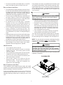 5
5
-
 6
6
-
 7
7
-
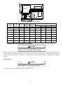 8
8
-
 9
9
-
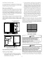 10
10
-
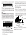 11
11
-
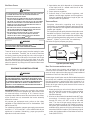 12
12
-
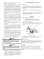 13
13
-
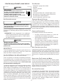 14
14
-
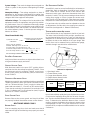 15
15
-
 16
16
-
 17
17
-
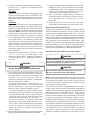 18
18
-
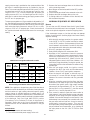 19
19
-
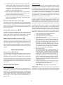 20
20
-
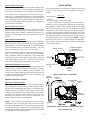 21
21
-
 22
22
-
 23
23
-
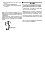 24
24
-
 25
25
-
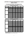 26
26
-
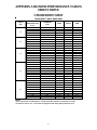 27
27
-
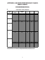 28
28
-
 29
29
-
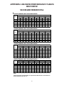 30
30
-
 31
31
-
 32
32
-
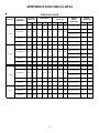 33
33
-
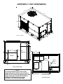 34
34
-
 35
35
-
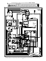 36
36
-
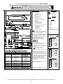 37
37
-
 38
38
-
 39
39
-
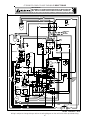 40
40
-
 41
41
-
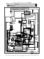 42
42
-
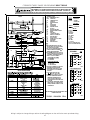 43
43
-
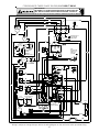 44
44
-
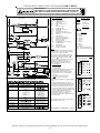 45
45
-
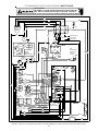 46
46
-
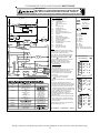 47
47
-
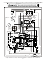 48
48
-
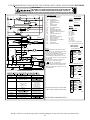 49
49
-
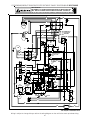 50
50
-
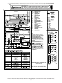 51
51
-
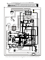 52
52
-
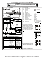 53
53
-
 54
54
-
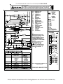 55
55
-
 56
56


GOODMAN Commercial Heating and Cooling Gas Unit CPG SERIES User manual
- Category
- Heat pumps
- Type
- User manual
Ask a question and I''ll find the answer in the document
Finding information in a document is now easier with AI
Related papers
-
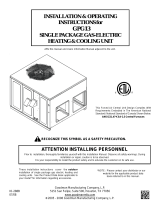 GOODMAN Gas Heater GPG13 User manual
-
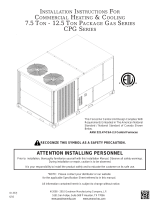 GOODMAN CPG SERIES User manual
-
GOODMAN CPH048 User manual
-
GOODMAN CPC072XXX3BXXX User manual
-
-
 GOODMAN A/GPG13 M SERIES User manual
-
GOODMAN Heating System PG 15 User manual
-
 GOODMAN 15 ton CPC Series User manual
-
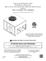 GOODMAN GPD1436090M41 Installation guide
-
 GOODMAN GPG1360115M41 Installation guide


Other documents
-
Daikin DSG0480903BXXX Installation guide
-
Reznor S6BQ Product information
-
Daikin DCG0601404BXXX Installation guide
-
Trane 4YCY4036B1075A Installation guide
-
Reznor RECB Installation guide
-
-
American Standard YCX048G1-H Installation guide
-
-
Broan Transformer Kit Installation guide
-
Reznor RDDA Installation guide