Reznor RECB Installation guide

Type
Installation guide
Form I-MAPSIII&IV, P/N 222917R9, Page 1
Form I-MAPSIII&IV (Version F.1)
Obsoletes Form I-MAPSIII (Version E)
Installation
Applies to: All MAPS
®
III&IV (Cabinets A, B, C, and D)
Model Series RCB, RDB, RCC, & RDC Packaged Makeup Air Cooling;
Models RDCB, RDDB, RDCC, & RDDC Packaged Makeup Air Cooling
with a Gas-Fired Heat Section; and Models RECB, REDB, RECC, &
REDC Packaged Makeup Air Cooling with an Electric Heat Section;
and Model JHUP Gas-Fired Curb Duct Furnaces
DANGER:
This unit contains R-410A high pressure refrigerant. Hazards exist that could result in
personal injury or death. Installation, maintenance, and service should only be performed by
an HVAC technician qualied in R-410A refrigerant and using proper tools and equipment.
Due to much higher pressure of R-410A refrigerant, DO NOT USE service equipment or
tools designed for R22 refrigerant.
R-410A
Refrigerant
A
G
E
N
C
Y
P
R
O
C
E
S
S
S
T
A
R
T
-
U
P
P
R
O
D
U
C
T
C
U
S
T
O
M
E
R
W
A
R
R
A
N
T
Y
C
O
N
V
E
R
G
E
N
T
Q
U
A
L
I
T
Y
S
Y
S
T
E
M
CQS
CQS
®
®
MAPS
®
III
Cabinet "D"
MAPS
®
III&IV Cabinets
"A", "B", and "C"
!
WARNING:
FIRE OR EXPLOSION HAZARD
Failure to follow safety warnings exactly could result in serious injury, death, or
property damage.
Be sure to read and understand the installation, operation, and service instructions in
this manual.
Improper installation, adjustment, alteration, service, or maintenance can cause
serious injury, death, or property damage.
Do not store or use gasoline or other ammable vapors and liquids in the vicinity
of this or any other appliance.
WHAT TO DO IF YOU SMELL GAS
Do not try to light any appliance.
Do not touch any electrical switch; do not use any phone in your building.
Leave the building immediately.
Immediately call your gas supplier from a phone remote from the building. Follow
the gas suppliers instructions.
If you cannot reach your gas supplier, call the re department.
Installation and service must be performed by a qualied installer, service agency,
or the gas supplier.
Form I-MAPSIII&IV, Page 2
1.1 Cautions and Warnings
There are warning labels on the unit, on the front page, and throughout this manual.
For your safety, comply with all warnings during installation, operation, and service of
this system. Denitions of the hazard intensity levels of the cautions, warnings, and
dangers are shown below.
1.0 General
HAZARD INTENSITY LEVELS
1. DANGER: Failure to comply will result in severe personal
injury or death and/or property damage.
2. WARNING: Failure to comply could result in severe personal
injury or death and/or property damage.
3. CAUTION: Failure to comply could result in minor personal
injury and/or property damage.
Denitions of Hazard
Intensity Levels used in
this Manual
1.0 General .....................................................2
1.1 Cautions and Warnings ................................. 2
1.2 General Information ...................................... 3
1.3 Warranty ....................................................... 3
1.4 Installation Codes ......................................... 4
2.0 Location and Moving ............................... 4
3.0 Receiving and Storage ............................4
3.1 Receiving ...................................................... 4
3.2 Storage ......................................................... 6
4.0 Clearances and Dimensions ................... 6
4.1 Clearances ................................................... 6
4.2 Dimensions .................................................. 7
5.0 Mounting ...................................................9
5.1 Approximate Weights .................................... 9
5.2 Curb Cap Base and Mounting .................... 10
5.3 Mounting a Horizontal Discharge System
on Cross Supports - D Cabinet only ............ 10
5.4 Mounting on a Roof Curb ........................... 10
5.5 Rigging and Lifting the MAPS
®
Units .......... 28
6.0 Mechanical .............................................30
6.1 Energy Recovery Module (Option ER1) .... 30
6.2 Optional Power Exhaust or Gravity
Exhaust Hood - Cabinets A, B, C ............... 31
6.3 Outside Air Hoods ...................................... 32
6.4 Duct Connections and Ductwork ............... 37
6.5 Condensate Drains .................................... 38
6.6 Blowers, Belts, and Drives .......................... 39
7.0 Electrical and Wiring .............................41
7.1 General ...................................................... 41
7.2 Supply Wiring ............................................. 41
7.3 Wiring Diagram, Unit Wiring Requirements,
and Optional Convenience Outlet ............... 43
7.4 Control Wiring ............................................. 43
7.5 Blower Motor ............................................... 43
7.6 Condenser Fan Motors and Fans ............... 44
7.7 Compressors .............................................. 44
8.0 Controls ..................................................45
8.1 Cooling/Dehumidication/Heating Control . 45
8.2 Supply Fan (blower) Start/Stop Control ...... 49
8.3 Control Options ........................................... 51
9.0 Optional Equipment ..............................53
9.1 Inlet Air Options .......................................... 53
9.2 Gas Heat - RDCB, RDDB, RDCC, RDDC .. 55
9.3 Electric Heat - RECB, REDB, RECC,
REDC .......................................................... 63
10.0 Commissioning and Startup ............... 64
10.1 General ..................................................... 64
10.2 Checklist Prior to Startup ......................... 64
10.3 Checklist - Startup ................................... 65
10.4 Checklist After Startup: ............................. 69
STARTUP Form for
Reznor
®
MAPS
®
Units ....... 70
APPENDIX ....................................................71
Cross-Reference by Model/Size and
Cabinet Size A, B, C or D ............................ 71
Pressure/Temperature Chart for Checking
Superheat and Subcooling .......................... 72
Wiring Diagram Option Identication ................ 73
References ...................................................74
Index .............................................................75
INSTALLATION RECORD ...........................76
Table of Contents
Form I-MAPSIII&IV, P/N 222917R9, Page 3
Models Description
RCB,
RCC
Makeup Air Cooling Packaged System, 1000-13000 CFM
RDCB,
RDCC
Makeup Air Cooling Packaged System, 1000-13000 CFM, with Gas
Heat Section (400-1600 MBH)
RECB,
RECC
Makeup Air Cooling Packaged System, 1000-13000 CFM, with
Electric Heat Section (10 - 180 kw)
RDB,
RDC
Makeup Air Cooling and Re-heat Pump Reheat Cycle Packaged
System, 1000-13000 CFM
RDDB,
RDDC
Makeup Air Cooling and Re-heat Pump Reheat Cycle Packaged
System, 1000-13000 CFM, with a Gas Heat Section (100-1600 MBH)
REDB,
REDC
Makeup Air Cooling and Re-heat Pump Reheat Cycle Packaged
System, 1000-13000 CFM, with Electric Heat Section (10 - 180 kw)
JHUP
Optional Curb Section with a 250 or 300 MBH Gas-Fired Duct
Furnace installed with a MAPS
®
unit with a Size 250 or 700 Heat
Section to provide 500 or 1000 MBH of heat
WARNING
Gas-red appliances are not designed for use in
hazardous atmospheres containing ammable vapors
or combustible dust, in atmospheres containing
chlorinated or halogenated hydrocarbons, or in
applications with airborne silicone substances.
WARNING
Should overheating occur, or the gas supply fail to shut
off, shut off the manual gas valve to the appliance before
shutting off the electrical supply.
WARNING
Do not use this appliance if any part has been under
water. Immediately call a qualied service technician to
inspect the appliance and replace any gas control that
has been under water.
Warnings for MAPS
®
Units with a Gas Heat
Section
1.2 General
Information
This booklet includes installation and operation information. Before beginning any pro-
cedure, carefully review the information, paying particular attention to the warnings.
If you do not have knowledge of local requirements, check with the local agencies who
might have requirements concerning this installation. Become familiar with the installa-
tion requirements of your particular model and make preparations for necessary sup-
plies, equipment, and manpower.
Handling of the R-410A refrigerant should only be performed by a certied HVAC tech-
nician in compliance with all codes and requirements of authorities having jurisdiction.
The instructions in this manual apply to the following MAPS
®
models:
1.3 Warranty
Refer to limited warranty information on the warranty form in the "Literature Bag"
shipped with this system. If an optional extended warranty applies, keep the extended
warranty information for future reference and verication of warranty.
Form I-MAPSIII&IV, Page 4
Massachusetts
Requirements
If being installed in the Commonwealth of Massachusetts, this unit must be installed by
a licensed plumber or licensed gas tter.
California Warning
Label
If a gas-red heat section is included and the system is being installed in the state of
California, the installer MUST attach the warning label on the outside of the heat sec-
tion access panel. The California Warning label is shipped in the "Literature Bag". If
installation is in California, select a dry, clean location on the heat section access panel
and adhere the label.
3.0 Receiving and
Storage
1.0 General
(cont'd)
1.4 Installation Codes
These packaged systems are certied by ETL to "Heating Cooling Equipment" (latest
edition), UL 1995 / CAN/CSA C22.2 No. 236-05. Electrical characteristics are shown
on the system rating plate. All cooling and re-heat pump reheat cycle circuits are fac-
tory-charged with R-410A refrigerant.
Models RDCB, RDDB, RDCC, and RDDC include a single or double gas heat sec-
tion. The gas-red, power-vented duct furnace uses the Reznor
®
TCORE
2
®
combustion
system. The heat section is available in nine sizes from 400 to 1600 MBH for use with
natural gas. The furnace is certied by ETL to the latest editions of both ANSI Z83.8
and CSA 2.6 for use in the United States and Canada. The ETL label, type of gas, and
the ring rate are shown on the heat section rating plate.
Approval and
Installation Codes
2.0 Location and
Moving
This outdoor unit is designed to be set on a slab, on a roof curb, or on rails (D Cabinet)
and must be level for proper operation. When selecting the location, check the follow-
ing:
Installation location must comply with local codes.
Location on a roof depends on building structure. Refer to the weights in
Paragraph 5.1.
Comply with required clearances in Paragraph 4.1.
Position the unit so that the outside air inlet will not be facing into the prevailing
wind.
Before moving unit, refer to Paragraph 5.6 for rigging information. See NOTE on
left.
3.1 Receiving
This system was test operated and inspected at the factory and was in operating con-
dition. If the equipment has incurred any damage in shipment, document the damage
with the carrier and immediately contact your Reznor
®
distributor.
Check the entire unit for damage paying particular attention to the structural integrity of
the lifting points and the condenser fan section. Check the condenser fan guards and
the fan blades.
On the inside of the door of the control compartment, locate the system rating plate
(See FIGURE 1A.). Check the specications and the electrical characteristics and ver-
ify compatibility with the electric supply at the installation site.
If installing a MAPS
®
unit with a heat section, check the rating plate (See FIGURE
1B.) on the inside cover of the heat section. Be sure that the rating plate information is
compatible with the electric and/or gas supply at the installation site.
Check for shipped-separate accessories and shipped-loose parts. All systems will
have a shipped-loose discharge air sensor. The roof curb is shipped separately (See
Paragraph 5.2), and in most cases, in advance of the unit. The outside air hood is
shipped in a separate carton for eld assembly and installation. (NOTE: Install the
hood after the unit is in place.) An optional energy recovery module is shipped as a
separate component to be mated to the unit at the installation site.
If ordered, other items that would be shipped separately include a disconnect switch,
various types of space-mounted sensors and controls, a duct smoke detector, a VFD,
a restat, extra belts, and extra lters.
Shipped-Separate
Accessories and
Shipped-Loose Parts
IMPORTANT NOTE: A
Cabinet Size C or D unit
MUST be loaded and
unloaded using ALL lifting
points and spreader bars.
DO NOT attempt to move
a MAPS
®
Cabinet Size C
or D with a fork lift.
Form I-MAPSIII&IV, P/N 222917R9, Page 5
FIGURE 1A - Sample of System
Rating Plate (applies to all models)
System Rating Plate Key:
A = Model
B = Manufacturing Date (Month/Year)
C = Blower Motor HP
D = Volts/Phase/Hertz
E = Full Load Amps of Blower Motor
F = Minimum Circuit Ampacity
G = Maximum Fuse Size
H = Quantity - Compressor A
I = Rated Load Amps of Compressor A
J = Locked Rotor Amps of Compressor A
K = Quantity - Compressor B
L = Rated Load Amps of Compressor B
M = Locked Rotor Amps of Compressor B
N = Quantity - Compressor C
O = Rated Load Amps of Compressor C
P = Locked Rotor Amps of Compressor C
Q = Quantity - Compressor D
R = Rated Load Amps of Compressor D
S = Locked Rotor Amps of Compressor D
GG = Quantity - Compressor E
HH = Rated Load Amps of Compressor E
II = Locked Rotor Amps of Compressor E
T = Quantity Condenser Fan Motors
U = Rated Load Amps of Condenser(s)
V = Refrigerant Charge (lbs) - Circuit A
W = Refrigerant Charge (lbs) - Circuit B
X = Refrigerant Charge (lbs) - Circuit C
Y = Refrigerant Charge (lbs) - Circuit D
JJ = Refrigerant Charge (lbs) - Circuit E
Z = Condenser Fan Motor HP
AA = Test Pressure High (psig)
BB = Test Pressure Low (psig)
CC = SCFM Airow
DD = External Static
Pressure (" w.c.)
EE = Drive (Option AM)
FF = Wiring Diagram No.
Gas Heat Section Rating Plate Key:
AA/A = ANSI Standard Date
AA1/A1 = CSA Standard Date
C = Model No.
D = Voltages
E = Type of Gas (natural)
F = Orice Size
H = Normal BTUH Input (sea level)
I = Thermal Output BTUH (sea level)
J = Minimum BTUH Input (sea level)
K = Manifold Pressure
L = Minimum Gas Supply Pressure
M = Maximum Throughput
N = Minimum Throughput
P = Manufacturing Date (Month/Year)
Q = Altitude in Feet
R = Altitude in Meters
FIGURE 1B - Sample of a Gas
Heat Section Rating Plate
REZNOR
®
MERCER, PA., U.S.A. 16137
MADE IN USA
FOR INDUSTRIAL/COMMERCIAL USE ONLY
SUITABLE FOR OUTDOOR USE
MODEL [ A ] [ B ]
SERIAL NO. [ ]
ELECTRICAL
[D] VOLTS +/- 10% [D] PHASE [D] HZ
MINIMUM CIRCUIT AMPACITY (MCA) [ F ] AMPS
MAXIMUM FUSE SIZE/*CKT BREAKER [ G ] AMPS
QTY FLA(EA) HP(EA)
SUPPLY AIR BLOWER MOTOR 1 [ E ] [ C ]
CONDENSER FAN MOTOR (S) [ T ] [ U ] [ Z ]
QTY RLA (EA) LRA (EA)
COMPRESSOR A [ H ] [ I ] [ J ]
COMPRESSOR B [ K ] [ L ] [ M ]
COMPRESSOR C [ N ] [ O ] [ P ]
COMPRESSOR D [ Q ] [ R ] [ S ]
COMPRESSOR E [ GG ] [ HH ] [ II ]
CIRCUITS A B C D E
REFRIGERANT - R-410a CHARGE - LBS
[ V ] [ W ] [ X ] [ Y ] [ JJ ]
TEST PRESSURES HIGH 600 PSIG LOW 45 PSIG
EQUIPPED FOR OPERATION AT AN AIR FLOW OF [ CC ] SCFM
AGAINST A STATIC PRESSURE OF [ DD ] INCHES WATER COLUMN
DRIVE RPM [ EE ]
WIRE DIAGRAM [ FF ]
REFER TO RATING PLATE IN THE FURNACE SECTION (WHEN USED)
FOR ADDITIONAL INFORMATION.
*HACR TYPE REQUIRED PER NEC
REZNOR
®
MERCER, PA USA 16137
DUCT FURNACE/GÉNÉRATEUR D'AIR CHAUD À GAINE
CATEGORY III/CATÉGORIE III
FOR INDUSTRIAL/COMMERCIAL USE ONLY
POUR USAGE INDUSTRIEL/COMMERCIAL
ANSI Z83.8 [AA] - [ A ]
CSA 2.6 [AA1] - [A1] DUCT FURNACE/GÉNÉRATEUR D'AIR CHAUD À GAINE
MODEL/MODÈLE [ C ] [ P ]
SERIAL NO. / #DE SÉRIE: [ ]
VOLTAGE [ D ]
TYPE OF GAS/TYPE DE GAZ: [ E ]
ALTITUDE [ Q ] FEET/PIEDS, [ R ] MÈTRES
BURNER ORIFICE SIZE [ F ] DRILL HAS BEEN FACTORY ADJUSTED
BRULEUR DIMENSION DE L'ORIFICE [ F ] FORET
NORMAL INPUT/ENTRÉE NORMALE (TOTAL)
[ H ] BTU/HR
THERMAL OUTPUT / RENDEMENT THERMIQUE (TOTAL)
[ I ] BTU/HR
MINIMUM INPUT/ENTRÉE MIN.
[ J ] BTU/HR
NORMAL MANIFOLD PRESSURE
[ K ] IN.W.C.
PRESSION NORMALE DE LA TUB
[ K ] PO/COL D'EAU
MIN. PERMISSIBLE GAS SUPPLY PRESSURE
FOR PURPOSE OF INPUT ADJUSTMENT.
[ L ] IN.W.C.
PRES. D'ALIM. MIN. ACCEPTABLE DE GAZ POUR
DES FIN DE RÉGLAGE DE L'ENTRÉE
[ L ] PO/COL D'EAU
MAXIMUM THROUGHPUT / MINIMUM THROUGHPUT [ M ] / [ N ] C.F.M.
CONSOMMATION MAXIMUM / MINIMUM [ M ] / [ N ] PI3/MN
System Rating
Plate(s)
Rating Plate for
Gas-Fired Furnace on
Models RDCC & RDDC
MAPS® Cabinets A, B, and C -
System Rating Plate(s) are on
the inside of the High Voltage
Electrical Compartment Door
Filter
Access
Coil
Access
Fan & Motor
Access
Control
Access
Heat
Access
Heat
Access
Left Side View (Control Side)
MAPS® Cabinet D
Wiring Diagram
Rating Plate
(inside of control access door)
Rating Plate
Location - Cabinets
A, B, and C
Rating
Plate
Location -
Cabinet D
Form I-MAPSIII&IV, Page 6
4.0 Clearances
and
Dimensions
3.2 Storage
If this system is going to be stored, take precautions to prevent condensate formation
inside the electrical compartments and motors. To prevent damage to the unit, do not
store sitting on the ground.
Battery backup for controls will maintain for approximately one year. If backup expires,
controls will need to be reprogrammed.
3.0 Receiving
and Storage
(cont'd)
Provide minimum clearances as shown in FIGURE 2A or 2B. Minimum clearances
are required to ensure proper operation and access for service. If a heat section is
included, clearance to combustibles is required. Clearance to combustibles is dened
as the minimum distance from the heater to a surface or object that is necessary to
ensure that a surface temperature of 90°F (50°C) above the surrounding ambient tem-
perature is not exceeded.
4.1 Clearances
FIGURE 2A - MAPS
®
A, B, & C Cabinet Clearances
For cross-reference of cabinet size to model
size, see APPENDIX, pages 71-72.
Top Clearance: All Models - 60"
(1524mm)
Bottom Clearance: All Models - 0"
(0mm)
Additional Gas Heat Section
Clearance Information
If installing a unit with a gas heat
section, the 40" (1016mm) service
clearance provides for clearance to
combustibles and required space for
combustion air inlet and venting. Vent
terminal must be 4 feet (1.22M) from
gas and electric meters, regulators,
and relief equipment.
FIGURE 2B - MAPS
®
III D Cabinet Clearances
For cross-reference of cabinet size to model
size, see APPENDIX, pages 71-72.
Top Clearance: All Models - 60"
(1524mm)
Bottom Clearance: All Models - 0"
(0mm)
Additional Gas Heat Section
Clearance Information -
If installing a unit with a gas heat
section, the 4 ft 7 inch (1.4M)
service clearance provides for
clearance to combustibles and
required space for combustion air
inlet and venting. Vent terminal
must be 4 feet (1.22M) from gas
and electric meters, regulators,
and relief equipment.
Bottom Supply
Air Opening
Bottom Return
Air Opening
Outside Air Hood
Top View
Airflow
All Models with
gas or electric heat
- Clearance to
Combustibles -
4 ft (1.22M)
Models RDCB, RDCC,
RDDB & RDDC -
Service Clearance is
4 ft 7 inches (1.4M)
Models RECB, RECC,
REDB & REDC
- Service Clearance
is 4 ft (1.22M)
Door Width (largest door)
Cabinet A, 23” (584mm)
Cabinet B, 27“ (686mm)
Cabinet C, 32” (813mm)
Door Width (largest door)
Cabinets A&B, 26” (660mm)
Cabinet C, 32-1/2” (826mm)
All Models - Minimum Service
Clearance - Width of the Unit
All Models - 24” (610mm)
Outside
Air Hood,
Option
AS16
All Models - 24” (610mm)
Models RDCB, RDDB, RECB, REDB - Clearance to
Combustibles - 40” (1016mm)
Models RDCB & RDDB - Service Clearance - 40” (1016mm)
Models RECB & REDB - Service Clearance - 64” (1626mm)
All Models - 87” (2210mm) is minimum clearance
to remove coil section sliding drain pan
Top View
Control
Side
Airflow
All Models - 24” (610mm)
IMPORTANT: The area above the condenser fans MUST ALWAYS be totally open
space to allow proper airow through the condenser coils.
Form I-MAPSIII&IV, P/N 222917R9, Page 7
FIGURE 3A - General Arrangement and Dimensions (inches/mm) - Cabinets A, B, and C
4.2 Dimensions
Cabinet A B C D E F G H J K L M* N* P*
Dimensions - inches
A
84 73-7/8 49 43-7/8 76-1/4
26-3/4 (Opt AS16);
44 (Opt AS19)*
41-7/8 39-1/2 72-5/8 24-1/4 20-1/4 12-1/2 27 17-1/2
B
84 73-7/8 49 43-7/8 76-1/4
56-7/8 54-1/2 87-5/16 36-1/4 20-1/4 12-1/2 39 17-1/2
C
113 102-1/2 67-3/4 62-5/8 105-3/16 37-5/8 (Opt AS16&AS19)
68-1/2 66 101-3/16 49-7/8 25-7/8 15-1/2 48 24-3/4
Dimensions - mm
A
2134 1870 1245 1114 1937
679 (Opt AS16);
1118 (Opt AS19)*
1064 1003 1837 616 514 318 686 445
B
2134 1870 1245 1114 1937
1445 1384 2218 921 514 318 991 445
C
2870 2604 1721 1591 2672 986 (Opt AS16&AS19)
1740 1677 2570 1267 657 394 1219 629
*Outside air hood Option AS19 is required with power exhaust or energy recovery module option.
Cabinet & Heat Size Q*
Dimensions - inches
A
No Heat 26-1/2
Electric Heat 26-1/2
100 MBH (gas) 19
150 MBH (gas) 26-1/2
200 MBH (gas) 34
B
No Heat 49
Electric Heat 49
250 MBH (gas) 41-1/2
300 MBH (gas) 49
C
No Heat
32-5/8**
49-5/8***
Electric Heat 49-5/8
400 MBH (gas) 32-5/8
500 MBH (gas) 44-5/8
600 MBH (gas) 49-5/8
700 MBH (gas) 54-5/8
Dimensions - mm
A
No Heat 673
Electric Heat 673
100 MBH (gas) 483
150 MBH (gas) 673
200 MBH (gas) 864
B
No Heat 1245
Electric Heat 1245
250 MBH (gas) 1054
300 MBH (gas) 1245
C
No Heat
829**
1260***
Electric Heat 1260
400 MBH (gas) 829
500 MBH (gas) 1133
600 MBH (gas) 1260
700 MBH (gas) 1387
4.2.1 Dimensions - Cabinet Sizes A, B, and C
Bottom
Supply
Air
Opening
Bottom Return
Air Opening
Airflow
Outside
Air Hood
Outside
Air Hood
Power Inlet
2” (51mm) ø
8-3/16 (208)
Control
Panel
Coil
Access
Front
View
8-3/4 (222)
3-3/16 (81)
Motor and
Blower
Access
Filter and Reheat
Compressor Access
Drain
1” NPT
Control Voltage
Inlet
11
(279)
77-1/2 (1969)
Tubing
Access
Compressor
Access
High
Voltage
Electrical
Gas Heat
Section
Inlet Air End View
(with hood installed;
optional exhaust not shown)
Condenser
Section
Q
P
Optional Power Exhaust
(See dimensions,
Paragraph 6.2.)
E
F
8-1/16
(205)
C
D
A
(length of base)
B (inside of curb cap)
Tubing
Access
Compressor
Access
High
Voltage
Electrical
Electric Heat
Section
Disconnect Switch
Inlet Air End View
(without hood)
Condenser
Section
G (width of base)
H (inside curb cap)
Top
View
Control Side
View
End Views -
Models with
Gas Heat
Section
End Views -
Models with
Electric Heat
Section
Combustion Air Intake Panel
Vent
(NOTE: Two sets of End
Views shown for appearance.
Dimensions shown in End
Views apply to all Models.)
End of Base to
Gas Connection
Sizes A&B 8-1/4 (210)
Size C 9-3/8 (238)
K
M
N
L
Gas
J
NOTES:
*M, N, P, & Q are opening sizes
in the bottom of the cabinet. Duct
anges are in the roof curb; see
Form I-OPT-C for duct connection
dimensions.
**Applies to Model RCB 190, 216;
RCC 190; RDB 248, 262, 272,
288; RDC 248, 262
*** Applies to Models RCB & RCC
298, 410; RDB & RDC 354, 370,
468, 482
For cross-reference of cabinet
size to model size, see
APPENDIX, pages 71-72.
Form I-MAPSIII&IV, Page 8
Model RDCB & RDDB NOTES:
Heat Sizes 500, 600, 700, 800 have one heat module.
Heat Sizes 1000, 1200, 1400, 1600 have two heat modules
(illustrated).
Model and Cooling
Size
with Gas Heat
Section Size
CODES (FIGURE 3B)
A B C
Dimensions - inches (±1/16)
RCB, RECB 360, 480,
600, 720
N/A 208-3/8 -- 201-15/16
RDCB 360, 480, 600,
720
500, 600, 700, 800 208-3/8 80-3/16 201-15/16
1000, 1200, 1400, 1600 240-3/4 80-13/16 234-5/16
RDB, REDB 418, 444,
602, 722, 842
N/A 208-3/8 -- 201-15/16
RDDB 418, 444, 602,
722, 842
500, 600, 700, 800 208-3/8 80-3/16 201-15/16
1000, 1200, 1400, 1600 240-3/4 80-13/16 234-5/16
Dimensions - mm (±2)
RCB, RECB 360, 480,
600, 720
N/A 5293 -- 5129
RDCB 360, 480, 600,
720
500, 600, 700, 800 5293 2037 5129
1000, 1200, 1400, 1600 6115 2053 5952
RDB, REDB 418, 444,
602, 722, 842
N/A 5293 -- 5129
RDDB 418, 444, 602,
722, 842
500, 600, 700, 800 5293 2037 5129
1000, 1200, 1400, 1600 6115 2053 5952
FIGURE 3B - General
Arrangement
and Dimensions -
inches (mm) of
D Cabinet Models
NOTES:
Gas heat section
information applies only
to Models RDCB and
RDDB.
Discharge is either
horizontal or vertical (not
both).
Return air opening
(vertical only) is optional.
4.2 Dimensions (cont'd)
4.2.2 Dimensions of Cabinet D Size Models and Cabinet D Door Hinges
Cabinet D Door Hinges / Handles
The lter, coil, and fan/motor cabinet doors can be
opened from the left or right. On the side of the door
to be opened, unlock the two hinges with an allen key.
Pull out unlocked "fronts" of the hinges to 90 degrees to
expose handles needed to open the door.
Re-lock hinges when doors are closed.
Door Hinges - Use an allen key to unlock
hinges to open D Cabinet doors from left or
right.
Locked
Unlocked
3/4 (19)
3/4 (19)
3/4 (19)
3/4
(19)
71-7/8
(1826)
18-3/16 (462)
Outside
Air
Inlet
36
(914)
34-1/4
(870)
20-5/8
(524)
14-1/2
(368)
3-1/16
(78)
Filter
Access
Coil
Access
Fan & Motor
Access
71-5/8 (1819)
Coil
Drain
100-5/8 (2556)
Gas
Electric
(24V left; supply right)
3-3/8 (86)
A
C - Inside of Base
B
3-1/16
(78)
4-7/8 (124)
Bottom
of Base
to Curb
Mounting
Surface
16-1/2
(419)
82-5/16
(2091)
85-9/16
(2173)
Control
Access
Heat
Access
Heat
Access
Combustion
Air Hood
3/4 (19)
3/4 (19)
3/4
(19)
3/4 (19)
47-11/16
(1211)
100-1/4 (2546)
26-3/4
(679)
21-5/8
(549)
11-1/4
(286)
Top View
Front View
Left Side View (Control Side)
Return Air Duct
Connection
3/4
(19)
3/4
(19)
3/4
(19)
3/4
(19)
72
(1829)
10 (254)
10-3/16
(259)
19-7/8 (505)
93-3/4
(2381)
Inside
of
Base
3/4 (19)
3/4
(19)
3/4
(19)
3/4
(19)
26-3/4
(679)
47-11/16 (1211)
11-1/4 (286)
Vertical
Discharge Duct
Connection
Roof Curb Mounting Surface
Bottom View
18-1/4 (464)
Horizontal
Discharge
Duct Connection
Condenser Section
Compressors
48-11/32” (1228mm)
54-1/4”
(1378mm)
6-1/4” (159mm)
Side View
Hood
(Option AS16)
FIGURE 4 - D Cabinet Door Hinges
Form I-MAPSIII&IV, P/N 222917R9, Page 9
5.0 Mounting
5.1 Approximate Weights
The weights listed here are approximate and are not corner weights. If corner weights
are needed, refer to www.RezSpec.com or call 1-800-695-1901.
5.1.1 Accessory
Weights
Add the accessory weight to
the base weight below.
5.1.2 Approximate Weights - Models RCB, RDB, RCC, & RDC Base
5.1.3 Approximate Weights - Models RDCB, RDDB, RDCC, & RDDC Base
Models RCB and RCC (cooling only) and Models RDB and RDC (cooling with reheat) Weight (lbs)
Model RCB
or RCC
Cooling
Only
Size 060 078 090 118 120 136 160 186 200 190 216 298 410 360 480 600 720
Cabinet A A A A A A B B B C C C C D D D D
Lbs 775 904 915 916 916 1019 1280 1348 1416 1416 1891 1891 2276 6100 6296 6436 6458
Model RDB
or RDC
Cooling w/
Reheat
Size 084 102 114 142 144 162 184 196 210 222 224 236 257 248 262 272 288 354 370 468 482 418 444 484 538 564 602 658 684 722 804 842
Cabinet A A A A A A B B B B B B B C C C C C C C C D D D D D D D D D D D
Lbs 982 982 993 972 972 1097 1372 1440 1440 1440 1508 1508 1508 2018 2018 2018 2018 2403 2403 2727 2756 6235 6235 6235 6431 6431 6431 6582 6582 6582 6593 6593
Model RCB and RCC (cooling only) and Models RDB and RDC (cooling with reheat) Weight (kg)
Model RCB
or RCC
Cooling
Only
Size 060 078 090 118 120 136 160 186 200 190 216 298 410 360 480 600 720
Cabinet A A A A A A B B B C C C C D D D D
kg 352 410 415 415 415 462 581 611 642 642 858 858 1032 2767 2856 2919 2929
Model RDB
or RDC
Cooling w/
Reheat
Size 084 102 114 142 144 162 184 196 210 222 224 236 257 248 262 272 288 354 370 468 482 418 444 484 538 564 602 658 684 722 804 842
Cabinet A A A A A A B B B B B B B C C C C C C C C D D D D D D D D D D D
kg 445 445 450 498 498 498 622 653 653 653 684 684 684 915 915 915 915 1090 1090 1237 1250 2828 2828 2828 2917 2917 2917 2986 2986 2986 2991 2991
Cabinet Size A B C D
Optional Accessory lbs (kg) lbs (kg) lbs (kg) lbs (kg)
Outside Air Hood (Option AS16 or AS19) 35 16 45 (20) 80 (36) 147 (67)
Model JHUP-25 Curb Duct Furnace (Option JH25)
530 (240)
Model JHUP-30 Curb Duct Furnace (Option JH30)
830 (376)
Energy Recovery Module (Option ER1A, ER1B, ER1C))
767 (348) 1006 (456) 1334 (605)
Downow Roof Curb (Option CJ3)
770 (349)
Downow Roof Curb (Option CJ31)
93 (42) 105 (48)
235 (107)
Downow Roof Curb for unit with Energy Recovery Module (Option CJ34) 254 (115) 292 (292) 365 (166)
32" (813mm) High Horizontal Flow Roof Curb (Option CJ50) 353 (160) 434 (197)
32" (813mm) High Horizontal Flow Roof Curb for unit with ER (Option CJ54)
675 (306) 785 (356)
36" (914mm) High Horizontal Flow Roof Curb (Option CJ49)
654 (297)
36" (914mm) High Horizontal Flow Roof Curb for unit with ER (Option CJ53)
1087 (493)
5.1.4 Approximate Weights - Models RECB, REDB, RECC, & REDC Base
NOTE: Weights listed are for the largest kw size available in the model size.
Weight (lbs) - Cabinet C, Models RDCB, RDDB, RDCC,
& RDDC and Cabinet D, Models RDCB & RDDB
Weight (kg) - Cabinet C, Models RDCB, RDDB, RDCC, &
RDDC and Cabinet D, Models RDCB & RDDB
RDCB
or
RDCC
Cabinet
Gas Heat Section Size
RDCB
or
RDCC
Cabinet
Gas Heat Section Size
-400 -500 -600 -700 -800 -1000 -1200 -1400 -1600 -400 -500 -600 -700 -800 -1000 -1200 -1400 -1600
190 C
2190 2253
2397
2400
**
190 C
993 1022
1087
1089
**
216 C
2190 2253
2397
2400
**
216 C
993 1022
1087
1089
**
298 C
2575 2638
2782
2785
**
298 C
1168 1197
1262
1263
**
410 C
2900 2963
3107 3110
**
410 C
1315 1344 1409 1411
**
360 D
6362
6412
6462
6512 6630 6728 6826 6924
360 D
2886
2908
2931
2954 3007 3076 3096 3141
480 D
6558
6608 6658
6708
6826 6924 7022 7120
480 D
2975 2997 3020
3043
3096 3141 3185 3230
600 D
6709
6759 6809
6859
6977 7075 7173 7271
600 D
3043 3066 3086
3111
3165 3209 3254 3298
720 D
6720
6770 6820
6870
6988 7086 7184 7282
720 D
3048 3071 3094
3116
3170 3214 3259 3303
RDDB
or
RDDC
Cabinet
Gas Heat Section Size
RDDB
or
RDDC
Cabinet
Gas Heat Section Size
-400 -500 -600 -700 -800 -1000 -1200 -1400 -1600 -400 -500 -600 -700 -800 -1000 -1200 -1400 -1600
248 C
2317 2380 2524 2527
**
248 C
1051 1080 1145
1146
**
262 C
2317 2380 2524 2527
**
262 C
1051 1080 1145
1146
**
272 C
2317 2380 2524 2527
**
272 C
1051 1080 1145
1146
**
288 C
2317 2380 2524 2527
**
288 C
1051 1080 1145
1146
**
354 C
2702 2765
2909
2912
**
354 C
1226 1254
1320
1321
**
370 C
2702 2765
2909
2912
**
370 C
1226 1254
1320
1321
**
468 C
3026 3089 3233 3236
**
468 C
1373 1401 1466
1468
**
482 C
3055 3118
3233
3235
**
482 C
1386
1414
1466
1468
**
418 D
6497 6547 6597
6647
6765 6863 6961 7059
418 D
2947 2970
2992
3015
3069
3113 3157 3202
444 D
6497 6547 6597
6647
6765 6863 6961 7059
444 D
2947 2970
2992
3015
3069
3113 3157 3202
484 D
6497 6547 6597
6647
6765 6863 6961 7059
484 D
2947 2970
2992
3015
3069
3113 3157 3202
538 D
6693 6743 6793
6843 6961 7059 7157 7255
538 D
3035 3059
3081
3104 3157 3202 3246 3291
564 D
6693 6743 6793
6843 6961 7059 7157 7255
564 D
3035 3059
3081
3104 3157 3202 3246 3291
602 D
6693 6743 6793
6843 6961 7059 7157 7255
602 D
3035
3059 3081 3104 3157 3202 3246 3291
658 D
6844 6894 6944
6994 7112 7210 7308 7406
658 D
3104
3127 3150 3172 3226 3270 3315 3359
684 D
6844 6894 6944
6994 7112 7210 7308 7406
684 D
3104
3127 3150 3172 3226 3270 3315 3359
722 D
6844 6894 6944
6994 7112 7210 7308 7406
722 D
3104
3127 3150 3172 3226 3270 3315 3359
804 D
6855 6905 6955
7005 7123 7221 7319 7417
804 D
3109
3132 3155 3177 3231 3275 3320 3364
842 D
6855 6905 6955
7005 7123 7221 7319 7417
842 D
3109
3132 3155 3177 3231 3275 3320 3364
Weight (lbs) - Cabinets A & B, Models
RDCB, RDDB, RDCC, & RDDC
Weight (kg) - Cabinets A & B, Models
RDCB, RDDB, RDCC, & RDDC
Size
DX Cooling and Gas Heat Section
Size
DX Cooling and Gas Heat Section
Cabinet A Cabinet B Cabinet A Cabinet B
-100 -150 -200 -250 -300 -500 -100 -150 -200 -250 -300 -500
060 885 1000 1025
060 401 454
465
078 1014 1129 1154 1157 1157
*
078 460 512
523
525 525
*
090 1026 1140 1165 1168 1168
*
090 465 517 528 530 530
*
118 1004 1119 1144 1147 1147
*
108 455 508 519 520 520
*
136 1129 1244
1269
1272 1272
*
139 512 564
575
577 577
*
160
1533 1533
*
164
695 695
*
186
1601 1601
*
166
726 726
*
200
1669 1669
*
198
575 575
*
Size
DX Cooling with Reheat & Gas Heat Section
Size
DX Cooling w/ Reheat & Gas Heat Section
Cabinet A Cabinet B Cabinet A Cabinet B
-100 -150 -200 -250 -300 -500 -100 -150 -200 -250 -300 -500
084 1092 1207 1232
084 495 547 559
102 1092 1207 1232 1235 1235
*
102 495 547 559 560 560
*
114 1103 1218 1243 1246 1246
*
114 500 552 564 565 565
*
142 1082 1197 1222 1225 1225
*
142 491 543 555 556 556
*
162
1322 1347 1350 1350
*
126
600 611 612 612
*
184
1625 1625
*
188
737 737
*
210
1693 1693
*
220
768 768
*
222
1693 1693
*
230
768 768
*
224
1761 1761
*
234
799 799
*
236
1761 1761
*
280
799 799
*
*Weight of a B Cabinet Size 500 is a Size 250 plus JH250
from the Accessory Table above.
**Weight of a C Cabinet Size 1000 is a Size 700 plus
JH300 from the Accessory Table above.
Weight (lbs) - Models RECB & RECC (cooling and electric heat) and Models REDB & REDC (cooling, electric heat, and dehumidication)
Model
RECB or
RECC
Cooling
Only
Size 060 078 090 118 120 136 160 186 200 190 216 298 410 360 480 600 720
Cabinet A A&B A&B A&B A&B A&B B B B C C C C D D D D
Lbs 815 944 995 974 974 1099 1360 1428 1496 1971 1971 2356 2681 6100 6296 6436 6458
Model
REDB or
REDC
Cooling
w/Reheat
Size 084 102 114 142 144 162 184 196 210 222 224 236 257 248 262 272 288 354 370 468 482 418 444 484 538 564 602 658 684 722 804 842
Cabinet A A&B A&B A&B A&B A&B B B B B B B B C C C C C C C C D D D D D D D D D D D
Lbs 1022 1022 1073 1052 1052 1177 1452 1440 1520 1520 1588 1588 1588 2098 2098 2098 2098 2483 2483 2807 2836 6235 6235 6235 6431 6431 6431 6582 6582 6582 6593 6593
Weight (kg) - Models RECB & RECC (cooling and electric heat) and Models REDB & REDC (cooling, electric heat, and dehumidication)
Model
RECB or
RECC
Cooling
Only
Size 060 078 090 118 120 136 160 186 200 190 216 298 410 360 480 600 720
Cabinet A A&B A&B A&B A&B A&B B B B C C C C D D D D
kg 361 428 451 442 442 499 617 648 679 858 858 1032 1180 2767 2856 2919 2929
Model
REDB or
REDC
Cooling
w/Reheat
Size 084 102 114 142 144 162 184 196 210 222 224 236 257 248 262 272 288 354 370 468 482 418 444 484 538 564 602 658 684 722 804 842
Cabinet A A&B A&B A&B A&B A&B B B B B B B B C C C C C C C C D D D D D D D D D D D
kg 463 463 487 477 477 534 659 653 689 689 720 720 720 952 952 952 952 1126 1126 1273 1286 2828 2828 2828 2917 2917 2917 2986 2986 2986 2991 2991
Form I-MAPSIII&IV, Page 10
5.4 Mounting on a
Roof Curb
MAPS
®
packaged heating/cooling systems have a curb cap base designed for use
with a full perimeter curb. When on a roof, either a manufacturer-designed roof curb, a
eld-supplied roof curb, or other eld-supplied support is required. NOTE: A Reznor
®
roof curb is required with a vertical discharge and/or bottom return air to provide a
weatherproof installation.
A MAPS
®
III Cabinet D size system which has an optional horizontal discharge may be
set directly on a concrete slab or cross supports (See Paragraph 5.3 below).
5.2 Curb Cap Base
and Mounting
MUST be sealed
between curb cap
rail and roof curb.
Optional or
Field-Supplied
Roof Curb fits
under and inside
the curb cap.
Base of curb cap edge may be
set directly on a cement slab or
on perpendicular supports.
4-7/8”
(124mm)
Edge of curb cap extends
down over roof curb.
Cabinet Wall
Curb
Cap Rail
5.3 Mounting a
Horizontal
Discharge
System on
Cross Supports
(no roof curb) -
D Cabinet only
Prior to installation, be sure that the method of support is in agreement with all local
building codes and is suited to the climate. If considering an installation without a roof
curb in snow areas, the support under the system should be at least 12” (305mm)
higher than the roof surface. IMPORTANT NOTE: If setting cross supports on the roof
surface and not decking, be sure to have sufcient tread material under the supports to
adequately spread the load and prevent “sinking” into the roong material.
The eld supplied, weather resistant, cross-support structure must be secure and
adequate for the weight of the system (Refer to weights in Paragraph 5.1). See width
dimensions in Paragraph 4.2.
Damper
Access
Coil
Access
Fan & Motor
Access
Control
Access
Heat
Access
Heat
Access
FRONT VIEW
SIDE
VIEW
There MUST be no less than five cross supports. A cross support MUST be in the approximate
locations shown in the Side View. ALL cross supports MUST extend the full width of the unit as shown
in the Front View. Cross supports must be weather resistant and must be able to support the unit weight.
Supports should be a minimum height of 12” (305mm) in snow areas.
Horizontal
Discharge
Cross Supports
2
3
5
1
4
FIGURE 6 - Cross Support Requirements (no roof curb) - Cabinet D
Curbs available with the system are fully enclosed and insulated. Other characteristics
by cabinet size and option are listed below.
FIGURE 5 - Cross
Section View of Curb
Cap Base
5.0 Mounting
(cont'd)
*For cross-reference of
cabinet size to Model Size,
see Appendix, pages 71-72.
MAPS
®
Cabinet Size*
Roof Curb
Discharge Option Height
A, B, & C
Down with Duct
Connections in the
Curb
CJ31
14" (356mm)
A, B, & C w/Energy Recovery Module CJ34
D CJ3 16" (406mm)
A & B
Horizontal Duct
Connections in the
Curb (at the inlet air
side of the unit)
CJ50 32" (813mm)
C CJ49 36" (914mm)
A & B w/Energy Recovery Module CJ54 32" (813mm)
C with Energy Recovery Module CJ53 36" (914mm)
D - horizontal discharge connection on unit (no return air) CJ3 16" (406mm)
Form I-MAPSIII&IV, P/N 222917R9, Page 11
If the application is sound sensitive, consider installing a eld-supplied vibration isola-
tion curb or specialty sound attenuation curb.
Whether using an optional roof curb available with the system or a eld-supplied curb,
the curb must be secure, square, and level. When the unit is being placed on a roof,
location depends on the roof structure and is the responsibility of the installer. For
condensate drainage and proper operation, it is important that the installation be level.
Position the curb so that the outside air inlet of the unit will not be facing into the pre-
vailing wind.
Always comply with the unit clearances in Paragraph 4.1.
Duct Connections - Optional down discharge roof curbs are designed for ductwork to
be inserted in the duct connection opening(s) from above the curb prior to setting the
unit on the curb.
5.4.1 Downow Roof
Curbs for MAPS
®
Cabinets A, B, and C
Layout and Components
Both Option CJ31 and CJ34 (for MAPS
®
with an Energy Recovery Module) are 14"
(356mm) high insulated, downow roof curbs. The curbs include integral duct connec-
tions for supply air and optional return air as illustrated in FIGURE 7A and 8A. See
curb dimensions in FIGURES 7C and 8C, and assembly instructions beginning on
pages 12 and 17.
* B Cabinet Size 500 and C Cabinet Size 1000 require optional duct furnace curb section.













FIGURE 7A - Roof Curb Components and
Layout for MAPS
®
Cabinets A, B, C
Curbs in FIGURE 7A do not apply to a MAPS
®
unit with an optional energy recovery module.
For Option CJ34 with an energy recovery module
(Option ER1), go to Paragraph 5.4.1.2, page 14.
All curbs include corner hardware as listed below
and screws for attaching duct pieces.
Integral ducts are designed so that ductwork may
be either inserted down from the top or attached
from the bottom.
Seal tops of supply air "dividers" (C & D) that
mate with the blower or heat exchanger opening.
Seal tops of return air "dividers" (E, F, G, & H).
Seal tops of curb rails. Curb must be level.
Option CJ31 Roof Curb Corner Hardware (See FIGURE 7B.)
Hardware to Assemble and Attach Dividers to make
Duct Connections and Sealant Tape for Top of Rails
For Top Two "Holes" (8) 5/16" x 1" Lag Screws, P/N 16243; (8) 5/16" Lockwasher, P/N 1333
For Bottom Two
"Holes"
(8) 5/16" x 3/4" Hex Head Cap Screw, P/N 16247; (8) 5/16" Lockwasher,
P/N 1333; (8) 5/16-18 Hex Nut, P/N 1035
(64) #10 Sheetmetal Screws, P/N 11813
(1) 1/4" x 1-1/4" x 50' Foam Sealant Tape, P/N 66302
5.4.1.1 Curb for Vertical (Down) Airow (Option CJ31) - MAPS
®
units without energy recovery
Roof Curb P/N by Model/Size
See Model
Size /
Cabinet
Size Cross
Reference on
pages 71-72.
Cabinet A Cabinet B Cabinet C
Models RCB/RDB/RCC/RDC
- All Cabinet A - - All Cabinet B
190, 216, 248,
262, 272, 288
-
298, 410, 354,
370, 468, 482
-
Models RDCB/RDDB/RDCC/RDDC
100 150 200 250/500* 300 400 500 600 700/1000*
Models RECB/REDB/RECC/REDC
- All Cabinet A - - All Cabinet B - - All Cabinet C -
Roof Curb (Option CJ31) Package P/N 205660 205661 205662 205663 205664 208854 208855 208856 208857
Codes - FIG 1A Description: Qty Component P/N's
A Curb End Assembly 2 204486 204487 208799
B Curb Side Assembly 2 204485 208798
C1 Supply Air Duct End 1 204431 204432 207961 207960 207959 207958
C2 Supply Air Duct End 1 204431 204432 207965 207964 207963 207962
D1 Supply Air Duct Side 1 204433 204434 204436 204435 204437 207967
D2 Supply Air Duct Side 1 204433 204434 204436 204435 204437 207967 207971
E* Return Duct End 1 204438 204439 207966
F* Return Duct Side 1 204440 204441 207974
G* Return Duct Side Angle 1 204444 207973
H* Return Duct Rear Angle 1 204442 204443 207972
*If the system does not include optional return air, these pieces may be installed but are not required and will serve no function.
Form I-MAPSIII&IV, Page 12
Installation Instructions
for Down Discharge
Roof Curb, Option
CJ31, for MAPS
®
Cabinet Sizes A, B, and
C
NOTE: For A, B, or C with
energy recovery Option
ER1, see page 14.
CAUTION: Before installation, recheck to be sure that the correct curb
has been ordered. Be sure that the curb selected matches the unit
ordered. Verify the dimensions of the curb received with the appropriate
dimension table.
1. Position the roof curb ends (Code A) and sides (Code B) as shown in the drawing
in FIGURE 7A. Fasten with bolts and lag screws as illustrated in the corner detail
(FIGURE 7B).
2. Install bottom opening ductwork. Use the sheetmetal screws to attach the dividers
(Codes C1, C2, D1, D2, E, & F in FIGURE 7A). Attach the return air duct angles
(Codes G & H) to the attached end and side and to the roof curb. NOTE: If the
system does not have a return air opening, Codes F, G, & H may be installed in
the curb but are not required.
3. Check the roof curb for squareness. The curb must be adjusted so that the
diagonal measurements are equal within a tolerance of ±1/8” (±3mm).
4. Level the roof curb. To ensure a good weatherproof seal between the unit curb cap
and the roof curb, the roof curb must be leveled in both directions with no twist end
to end. Shim as required and secure curb to the roof deck before installing ashing
(See Curb Detail in FIGURE 7B).
FIGURE 7B - Option
CJ31 Downow Roof
Curb Cross Section and
Corner Detail
MUST be sealed
between curb cap
and top of curb
Cabinet
2x4 Wood Nailer
Counter Flashing
(by installer)
Cant Strip
(by installer)
Weld, bolt, or lag screw curb to deck structure.
Roofing Felts
(by others)
Insulation
















Curb Detail
Corner Detail
Curb Section
5. Install eld-supplied ashing.
6. Before placing the MAPS
®
unit or optional duct furnace (Option JH25 or JH30) on the curb:
If ductwork is being installed from the top, slide the ductwork down into the
discharge and return air openings. Ductwork should be sized slightly smaller with
a minimum 3/4" duct ange that will rest on and be attached to all sides of the duct
connection. See duct connection requirements in Paragraph 6.4.
Apply 1/4" x 1-1/4" foam sealant tape to both the top surface of the curb rails
and the top surface of the perimeter of the integral dividers, being sure to make
good butt joints at all corners. The sealant tape must be applied to prevent water
leakage into the curb area due to blown rain and capillary action.
If installing an optional duct furnace curb section (Option JH), place it on the roof
curb before the unit. See Paragraph 5.4.3.
When it is time to lift the MAPS
®
unit or optional duct furnace onto the prepared
curb (See Rigging and Lifting in Paragraph 5.5.), be sure that all of the above
preparations have been made. IMPORTANT: Verify that the unit will be placed in
the correct airow orientation to mate properly with the discharge and return air
openings.
5.4 Mounting on a Roof Curb (cont'd)
5.0 Mounting
(cont'd)
5.4.1 Downow Roof Curbs for MAPS
®
Cabinets A, B, C (cont'd)
5.4.1.1 Curb for Vertical (Down) Airow (Option CJ31) (cont'd)
Weights by Cabinet
Size* - Downow Roof
Curb Option CJ31
* See chart on pages 71-72 for cross-
reference by Model Size or Model
and Heat Size to Cabinet Size.
Option CJ31
Roof Curb
Weight
Cabinet Size * A B C
lbs 93 105 235
kg 42 48 107
Form I-MAPSIII&IV, P/N 222917R9, Page 13
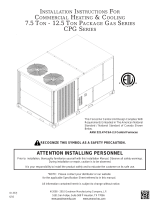
FIGURE 7C - Roof Curb
and Duct Opening
Dimensions
Dimensions - Downow
Roof Curb Option
CJ31 for MAPS
®
III & IV
Cabinet Sizes A, B, and
C
K


M

L
J

A
H
B
G



Supply Air Duct
Connection Size
C x D
Return Air
Duct Connection Size
E x F














Airflow
NOTES: Area enclosed by roof curb must comply with clearance to combustible materials. If the roof is constructed of
combustible materials, area within the roof curb must be ventilated, left open, or covered with non-combustible material
which has an "R" value of at least 5. If area within curb is left open, higher radiated sound levels may result.
If area inside curb is open, roof opening dimensions MUST be no greater than: Cabinet A - 34-13/16"x69"
(884x1753mm); Cabinet B - 49-13/16"x69" (1265x1753mm); Cabinet C - 61-5/16"x97-7/8" (1557x2486mm).
When cutting only duct openings, cut opening 1" (25mm) larger than duct size to allow clearance for installation.
Top View
Cabinet
Size
RCB or RCC
Model Size
RDB or RDC
Model Size
Illustration Codes - FIGURE 7C
A B C D E F G H J K L M
Curb Dimensions for Cooling Only Model RCB, RCC, RDB, RDC by Cabinet Size, Model Size - inches (±1/8)
A 060, 078, 090, 118, 120, 136 084, 102, 114, 142, 144, 162 6-1/8 26-1/2 24 12 24 12 38-5/8 13-1/4 17-1/2 12-7/8 72-3/4 12-1/4
B 160, 186, 200 184, 196, 210, 222, 224, 236, 257 N/A N/A 36 12 36 12 53-5/8 13-1/4 17-1/2 12-7/8 72-3/4 12-1/4
C
190, 216 248, 262, 272, 288 19-3/8 32-3/8 30 18 45 15 65-1/8 20-1/4 24-3/4 17-7/8 101-5/8 13-1/4
298, 410 354, 370, 468, 482 10-3/4 49-1/2 47 18 45 15 65-1/8 20-1/4 24-3/4 17-7/8 101-5/8 13-1/4
Curb Dimensions for Cooling Only Model RCB, RCC, RDB, RDC by Cabinet Size and Model Size - mm (±3)
A 060, 078, 090, 118, 120, 136 084, 102, 114, 142, 144, 162 156 673 610 305 610 305 981 337 445 327 1848 311
B 160, 186, 200 184, 196, 210, 222, 224, 236, 257 N/A N/A 914 305 914 305 1362 337 445 327 1848 311
C
190, 216 248, 262, 272, 288 492 822 762 457 1143 381 1654 514 629 454 2581 337
298, 410 354, 370, 468, 482 273 1257 1194 457 1143 381 1654 514 629 454 2581 337
Cabinet
Size
RDCB or RDCC
Model Size
RDDB or RDDC
Model Size
Gas Heat
Size *
Illustration Codes - FIGURE 7C
A B C D E F G H J K L M
Curb Dimensions for Cooling/Gas Heat Makeup Air Model RDCB, RDCC, RDDB, RDDC by Cabinet Size & Model Size - inches (±1/8)
A
060, 078, 090, 118,
120, 136
084, 102, 114, 142, 144 100 9-7/8 19 18 12 24 12 38-5/8 13-1/4 17-1/2 12-7/8 72-3/4 12-1/4
084, 102, 114, 142, 144, 162
150 6-1/8 26-1/2 24 12 24 12 38-5/8 13-1/4 17-1/2 12-7/8 72-3/4 12-1/4
200 N/A N/A 24 12 24 12 38-5/8 13-1/4 17-1/2 12-7/8 72-3/4 12-1/4
B
078, 090, 118, 136,
160, 186, 200
102, 114, 142, 162, 184, 196,
210, 222, 224, 236, 257
250 6-1/8 41-1/2 36 12 36 12 53-5/8 13-1/4 17-1/2 12-7/8 72-3/4 12-1/4
300 N/A N/A 36 12 36 12 53-5/8 13-1/4 17-1/2 12-7/8 72-3/4 12-1/4
C 190, 216, 298, 410
248, 262, 272, 284, 354, 370,
468, 482
400 19-3/8 32-3/8 30 18 45 15 65-1/8 20-1/4 24-3/4 17-7/8 101-5/8 13-1/4
500 13-1/4 44-1/2 42 18 45 15 65-1/8 20-1/4 24-3/4 17-7/8 101-5/8 13-1/4
600 10-3/4 49-1/2 47 18 45 15 65-1/8 20-1/4 24-3/4 17-7/8 101-5/8 13-1/4
700 8-1/4 55 52 18 45 15 65-1/8 20-1/4 24-3/4 17-7/8 101-5/8 13-1/4
Curb Dimensions for Cooling/Gas Heat Makeup Air Model RDCB, RDCC, RDDB,RDDC by Cabinet Size and Model Size - mm (±3)
A
060, 078, 090, 118,
120, 136
084, 102, 114, 142, 144 100 251 483 457 305 610 305 981 337 445 327 1848 311
084, 102, 114, 142, 144, 162
150 156 673 610 305 610 305 981 337 445 327 1848 311
200 N/A N/A 610 305 610 305 981 337 445 327 1848 311
B
078, 090, 118, 136,
160, 186, 200
102, 114, 142, 162, 184, 196,
210, 222, 224, 236, 257
250 156 1054 914 305 914 305 1362 337 445 327 1848 311
300 N/A N/A 914 305 914 305 1362 337 445 327 1848 311
C 190, 216, 298, 410
248, 262, 272, 284, 354, 370,
468, 482
400 492 822 762 457 1143 381 1654 514 629 454 2581 337
500 337 1130 1067 457 1143 381 1654 514 629 454 2581 337
600 273 1257 1194 457 1143 381 1654 514 629 454 2581 337
700 210 1397 1321 457 1143 381 1654 514 629 454 2581 337
NOTE: See pages 71-72 for
cross-reference by Model
Size and Cabinet Size.
Cabinet
Size*
RECB, RECC Model Size * REDB, REDC Model Size *
* Electric
Heat Size
Illustration Codes - FIGURE 7C
A B C D E F G H J K L M
Curb Dimensions for Cooling/Electric Heat Makeup Air Model RECB, RECC, REDB, REDC by Cabinet Size and Model Size - inches (±1/8)
A 060, 078, 090, 118, 120, 136 084, 102, 114, 142, 144, 162
All
available
N/A N/A 24 12 24 12 38-5/8 13-1/4 17-1/2 12-7/8 72-3/4 12-1/4
B
078, 090, 118, 120, 136, 160,
186, 200
084, 102, 114, 142, 144, 162, 184, 196,
210, 222, 224, 236, 257
N/A N/A 36 12 36 12 53-5/8 13-1/4 17-1/2 12-7/8 72-3/4 12-1/4
C 190, 216, 298, 410 248, 262, 272, 288, 354, 370, 468, 482 10-3/4 49-1/2 47 18 45 15 65-1/8 20-1/4 24-3/4 17-7/8 101-5/8 13-1/4
Curb Dimensions for Cooling/Electric Heat Makeup Air Model RECB, RECC, REDB, REDC by Cabinet Size and Model Size - mm (±3)
A 060, 078, 090, 118, 120, 136 084, 102, 114, 142, 144, 162
All
available
N/A N/A 610 305 610 305 981 337 445 327 1848 311
B
078, 090, 118, 120, 136, 160,
186, 200
084, 102, 114, 142, 144, 162, 184, 196,
210, 222, 224, 236, 257
N/A N/A 914 305 914 305 1362 337 445 327 1848 311
C 190, 216, 298, 410 248, 262, 272, 288, 354, 370, 468, 482 273 1257 1194 457 1143 381 1654 514 629 454 2581 337
Form I-MAPSIII&IV, Page 14
5.4.1.2 Roof Curb for MAPS
®
III&IV A, B, and C Cabinet with Vertical (Down) Airow WITH an
Optional Energy Recovery Module, Option ER1A, ER1B, ER1C (Roof Curb Option CJ34)
Roof Curb P/N by Model/Size
See Model
Size / Cabinet
Size Cross
Reference on
pages 71-72.
Cabinet A Cabinet B Cabinet C
RCB/RCC/RDB/RDC w/Option ER1 - All Cabinet A - - All Cabinet B
190, 216, 248,
262, 272, 288
-
298, 410, 354,
370, 468, 482
-
RDCB/RDCC/RDDB/RDDC w/Opt ER1 100 150 200 250 300 400 500 600 700
RECB/REDB/RECC/REDC w/Opt ER1 - All Cabinet A - - All Cabinet B - - All Cabinet C -
Roof Curb (Option CJ34) Package P/N 262478 262479 262480 262481 262482 262483 262484 262485 262486
Code (FIGURE 8A) Component Description: Qty Component P/N's
A Curb Ends (unit & ER end) 2 204486 204487 208799
B Curb Sides (under unit) 2 204485 208798
C1 Supply Air Duct End 1 204431 204432 207961 207960 207959 207958
C2 Supply Air Duct End 1 204431 204432 207965 207964 207963 207962
D1 Supply Air Duct Side 1 204433 204434 204436 204435 204437 207967
D2 Supply Air Duct Side 1 204433 204434 204436 204435 204437 207967 207971
E Return Duct End 1 204438 204439 207966
F Return Duct Side 1 204440 204441 207974
G Return Duct Side Angle 1 204444 207973
H Return Duct Rear Angle 1 204442 204443 207972
J Curb End (unit end in center) 1 261995 261996 260855
K Tunnel (between unit & ER) 1 261993 261994 260856
L Right Curb Side (under ER) 1 262411 262418
M Left Curb Side (under ER) 1 262412 262419
FIGURE 8A - Roof Curb Components and Layout
for MAPS
®
Cabinets A, B, and C with Energy
Recovery Option ER1
NOTES:
Curb in FIGURE 8A applies to a MAPS
®
unit with an optional
energy recovery module. For downow curb without an
energy recovery module (Option CJ31), go to Paragraph
5.4.1.1 page 11.
All curbs include corner hardware as listed below and
screws for attaching duct pieces.
Integral ducts are designed so that ductwork may be either
inserted down from the top or attached from the bottom.
Apply sealant tape to tops of supply air "dividers" (C & D)
that mate with the blower or heat exchanger opening.
Apply sealant tape to tops of return air "dividers" (E, F, G, H).
Apply sealant tape to tops of all curb rails.
Curb MUST be level.
5.4 Mounting on a Roof Curb (cont'd)
5.0 Mounting
(cont'd)
5.4.1 Downow Roof Curbs for MAPS
®
III Cabinets A, B, C (cont'd)
Option CJ34 Roof Curb Corner Hardware (See FIGURE 8B)
For Top Two
"Holes"
(16) 5/16" x 1" Lag Screws, P/N 16243; (16) 5/16" Lockwasher, P/N 1333
For Bottom
Two "Holes"
(16) 5/16" x 3/4" Hex Head Cap Screw, P/N 16247; (16) 5/16" Lockwasher, P/N 1333;
(16) 5/16-18 Hex Nut, P/N 1035
Hardware to Assemble and Attach Dividers to make Duct Connections and Sealant Tape for Top
of Rails: (75) #10 Sheetmetal Screws, P/N 11813; (1) 1/4" x 1-1/4" x 50' Foam Sealant Tape,
P/N 66302
Installation Instructions
for Down Discharge
Roof Curb, Option
CJ34, for MAPS
®
Cabinet Sizes A, B,
and C WITH Energy
Recovery Module,
Option ER1
1. Assemble the MAPS
®
Unit Curb Section
a) Position the ends and sides (Codes B, B, A, and J) of the MAPS
®
unit section
of the curb as shown in the drawing in FIGURE 8A. Fasten with bolts and lag
screws as illustrated in the corner detail (FIGURE 8B).
b) Install bottom opening ductwork. Use the sheetmetal screws to attach the
dividers (Codes C1, C2, D1, D2, E, & F). Attach the return air duct angles
(Codes G & H) to the attached end and side and to the roof curb. NOTE: If the
system does not have a return air opening, Codes F, G, & H may be installed in
the curb but are not required.
Form I-MAPSIII&IV, P/N 222917R9, Page 15
6. Before placing the MAPS
®
unit or energy recovery module on the curb:
If ductwork is being installed from the top, slide the ductwork down into the discharge and return air openings.
Ductwork should be sized slightly smaller with a minimum 3/4" duct ange that will rest on and be attached to all
sides of the duct connection. See Paragraph 6.4 for ductwork requirements.
Apply 1/4" x 1-1/4" foam sealant tape to both the top surface of the curb rails and the top surface of the perimeter of
the integral dividers, being sure to make good butt joints at all corners. The sealant tape must be applied to prevent
water leakage into the curb area due to blown rain and capillary action.
7. Lift the MAPS
®
unit on to the prepared curb (See Rigging and Lifting in Paragraph 5.5). IMPORTANT: Verify that the
unit will be placed in the correct airow orientation to mate properly with the discharge and return air openings.
8. After the MAPS
®
unit is in place, follow the instructions shipped with the energy recovery module
(Form I-MAPSIII&IV-ER) to lift and mate the energy recovery module to the MAPS
®
unit.
















Curb Detail
Corner Detail
Curb Section
FIGURE 8B - Option
CJ34 Downow Roof
Curb Cross Section and
Corner Detail
MUST be sealed
between curb cap
and top of curb
Cabinet
2x4 Wood Nailer
Counter Flashing
(by installer)
Cant Strip
(by installer)
Weld, bolt, or lag screw curb to deck structure.
Roofing Felts
(by others)
Insulation
2. Assemble the Energy Recovery Curb Section
a) Position the sides (Codes L and M) as shown in the drawing in FIGURE 8A.
Attach the sides to the assembled curb section with sheetmetal screws.
b) Attach the curb end (Code A). Fasten with bolts and lag screws as illustrated in
the corner detail (FIGURE 8B) .
c) Position the tunnel (Code K) over the opening in the center. Attach with
sheetmetal screws.
3. Check the roof curb for squareness. The curb must be adjusted so that the
diagonal measurements are equal within a tolerance of ±1/8” (±3mm).
4. Level the roof curb. To ensure a good weatherproof seal between the unit curb cap
and the roof curb, the roof curb must be leveled in both directions with no twist end
to end. Shim as required and secure curb to the roof deck before installing ashing
(See Curb Detail in FIGURE 8B).
5. Install eld-supplied ashing.
FIGURE 8C - Curb Dimensions of Option CJ34 for a MAPS
®
unit with
Option ER1
Curb Section for
Energy Recovery
Module
Curb Section for MAPS® Unit (Cabinet A, B, or C)
Supply Air Duct
Connection Size
Same as CxD on
pages 4 and 5.
Return Air Duct Connection
Size Same as ExF on
pages 4 and 5.
Duct Dimensions for
the MAPS® unit are
the same as without
the Energy Recovery
Module.
See dimensions
A, B, C, D, E, F, H, J,
K, M on pages 4-5.
TOP VIEW - Option CJ34 Roof Curb for MAPS® Cabinet Sizes* A, B, or C with Option ER1, Energy Recovery Module
X
Y
* See pages
71-72 for cross-
reference by
Cabinet &
Model.
Dimensions and
Weights
See Table on
next page
for X and Y
Dimensions.
Form I-MAPSIII&IV, Page 16
Cabinet
Size
RCB/RCC Model Size RDB/RDC Model Size
Codes - FIG 8C
X Y
Outside Curb Dimensions for Cooling Models RCB/RCC/RDB/RDC with Energy Recovery
Module by Cabinet Size, Model Size - inches (±1/8)
A
060, 078, 090, 118, 120, 136 084, 102, 114, 142, 144, 162 38-5/8 136-3/4
B
160, 186, 200 184, 196, 210, 222, 224, 236, 257 53-5/8 136-3/4
C
190, 216 248, 262, 272, 288 65-1/8 171-5/8
298, 410 354, 370, 468, 482 65-1/8 171-5/8
Outside Curb Dimensions for Cooling Models RCB/RCC/RDB/RDC with Energy Recovery
Module by Cabinet Size, Model Size - mm (±3)
A
060, 078, 090, 118, 120, 136 084, 102, 114, 142, 144, 162 981 3473
B
160, 186, 200 184, 196, 210, 222, 224, 236, 257 1362 3473
C
190, 216 248, 262, 272, 288 1654 4359
298, 410 354, 370, 468, 482 1654 4359
Cabinet
Size *
RDCB/RDCC
Model Size*
RDDB/RDDC Model Size*
Gas Heat
Size *
Codes - FIG 8C
X Y
Curb Dimensions for Cooling/Gas Heat Makeup Air Model RDCB, RDCC, RDDB, RDDC with
Energy Recovery Module by Cabinet Size and Model Size - inches (±1/8)
A
060, 078, 090, 118,
120, 136
084, 102, 114, 142 100 38-5/8 136-3/4
084, 102, 114, 142, 144, 162
150 38-5/8 136-3/4
200 38-5/8 136-3/4
B
078, 090, 118, 120,
136, 160, 186, 200
102, 114, 142, 144, 162, 184,
196, 210, 222, 224, 236, 257
250 53-5/8 136-3/4
300 53-5/8 136-3/4
C
190, 216, 298, 410
248, 262, 272, 284, 354, 370,
468, 482
400 65-1/8 171-5/8
500 65-1/8 171-5/8
600 65-1/8 171-5/8
700 65-1/8 171-5/8
Curb Dimensions for Cooling/Gas Heat Makeup Air Model RDCB, RDCC, RDDB, RDDC with
Energy Recovery Module by Cabinet Size and Model Size - mm (±3)
A
060, 078, 090, 118,
120, 136
084, 102, 114, 142 100 981 3473
084, 102, 114, 142, 144, 162
150 981 3473
200 981 3473
B
078, 090, 118, 120,
136, 160, 186, 200
102, 114, 142, 144, 162, 184,
196, 210, 222, 224, 236, 257
250 1362 3473
300 1362 3473
C
190, 216, 298, 410
248, 262, 272, 284, 354, 370,
468, 482
400 1654 4359
500 1654 4359
600 1654 4359
700 1654 4359
Cabinet
Size*
RECB/RECC
Model Size *
REDB/REDC Model
Size *
* Electric
Heat Size
Codes - FIGURE 8C
X Y
Curb Dimensions for Cooling/Electric Heat Makeup Air Model RECB, RECC, REDB, REDC
by Cabinet Size and Model Size - inches (±1/8)
A
060, 078, 090, 118,
120, 136
084, 102, 114, 142,
144, 162
All
available
38-5/8 136-3/4
B
078, 090, 118, 120,
136, 160, 186, 200
084, 102, 114, 142, 144,
162, 184, 196, 210, 222,
224, 236, 257
53-5/8 136-3/4
C
190, 216, 298,
410
248, 262, 272, 288,
354, 370, 468, 482
65-1/8 171-5/8
Curb Dimensions for Cooling/Electric Heat Makeup Air Model RECB, RECC, REDB, REDC
by Cabinet Size and Model Size - mm (±3)
A
060, 078, 090, 118,
120, 136
084, 102, 114, 142,
144, 162
All
available
981 3473
B
078, 090, 118, 120,
136, 160, 186, 200
084, 102, 114, 142, 144,
162, 184, 196, 210, 222,
224, 236, 257
1362 3473
C
190, 216, 298,
410
248, 262, 272, 288,
354, 370, 468, 482
1654 4359
5.4.1.2 Roof Curb Option CJ34 for MAPS
®
III&IV, Cabinets A, B, & C with ER Module (cont'd)
5.4 Mounting on a Roof Curb (cont'd)
5.0 Mounting
(cont'd)
5.4.1 Downow Roof Curbs for MAPS
®
III Cabinets A, B, C (cont'd)
Option CJ50 is a 32" (813mm) high horizontal airow curb for MAPS
®
III&IV, Cabinet
Sizes A and B. Option CJ49 is a 36" (914mm) high horizontal airow curb for MAPS
®
III
&IV, Cabinet Size C.
Option CJ54 is a 32" (813mm) high horizontal airow curb for MAPS
®
III&IV, Cabinet
Sizes A and B with an energy recovery module. Option CJ53 is a 36" (914mm) high
horizontal airow curb for MAPS
®
III&IV, Size C with an energy recovery module.
Verify all the components and be sure that the curb is correct for the system being
installed.
5.4.2 Roof Curbs for
Horizontal Airow
(Options CJ49, CJ50,
CJ53, and CJ54) -
Cabinets A, B, and C
NOTE: Horizontal ow curbs
in this section do not apply
to a MAPS
®
unit with an
optional energy recovery
module. For a horizontal
airow curb for a MAPS
®
unit with an energy recovery
module (Option ER1), go to
Paragraph 5.4.2.2 page 19.
Components and Application
If area inside curb is open, roof opening dimensions
MUST be no greater than:
Cabinet A - 34-13/16"x133" (884x3378mm);
Cabinet B - 49-13/16"x133" (1265x3378mm);
Cabinet C - 61-5/16"x167-7/8" (1557x4264mm).
When cutting only duct openings, cut opening 1" (25mm)
larger than duct size to allow clearance for installation.
Approximate Weights of
Roof Curb Option CJ34
by Cabinet Size *
Cabinet
A
Cabinet
B
Cabinet
C
lbs 254 292 365
kg 115 132 166
*See Model Size / Cabinet Size Cross Reference on pages 71-72.
5.4.2.1 Horizontal
Airow Roof Curb
Option CJ49 for
MAPS
®
III&IV Cabinets
A, & B and Option CJ50
for Cabinet C
Roof Curb P/N's by Model & Cabinet Size * Cabinet A Cabinet B Cabinet C
Models RCB/RCC/RDB/RDC *All Sizes *All Sizes *All Sizes
Models RDCB/RDCC/RDDB/RDDC with Cabinet
& Gas Heat Size Combination
With Gas Heat
Sizes 100/150/200
With Gas Heat
Sizes 250/300
With Gas Heat Sizes
400/500/600/700/1000
Models RECB/RECC/REDB/REDC *All Sizes *All Sizes *All Sizes
ID on
Part
Roof Curb Package P/N (Option) 261699 (CJ50) 261700 (CJ50) 261701 (CJ49)
Component Descriptions Qty Component P/N's
A Curb End Assembly (solid)
1
261653 261654 261670
B Curb Side Assembly (insulated)
2
261655 261671
3 C's
Curb End Assembly (insulated)
1
261656 261657 261672
Duct Flanges (4pcs in one bundle)
4
261386 261387 261414
Return Air Cap (not used with return air)
1
261388 261389 261415
D Supply Duct End (solid insulated partition)
1
261658 261659 261673
E Supply Duct Bottom (insulated) (**2 pcs)
**1
261660 261661 ** 261674 & 261428
F Supply Air Duct Bottom Liner (**2 pcs)
**1
261394 261395 ** 261418 & 261429
G Air Bafe ("curve" in the supply duct)
1
268604 268605 268606
H Supply Air Duct Center Divider
1
261396 261397 261419
J Return Air Duct Partition
1
261662 261663 261675
K
Vertical Divider (lower part) between
Supply and Return Air Ducts
1
261666 261677
Form I-MAPSIII&IV, P/N 222917R9, Page 17
Assembly and
Installation Instructions
for Option CJ49
and CJ50, Curbs for
Horizontal Airow
Counter
Flashing
(by installer;
install after
curb assembly)
Insulation
2 x 4 Wood
Nailer
Cabinet
Cant Strip
(by installer)
Weld, bolt,
or lag screw
curb to deck
structure.
1” Lag Screw and
Lockwasher
(1 per corner)
(4 per corner) 3/4” Hex Head
Cap Screws with Lockwashers
and Hex Nuts
A
B
B
Return
Air
Cap
3 C’s
FIGURE 9A - Assemble Curb Ends (A&C) and
Curb Sides (B&B)
3. Check the assembly for squareness. The curb must be adjusted so that the
diagonal measurements are equal within a tolerance of ±1/8” (±3mm).
4. Level the roof curb. To ensure a good weatherproof seal between the unit curb
cap and the roof curb, the roof curb must be leveled in both directions with no twist
end to end. Shim as required and secure curb to roof deck. (NOTE: Install internal
ducts before ashing; see Step 5.)
5. Install solid partition (Code D), duct bottom (Codes E & F), and air bafe (Code
G) using sheetmetal screws (See FIGURE 9C).
a) Position the solid partition (Code D) with insulation side toward the solid end
of the curb. Align the holes (push the insulation out of the way) and attach
partition to curb sides (B & B).
b) Position insulated duct bottom (Code E) with insulation side up in the bottom
of curb. Align the holes (push the insulation out of the way) and attach
partition to curb sides (B & B). Attach the bottom to partition (D).
c) Position the bottom liner (Code F) over the insulation in the bottom of the
curb. Align the holes and attach around the perimeter.
d) Position the air bafe (Code G) against the partition (D). Align the holes and
attach. Align the air bafe with the holes in the bottom liner (F) and attach.
FIGURE 9B -
Curb Detail
CAUTION: Before
installation, recheck to
be sure that the curb
selected matches the
unit ordered. Verify
the dimensions of the
curb received with the
dimensions on page 19.
ID Description (cont'd)
Qty
Component P/N's (cont'd)
L
Divider (upper part) between Supply
and Return Air Ducts
1
261667 261668 261678
M Duct Divider Top Liner
1
261408 261409 261426
N Duct Divider Bottom Liner
1
261405 261424
P Supply Air Duct Large Top (insulated)
1
261664 261665 261676
Q Supply Air Duct Small Top (insulated)
1
261669 261679
Hardware Bag
1
262438 (see content list, left below)
* See Model Size / Cabinet Size Cross Reference on page 2. ** Curb bottom in Cabinet C is 2-piece.
A
B
B
C
D
E
D
F
D
E
A
A
B
B
Install D and E
(See NOTE).
Install F
(See
NOTE).
B
A
D
F
B
G
Install
G.
FIGURE 9C - Install Supply
Duct Partition (D), Bottom
(E), Bottom Liner (F), and Air
Bafe (G)
NOTE: Cabinet C - Insulated bottom
(Code E) and Bottom Liner (Code F)
are two piece.
Insulation NOTE: There is no exposed insulation in the ducts.
All insulation in airow paths is covered with a liner.
1. Follow the Steps and refer to the curb assembly drawings
2. Position curb ends (Codes A & "large" C) and curb side rails (Codes B & B) as
shown in FIGURE 9A. Join the corners as illustrated.
Locate the 4-pc bundle labeled (C). Using sheetmetal screws from the hardware
package, attach the duct ange pieces to both the inlet and return air openings.
If not using return air in the installation, position the return air cap (C) over the
opening and attach. If a return air duct will be used, the cap is not needed.
Assy Hardware Bag, P/N 262438:
P/N Description Qty
1035 Nut 5/16" Hex-18 Thread 16
1333 Lockwasher 5/16 In. 20
16243
Hex Hd Lag Bolt 5/16” x
1-1/4”
4
16247 Cap Screw 5/16 X 3/4" 16
11813
S/M Screw #10-16x1/2
Ab Stalgd
125
66302 1-1/4x1/4 x 50 ft Sealant Tape
ID P/N by Cabinet Size
A A-261653 B-261654 C-261670
B A&B-261655 C-261671
C
A-261656 B-261657 C-261672
A-
261386
B-261387 C-261414
A-261388 B-261389 C-261415
ID P/N by Cabinet Size
D A-261658 B-261659 C-261673
E A-261660 B-261661 C-261674 & 261428
F A-261394 B-261395 C-261418 & 261429
G A-268604 B-268605 C-268606
Form I-MAPSIII&IV, Page 18
6. Install supply air duct partition (Code H) and return air duct
partition (Code J) using sheetmetal screws. (See FIGURE 9D).
a) Position partition (Code H) in the orientation illustrated. Align
the holes and attach the partition to curb sides (B & B) and
bottom liner (F).
b) Position partition (Code J) in the orientation illustrated. Align
the holes and attach the partition to curb sides (B & B) and
bottom liner (F).
7. Install supply air and return duct dividers (Code K) and (Code L);
divider liners (Code M) and (Code N); and duct tops (Code P)
and (Code Q) using sheetmetal screws. (See FIGURE 9E).
a) Position and attach duct dividers (Codes K & L) as illustrated.
Cover the insulation with liners (Codes M & N) and attach with
screws.
b) Position tops (Codes P & Q) with insulation side up. Align
the holes (push the insulation out of the way) and attach the
perimeter.
8. Install eld-supplied ashing (FIGURE 9B, page 17).
A
B
B
D
F
C
H
F
C
B
B
J
J
G
FIGURE 9D - Install the Large Duct
Partitions (H&J)
B
M
N
P
Q
K
L
B
L
K
C
C
And
corresponding
liners (M & N).
Install duct
tops (P & Q).
(insulation
side)
B
B
Install
insulated
dividers
(K & L)
FIGURE 9E - Install Smaller
Duct Partitions and Liners
(K, L, M, N) and Duct Tops
(P&Q)
9. Before placing the MAPS
®
unit or optional duct furnace
on the curb:
Apply 1/4" x 1-1/4" foam sealant tape to both the top
surface of the curb rails and the top surface of the perimeter
of the duct dividers, being sure to make good butt joints at
all corners.
If installing an optional duct furnace curb section (Option
JH), place it on the curb before the unit. See Paragraph
5.4.3.
When it is time to lift the MAPS
®
unit or optional duct
furnace onto the prepared curb (See Rigging and Lifting,
Paragraph 5.5.), be sure that all of the above preparations
have been made. MPORTANT: Verify that the unit will be
placed in the correct airow orientation to mate properly
with the discharge and return air openings. Remember that
the INLET AIR END OF THE UNIT is at the DISCHARGE
(duct connection) END OF THE CURB.




















5.4 Mounting on a Roof Curb (cont'd)
5.0 Mounting
(cont'd)
5.4.2 Roof Curbs for Horizontal Airow - Cabinets A, B, C (cont'd)
5.4.2.1 Horizontal Airow Roof Curb Options CJ49 and CJ50 (cont'd)
Assembly and Installation Instructions (cont'd)
ID P/N by Cabinet Size
H A-261396 B-261397 C-261419
J A-261662 B-261663 C-261675
ID P/N by Cabinet Size
K A&B-261666 C-261677
L A-261667 B-261668 C-261678
M A-261408 B-261409 C-261426
N A&B-261405 C-261424
P A-261664 B-261665 C-261676
Q A&B-261669 C-261679
FIGURE 9F - Airow through the Curb
Form I-MAPSIII&IV, P/N 222917R9, Page 19
FIGURE 9G - Dimensions and Weights
- Options CJ49 and CJ50 for MAPS
®
Cabinets A, B, and C without an Energy
Recovery Module
Dimensions and Weight
R
S
T
U
V
W
X
Y
TOP
VIEW
SIDE
VIEW
Supply
Duct
Supply
Duct
Return Air
Duct
R
10-3/16
(259)
5.4.2.2 Roof Curbs
for Horizontal Airow
(Options CJ54 and
CJ53) for MAPS
®
III&IV
Cabinets A, B, and
C WITH an Energy
Recovery Module
Components and Application
*See Model Size / Cabinet Size
Cross Reference on pages
71-72.
Cabinet R S T U V W X Y Wt
A*
inches
15 2-5/16
34-13
/16 38-5/8 18 32 69 72-3/4 353 lbs
mm
381 59 884 981 457 813 1753 1848 160 kg
B*
inches
22-1/2 2-5/16
49-13
/16 53-5/8 18 32 69 72-3/4 434 lbs
mm
572 59 1265 1362 457 813 1753 1848 197 kg
C*
inches
28-1/4 2-5/8 61-5/16 65-1/8 22 36 97-7/8 101-5/8 654 lbs
mm
718 67 1557 1654 559 914 2486 2581 297 kg
*See Model Size / Cabinet Size Cross Reference on pages 71-72.
NOTE: Curbs in this section
do not apply to a MAPS
®
unit without an optional
energy recovery module.
For a horizontal airow curb
for a MAPS
®
unit without an
energy recovery module),
go to Paragraph 5.4.2.1,
page 16.
CAUTION: Before
installation, recheck
to be sure that the
correct curb has been
ordered. Be sure that
the curb selected
matches the unit
ordered. Verify the
dimensions of the
curb received with the
dimension table on
page 22.
Roof Curb P/N's by Model & Cabinet Size *
Cabinet A
Cabinet B Cabinet C
Models RCB/RCC/RDB/RDC
*All Sizes *All Sizes *All Sizes
Models RDCB/RDCC/RDDB/RDDC with
Cabinet & Gas Heat Size Combination
With Gas Heat
Sizes 100/150/200
With Gas Heat
Sizes 250/300
With Gas Heat Sizes
400/500/600/700/1000
Models RECB/RECC/REDB/REDC
*All Sizes *All Sizes *All Sizes
ID on
Part
Roof Curb Package P/N (Option)
262533 (CJ54) 262534 (CJ54) 262535 (CJ53)
Component Description: Qty Component P/N's
A
Curb End Assembly (solid w/insulation) 1 261653 261654 261670
B
Curb Side Assembly (insulated) 2 261655 261671
C
Supply Duct End (solid insulated partition) 1 261658 261659 261673
D
Supply Duct Bottom (insulated) (** 2 pcs) **1 261660 261661 ** 261674 & 261428
E
Supply Air Duct Bottom Liner (** 2 pcs) **1 261394 261395 ** 261418 & 261429
F
Air Bafe ("curve" in the supply duct) 1 268604 268605 268606
G1
Supply Air Duct Center Divider 1 261396 261663 261419
G2
Return Air Duct Partition Assembly 1 261662 261663 261675
H
Vertical Divider (lower part) between
Supply and Return Air Ducts
1 261666 261677
J
Divider (upper part) between Supply and
Return Air Ducts
1 261667 261668 261678
K
Duct Divider Top Liner 1 261408 261409 261426
L
Duct Divider Bottom Liner 1 261405 261424
M
Supply Air Duct Large Top (insulated) 1 261664 261665 261676
N
Supply Air Duct Small Top (insulated) 1 261669 261679
P
Horizontal Curb End Connector to ER 1 261384 262425
Q
Liner Support 2 262538 262547 262428
R
Right Curb Side Assy (under ER Module) 1 262537 262427
S
Left Curb Side Assy (under ER Module) 1 262536 262426
T
Duct Bottom Assembly (insulated) (under
ER Module) (** 2 pieces)
**1 262539 ** 262548 & 262553 ** 261674 & 262429
U
Curb Tunnel (between unit & ER) 1 261993 261994 260856
V
Bottom Duct Liner (under ER) (** 2 pcs) **1 262541 262550 ** 261418 & 262430
W
Vertical Duct Divider (insulated) 1 262543 262431
X
Vertical Return Air Duct Liner 1 262544 262432
3 Y's
Curb End Assembly (insulated)
1
261656 261657 261672
Duct Flanges (4pcs in one bundle)
4
261386 261387 261414
Return Air Cap (not used with return air)
1
261388 261389 261415
Z
Duct Top Assembly (insulated) 1 262545 ** 262552 & 262556 ** 261676 & 262435
Hardware Bag 1 (see content list, page 11)
*See Model Size / Cabinet Size Cross Reference on page 2. ** Curb part is two-piece; one of each P/N is required.
Assembly and Installation Instructions for Option CJ54 and CJ53, Curbs
with Energy Recovery Module
1. Follow the Steps and refer to the curb assembly drawings
2. Position curb end (Code A) and curb side rails (Codes B & B) as shown in
FIGURE 10A. Join the two corners as illustrated.
Form I-MAPSIII&IV, Page 20
Assembly and Installation Instructions for Option CJ54 & CJ53, Curbs
with Energy Recovery Module (cont'd)
FIGURE 10A - Assemble Curb End (A), Curb Sides (B&B), Supply Duct End (C), Insulated Bottom
(D) Bottom Liner (E)
and Bafe (F)
FIGURE 10B - Install
Duct Partitions G1
and G2
Insulation NOTE: There is no
exposed insulation in the ducts.
All insulation in airow paths is
covered with a liner.
FIGURE 10C - Install Smaller Duct Partitions, Liners, and Tops
5.0 Mounting
(cont'd)
5.4.2.2 Roof Curbs for Horizontal Airow (Options CJ54 & CJ53) for
Cabinets A, B, and C WITH an Energy Recovery Module (cont'd)
5.4.2 Roof Curbs for
Horizontal Airow
- Cabinets A, B, C
(cont'd)
A
B
B
C
D
E
B
B
D
A
C
(8 per corner) 3/4” Hex Head Cap Screws
with Lockwashers and Hex Nuts
2” Lag Screw
& Lockwasher
(1 per corner)
NOTE: Cabinet C - insulated bottom (D) and
liner (E) are both two pieces.
(insulation up)
(liner)
F
4. Install supply air duct partition (Code G1) and
return air duct partition (Code G2) with sheet-
metal screws (FIGURE 10B).
a) Position partition (Code G1) in the orientation
illustrated. Align the holes and attach the
partition to curb sides (B & B) and bottom liner
(E).
b) Position partition (Code G2) in the orientation
illustrated. Align the holes and attach the
partition to curb sides (B & B) and bottom liner
(E).
A
B
B
C
E
G1
G2
F
K
J
H
L
B
B
G2
E
G1
M
N
(Insulation
side up)
B
G2
B
L
E
A
C
G1
K
F
5. Install supply air and return air
insulated duct dividers (Codes H
& J) ; divider liners (Codes K & L);
and duct tops (Codes M & N) using
sheetmetal screws (FIGURE 10C).
a) Position and attach duct dividers
(Codes H & J) as illustrated.
Cover the insulation with liners
(Codes K & L) and attach with
screws.
b) Position tops (Codes M & N)
with insulation side up. Align
the holes (push the insulation
out of the way) and attach the
perimeter.
Hardware Bag includes:
P/N Description Qty
1035 Nut 5/16" Hex-18 Thread 48
1333 Lockwasher 5/16 In. 60
16243
Hex Hd Lag Bolt 5/16" x
1-1/4"
12
16247 Cap Screw 5/16 x 3/4" 48
11813
S/M Screw #10-16x1/2 Ab
Stalgd
210
66302 1-1/4 x 1/4 x 50 ft Sealant Tape
ID P/N by Cabinet Size
A A-261653 B-261654 C-261670
B A&B-261655 C-261671
C A-261658 B-261659 C-261673
D A-261660 B-261661
C-261674
& 261428
E A-261394 B-261395
C-261418
& 261429
F A-268604 B-268605 C-268606
ID P/N by Cabinet Size
G1 A-261396 B-261663 C-261419
G2 A-261662 B-261663 C-261675
ID P/N by Cabinet Size
H A&B - 261666 C-261677
J A-261667 B-261668 C-261678
K A-261408 B-261409 C-261426
ID P/N by Cabinet Size
L A&B-261405 C-261424
M A-261664 B-261665 C-261676
N A&B-261669 C-261679
3. Install supply duct end (Code C) and bottom (Codes D & E).
a) Position the solid partition (Code C) with insulation side toward the solid end of
the curb. Align the holes (push the insulation out of the way) and attach partition
to curb sides (B & B).
b) Position the duct bottom (Code D) in the curb with insulation side up. Align the
holes (push the insulation out of the way) and attach partition to curb sides (B &
B). Attach the bottom (Code D) to the partition (C).
c) Position the bottom liner (Code E) over the insulation in the bottom of the curb.
Align the holes and attach around the perimeter.
d) Position the air bafe (Code F) against the partition (C). Align the holes and
attach. Align the air bafe with the holes in the bottom liner (E) and attach.
  • Page 1 1
  • Page 2 2
  • Page 3 3
  • Page 4 4
  • Page 5 5
  • Page 6 6
  • Page 7 7
  • Page 8 8
  • Page 9 9
  • Page 10 10
  • Page 11 11
  • Page 12 12
  • Page 13 13
  • Page 14 14
  • Page 15 15
  • Page 16 16
  • Page 17 17
  • Page 18 18
  • Page 19 19
  • Page 20 20
  • Page 21 21
  • Page 22 22
  • Page 23 23
  • Page 24 24
  • Page 25 25
  • Page 26 26
  • Page 27 27
  • Page 28 28
  • Page 29 29
  • Page 30 30
  • Page 31 31
  • Page 32 32
  • Page 33 33
  • Page 34 34
  • Page 35 35
  • Page 36 36
  • Page 37 37
  • Page 38 38
  • Page 39 39
  • Page 40 40
  • Page 41 41
  • Page 42 42
  • Page 43 43
  • Page 44 44
  • Page 45 45
  • Page 46 46
  • Page 47 47
  • Page 48 48
  • Page 49 49
  • Page 50 50
  • Page 51 51
  • Page 52 52
  • Page 53 53
  • Page 54 54
  • Page 55 55
  • Page 56 56
  • Page 57 57
  • Page 58 58
  • Page 59 59
  • Page 60 60
  • Page 61 61
  • Page 62 62
  • Page 63 63
  • Page 64 64
  • Page 65 65
  • Page 66 66
  • Page 67 67
  • Page 68 68
  • Page 69 69
  • Page 70 70
  • Page 71 71
  • Page 72 72
  • Page 73 73
  • Page 74 74
  • Page 75 75
  • Page 76 76

Reznor RECB Installation guide

Type
Installation guide

Ask a question and I''ll find the answer in the document

Finding information in a document is now easier with AI