Keston C36 Installation guide
- Category
- Water heaters & boilers
- Type
- Installation guide

C36 Combi
User, Installation and Servicing
Instructions
FAN POWERED HIGH EFFICIENCY
MODULATING DOMESTIC CONDENSING
GAS COMBINATION BOILER
CE/PI No. 86-CM-44
C36 Combi - GC No. 47-930-01
C36P Combi
–
GC No. 47
-
930
-
02
These instructions must be left either with the
user or next to the site gas meter.
Keston Heating
PO Box 103, National Avenue, Kingston Upon Hull, HU5 4JN
Tel. +44 (0) 1482 443005 Fax. +44 (0) 1482 467133
email : [email protected] web :
www.keston.co.uk
COMPLIANT WITH BUILDING REGULATION PART L1 & L2
SEDBUK A RATED
W D 3 8 8
i s s u e 5 - 2 0 1 1

CONTENTS
NB : These instructions are an integral part of the appliance. This document must be handed over to
the user on completion of the installation to ensure compliance with the Gas Safety (Installation
& Use) Regulations
Section Description
0 HANDLING INSTRUCTIONS
0.1 List of contents
0.2 Recommended handling procedure
1 USER INSTRUCTIONS
1.1 Introduction
1.2 Maintenance
1.3 Boiler Setup and Operation
1.4 Safety Information
2 GENERAL INSTRUCTION
2.1 Description
2.2 Boiler Schematic
2.3 Related Documents
2.4 Physical Data
2.5 Optional Accessories
2.6 Performance Data C36 Combi and C36P Combi
3 BOILER LOCATION
3.1 Dimensions & Minimum Clearances
3.2 Service Connections
3.3 Position
3.4 Electrical
3.5 Boiler Size Selection
3.6 Gas Supply
3.7 CH & DHW Water Systems
3.8 Flue System
3.9 Air Supply
3.10 Compartment Installation
3.11 Condensate Drainage
4 INSTALLATION OF THE BOILER
4.1 Wall Mounting Bracket
4.2 Mounting The Boiler
4.3 Assembly Practice
4.4 Installing Flue And Air Pipes
4.5 Condensate Drainage
4.6 Water System
4.7 Gas Supply
4.8 Electrical Supply
4.9 Exchanging A Boiler
5 COMMISSIONING OF THE BOILER
5.1 Initial Flushing
5.2 Gas Supply
5.3 Electrical Installation
5.4 LP Gas
5.5 Initial Firing
5.6 Hot Flushing
WD388/0/2004 The Keston C36 Combi & C36P Combi Boilers
Page : i

5.7 Combustion Testing
5.8 Checking The Gas Pressure
5.9 Timing The Gas Meter
5.10 Handing Over To The User
6 FAULT FINDING
6.1 Electrical Control Sequence
6.2 Normal Operation
6.3 Fault Modes
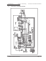
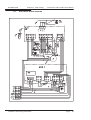
6.4 Functional Flow Wiring Diagram
6.5 Electrical Wiring Diagram
6.6 Illustrated Wiring Diagram
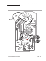
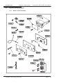
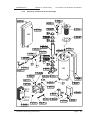
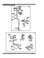
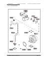
6.7 Exploded Assembly Diagrams
7 SERVICING
7.1 Pre Service Checks
7.2 Recommended Routine Service
8 REPLACEMENT OF PARTS
8.0 General
8.1 Precautions
8.2 Access
8.3 Replacement Procedure
8.4 Electrical Components
8.5 Spark Ignition/Flame Detection Electrode
8.6 Burner
8.7 Heat Exchanger
8.8 Condensate Trap
8.9 Pump
8.10 DHW Heat Exchanger
8.11 Expansion Vessel
9 SPARE PARTS LISTINGS
10 GAS BOILER COMMISSIONING CHECKLIST
WD388/0/2004 The Keston C36 Combi & C36P Combi Boilers
Page : ii

0. HANDLING INSTRUCTIONS
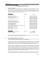
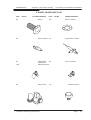
0.1 LIST OF CONTENTS
The Keston C36 Combi and C36P Combi are supplied almost totally pre-assembled. The units
use standard 50 mm muPVC (BS5255 and/or BSEN1566-1 and BSEN1329) pipe for the flue
and air intake systems. The boiler is packed in a single box without additional flue kit. All
additional components are packed inside the boiler cabinet itself. The following is a list of
components and their location in the boiler cabinet
Equipment List
Item Quantity Location
Wall Bracket Rawl Plugs 6 Inside accessories bag
Wall Bracket Wall Fixing Screws 6 Inside accessories bag
Wall Mounting Bracket 1 Secured to inside right
hand side of boiler case
Pre-Installation Jig Locator Cross 1 Secured to outside right
hand side of boiler case
Wall Mounting Bracket Nuts 1 Inside accessories bag.
Wall Mounting Bracket Washers 1+1 Inside accessories bag
50 mm muPVC Air/Flue Terminals 2 Inside accessories bag
Air Inlet Spigot (50 mm) 1 Inside accessories bag
Flue Outlet Spigot (50 mm) 1 Inside accessories bag
Air Inlet Spigot Gasket 1 Inside accessories bag
Air Inlet Spigot + Flue Outlet Spigot M6 Screws 4+2 Inside accessories bag
Cabinet Cable Entry Clamps 2 Inside accessories bag
Gas Isolating Cock with PTN 1 Inside accessories bag
Filling Loop Kit 1 Inside accessories bag
Outside Temperature Sensor 1 Inside accessories bag
Document List
Item Quantity Location
Boiler Warranty Registration Form 1 In document bag
Installation Template 1 In document bag
Remove the cabinet shell by removing the two retaining screws in the top of the cabinet and
the two retaining screws in the bottom of the cabinet.
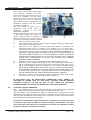
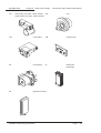
0.2 RECOMMENDED HANDLING PROCEDURE
NB : The following lift operation exceeds the recommended weight for a one-man lift as
specified in the Manual Handling Operations 1992 Regulations.
For the carriage of carton it is recommended at least two people perform any lift. Clear the
carriage route of the carton from point of delivery to point of installation. Take care to avoid trip
hazards, slippery or wet surfaces and when climbing steps and stairs. Always use assistance
if required. If a sack truck is used it is recommended the carton is strapped to the truck.
For the unpacking of the appliance from the carton, it is recommended at least two people
perform any lift. It is recommended to cut the base end of carton and open the carton flaps.
Ensure the protective packing over the boiler tappings at the base of the boiler is kept in place,
then tilt the boiler forwards from its back onto its base and remove carton by sliding up over
the boiler. When lifting this appliance the back should be kept straight at all times. Avoid
twisting at the waist - reposition the feet instead. Avoid upper body bending when holding the
appliance and keep the boiler as close to the body as possible.
Before hanging the appliance on the wall it is best to store the appliance laid on its back with
the casing on. When ready to hang the boiler on the wall remove the casing and place to one
WD388/0/2004 The Keston C36 Combi & C36P Combi Boilers
Page : iii

side. At this stage it is assumed that the wall bracket is correctly positioned and secured on
the wall face.
a) Have the wall bracket nut and washer to hand so that they can be accessed whilst holding
the boiler in position on its mounting bracket. If the optional pre-installation jig is not being
used discard the Pre-Installation Jig Locator Cross.
b) The boiler has a dry weight of 45 kg (99 lbs) and will therefore require at least two people
to lift without the use of lifting aids - ensure co-ordinated movements during lift. Always
use assistance if required.
c) Lift the boiler by gripping at the four corners of the boiler back plate. When lifting this
appliance the back should be kept straight at all times. Avoid twisting at the waist -
reposition the feet instead. Avoid upper body bending when holding the appliance and
keep the boiler as close to the body as possible.
d) Lift the boiler and locate onto the stud and the two pegs of the wall mounting bracket.
e) Place the wall mounting bracket washers over the bracket stud protruding through the
back plate of the boiler.
f) Secure the boiler onto the wall bracket by fixing the wall mounting bracket nut onto the
wall bracket stud. This must be tightened well.
Safety footwear and gloves are recommended PPE when lifting this appliance - to protect
against sharp edges and ensure good grip.
The C36 Combi and C36P Combi boilers can be fitted in compartments with very small
clearances required around the appliance (refer to Section 3.1). Due consideration should
therefore be given to access within the compartment for lifting and positioning.
A pre-installation jig plate (part no C.10C.0.11.00.0) with heating flow, heating return and cold
supply isolation is available as an optional accessory. This jig enables the installation of the
pipework to be carried out and pressure tested before hanging the boiler. Further instructions
for this procedure are included with the jig plate kit.
WD388/0/2004 The Keston C36 Combi & C36P Combi Boilers
Page : iv

1. USER INSTRUCTIONS
1.1 INTRODUCTION
Thank you for choosing this Keston C36 Combi for your household heating and hot water
needs. The boiler is designed to be very straightforward to operate and has no user
serviceable parts inside the cabinet. The following instructions are to provide you with
information on the operation and maintenance of your C36 Combi and what to do in the
unlikely event of a fault.
These user instructions should be read carefully to ensure safe and economical use of your
C36 Combi. The C36 Combi model is for use with natural gas only, the C36P Combi model is
for use with LPG only.
1.2 MAINTENANCE
Servicing
To ensure continual safe and efficient operation and to maintain product warranties it is a
requirement that the appliance is checked and serviced at least once per year. It is the law
that any servicing must be carried out by a competent person. Removal of the appliance
cabinet by anyone other than a competent person will automatically invalidate the
appliance warranty.
Clearances
If fixtures are to be positioned close to the boiler, the following minimum clearances must be
observed: Top 150mm, Left 5mm, Right 5mm, Base 100mm, Front 305mm. Extended
clearance is required to the front for servicing.
Cleaning
Normal case cleaning only requires dusting with a dry cloth. To remove more stubborn marks
wipe with a damp cloth and finish with a dry cloth.
1.3 BOILER SETUP & OPERATION
Check that the gas supply from the gas meter is turned on. Switch on the electrical supply to
the boiler. The display will now run through a self check procedure. Set any controls to call for
heat.
To light the boiler
The C36 Combi features separate adjustment of central heating and domestic hot water
temperature. To set these press the “+” or “-” buttons associated with the heating or hot water
temperature and set the required temperature. After a few seconds the display stop flashing
and will change back to show the actual boiler temperature.
If the actual temperature is less than the desired temperature the boiler will fire and, after a
few seconds, a “.” will appear in the lower right hand corner of the display to show that the
boiler is alight.
In summer you can
switch the boiler to hot
water only by pressing
the “Summer” button to
that the green lamp
above it is illuminated. In
this mode the boiler will
not respond to any
demand for central
heating. Press the
“Summer” button again
to extinguish the green
light above and resume
normal central heating
operation.
WD388/0/2004 Chapter 1 : User Instructions The Keston C36 Combi & C36P Combi Boilers
Boilers
Installation & Servicing Instructions Page : 1

Normal Operation
During normal operation the digital display will dhow the current boiler temperature and will
show a “.” In the lower right corner of the display when the burner is alight. If the green lamp
near the CH or DHW+ - keys is illuminated the boiler is receiving a demand for that function.
If the green lamp is flashing the boiler is either up to temperature or shutting down following
removal of the CH or DHW demand.
Fault Modes
In the event that the boiler detects a situation which it considers to be a fault the display will
change to show a flashing fault code starting with an “E” and then a two digit number. The
table below explains these codes and the action you should take.
Water pressure too high - You have put too much water pressure in your systemE40
Water pressure error - You must top up the water pressure for your systemE37
Mains supply frequency incorrect - There may be a problem with your power supply.E35
Mains supply voltage < 180V - There may be a problem with your power supplyE34
Flame drop out - Check for obstruction of the flue and/or air terminals,
blockage/freezing of the drain pipe or a low gas supply (LPG).
E26
Water pressure losses - You have topped up the water pressure more than 4 times in
24 hours. You may have a leak on the system..
E24
Boiler overheat - Check that any valves to the heating circuit have not been shut down,
that there is no air in the system and that the water pressure is correct..
E03
False flame - There is possibly a problem with the power supply.E02
Ignition failure - the boiler has attempted to light five times and not succeeded - check
the gas supply is on.
E01
Description of faultDisplay
The above is an abbreviate list of possible error codes. If the code is not in the list above
consult a GAS SAFE REGISTER registered engineer. A full list of codes can be found in
Chapter 6 of this manual. If a code appears and you feel the original cause has been rectified,
press the “Reset” button to resume boiler operation. If the code persists consult a GAS SAFE
REGISTER registered engineer.
When topping up the water pressure you can observe the actual pressure by pressing the
“Installer” button repeatedly until the number “5” appears. After a few seconds the display with
then change to show the system water pressure in bar. Set the water pressure to between 1.0
and 2.0 bar.
Precautions
Care must be taken at all times to ensure that no blockage or obstruction is present in the
condensate drainage line. In addition, the air intake and flue exhaust terminals must be free
from obstruction at all times.
Frost Protection
The C36 Combi has an integral frost protection function. However, care should also be taken
that any exposed pipework is adequately insulated to prevent freezing.
1.4 SAFETY INFORMATION
IF YOU SUSPECT A GAS LEAK TURN OFF THE APPLIANCE IMMEDIATELY, TURN OFF
THE GAS TAP TO THE APPLIANCE (LOCATED UNDERNEATH) AND CONTACT YOUR
LOCAL GAS REGION WITHOUT DELAY.
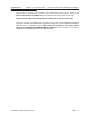
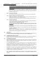
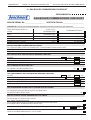
Benchmark Initiative
As part of the industry wide “Benchmark” initiative C36 Combi
boiler manual includes Gas Boiler Commissioning
Checklist (Chapter 10). This form should be completed by
WD388/0/2004 Chapter 1 : User Instructions The Keston C36 Combi & C36P Combi Boilers
Boilers
Installation & Servicing Instructions Page : 2

your installer at the end of the installation and commissioning process. The details of the
Checklist will be required in the event of any warranty work being required. There is also
Service Interval Record (Chapter 10) to be completed after each annual service visit.
These forms (Chapter 10) should be kept in a safe place for the life of the boiler.
The boiler should be installed and serviced only by GAS SAFE REGISTER registered
operatives. All GAS SAFE REGISTER registered Installers carry a GAS SAFE REGISTER ID
card and have a registration number. Both should be recorded in your boiler manual
(Chapter 10: GAS BOILER COMMISSIONING CHECKLIST). You can check your installer by
calling GAS SAFE REGISTER direct on 0800 408 5500.
WD388/0/2004 Chapter 1 : User Instructions The Keston C36 Combi & C36P Combi Boilers
Boilers
Installation & Servicing Instructions Page : 3

2. GENERAL INSTRUCTION
2.1 DESCRIPTION
The KESTON C36 Combi and C36P Combi combination boilers utilise the latest in
condensing technology to produce a high efficiency boilers that deliver an exceptional hot
water flow rate with SEDBUK A rated efficiency.
The C36 Combi and C36P Combi are unique in concept and design. They comprise a
high efficiency stainless steel heat exchanger coupled with a low emissions burner to
deliver ultra high efficiency condensing mode operation and a plate-to-plate heat
exchanger for domestic hot water production all within a compact wall hung cabinet. The
unit automatically adjusts gas and air rate according to demand to give a heating output in
the range of 7.4kW to 28.0kW [condensing]. The integral pump assembly is automatically
speed controlled to best match water flow rate to heat output & further increase appliance
efficiency. The efficient plate-to-plate heat exchanger provides superior levels of
performance: its has an outstanding hot water performance of 14.5 L/min (at 35C
temperature rise) and 17.0 L/min (at 30C temperature rise - EN625)
In addition, the boilers feature a connection for an optional outside sensor to enable the
boilers inbuilt weather compensation option which delivers enhanced user comfort levels
with peak operating efficiency due to the lower flow temperatures involved. The boiler also
features an “Opentherm” connection point for the Keston Room Control module which
provides further advanced user control for room temperature compensation and optimum
start. The boiler fascia provides separate user controls for central heating and domestic
hot water temperatures. The advanced hot water flow monitoring ensures exceptionally
stable hot water temperatures are provided. The boilers have the added advantage of very
high efficiency, and small diameter muPVC plastic flue which can be extended up to 20
metres horizontally or vertically.
The Keston C36 Combi uses a variable speed combustion blower to deliver a premix of
gas and air to a downward firing burner in a high efficiency, single pass heat exchanger.
The flue system is room sealed and fan powered. The ignition is direct spark and fully
automatic. The boiler housing is not waterproof and should be installed in a position
where it will always be dry. Combustion air is drawn from the cabinet which is connected
to outside atmosphere via a small diameter plastic intake pipe. The cabinet therefore
remains under negative pressure at all times the boiler is operating.
These boilers are designed for use as part of a sealed water central heating system with
fully pumped circulation. The pump, an 8l expansion vessel and associated safety devices
are all fitted within the boiler.
The boiler heat exchanger is made from highly corrosion resistant stainless steel in
corrugated pipe form which provides massive surface area within a compact dimension.
The hot combustion gases from the down firing burner pass around the stainless steel
pipes imparting heat into the system water. The integral variable speed pump within the
appliance cabinet ensures the heat exchanger receives correct water flow when firing.
The C36 Combi is not a high water content boiler and does not contain the metal mass, or
water volume, of a cast iron or steel boiler. This boiler is of low mass and low water
content and therefore responds faster when there is a call for heat. The C36 Combi
features full user diagnostics, integral frost protection function, automatic pump and fan
exercise in periods of inactivity, anti cycle control and dry fire protection.
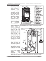
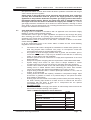
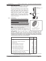
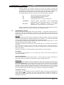
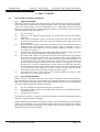
2.2 BOILER SCHEMATIC
Air is drawn into the boiler through a 50 mm muPVC (BS5255 and/or BSEN1566-1 and
BSEN1329) plastic pipe or, alternatively, via a 75mm Keston composite plastic pipe. Gas
is mixed with combustion air at the inlet to the fan. The gas flow is automatically regulated
by the gas valve according to the air flow generated by the fan. The gas and air are
thoroughly mixed in the blower and fed into the burner located at the top end of the heat
exchanger module. The gas and air mixture is ignited by a direct spark ignition control
WD388/0/2004 Chapter 2 : General Instruction The Keston C36 Combi & C36P Combi Boilers
Installation & Servicing Instructions Page : 4

system and burns with
a blue flame just off the
surface of the burner.
As the hot products of
combustion pass
downwards, they are
cooled by exchanging
heat with the circulating
water which enters the
heat exchanger at the
bottom of the heat
exchanger. The
optimum heat input is
detected by monitoring
flow and return
temperatures and is
adjusted by controlling
the speed of the fan.
The optimum pump
speed is also detected
and automatically
selected by the boiler.
When the return water temperature is below 55
o
C, part of the water vapour in the
combustion products will condense inside the heat exchanger, thus increasing the boiler
efficiency further by
releasing the latent heat
of condensation. This
condensate falls to the
bottom of the heat
exchanger where it is
separated from the flue
gases and exits from the
boiler through the
condensate drain. Any
condensate formed in the
flue runs back down the
flueway and is drained at
the base of the flue
connection to the heat
exchanger or drain points
within the flue.
The condensate is very
slightly acidic (about the
same acidity as vinegar)
and should be piped in a
plastic pipe. It is not
harmful to the waste
disposal system and may
be disposed of as normal
waste water.
The flue gases are piped
in a 50 mm muPVC
(BS5255 and/or
BSEN1566-1 and
BSEN1329) plastic or,
alternatively, 75mm
Keston composite plastic pipe to outside. The temperature of the flue gases are usually
WD388/0/2004 Chapter 2 : General Instruction The Keston C36 Combi & C36P Combi Boilers
Installation & Servicing Instructions Page : 5
Boiler
Schematic

around 5
o
C to 10
o
C above the temperature of the return water. The flue pipe should be
terminated outside the building from where they cannot re-enter the building or any other
adjacent building.
The heating level may be controlled by room thermostats, programmer time clocks and
compatible energy management systems. An optional Keston room controller can be
connected which will provide enhanced controls such as room compensation to further
increase efficiency and comfort levels. Once the controls are set the boiler operates
automatically. Further, a Keston outside sensor can be connected to the boiler which will
automatically invoke weather compensated heating which further boosts user comfort and
boiler efficiency.
In the event of the boiler overheating the safety devices will cause a safety shutdown. A
safety discharge valve and discharge pipe is fitted to the boiler.
The C36 Combi features an integral frost protection function which will operate the pump,
regardless of the external controls, should the boiler temperature fall below 10
o
C. In the
event the boiler temperature falls below 5
o
C the boiler will also fire. This is to avoid
damage to the boiler through freezing of boiler water. The boiler will turn off when the flow
temperature exceeds 15
o
C.
The C36 Combi features an integral pump exercise function which will run the pump,
without firing the boiler, for 10 seconds in the event the boiler is on standby for in excess
of 24 hours without firing. This is to help prevent seizing of the pump due to long periods
of inactivity.
2.3 RELATED DOCUMENTS
The Keston C36 Combi and C36P Combi Combination Condensing Boiler must be
installed in accordance with the current issue of the Gas Safety (Installation and Use)
Regulations 1996, current IEE Wiring Regulations, Building Regulations, Building
Standards (Scotland) Consolidation, and the Bye Laws of the local Water Undertaking. It
is the law that ALL gas appliances are installed by a competent person in accordance with
the above regulations.
In addition, due account must be taken to the following Codes Of Practice:
BS 6891 : Low Pressure Installation Pipes
BS 6798 : Installation of Gas Fired Hot Water Boilers of
Rated Input Not Exceeding 70kW
BS 5449 : Installation Pumped Central Heating
BS 5546 : Installation of Gas Hot Water Supplies for
Domestic Purposes (2nd family gases)
BS 5440.1 : Flues (for gas appliances of rated input not
exceeding 70kW)
BS 5440.2 : Air Supply (for gas appliances of rated input not
exceeding 70kW)
BS 5482.1 : Domestic Propane and Butane Burning
Installations
BS 7074.1 : Expansion Vessels
BS 7593 : Treatment of Water in Hot Water Central Heating
Systems
BS 7671 : Requirements for Electrical Installations. IEE
Wiring Regulations 16th Edition.
BSEN 12828:2003 : Heating Systems in Buildings: Design for water
based heating systems
BSEN 12831:2003 : Heating Systems in Buildings: Method for
calculation of design heat load
BSEN 14336:2004 : Heating Systems in Buildings: Installation and
commissioning of water based heating systems
WD388/0/2004 Chapter 2 : General Instruction The Keston C36 Combi & C36P Combi Boilers
Installation & Servicing Instructions Page : 6

For Timber Framed Buildings, British Gas Publications DM2. Also British Gas
Publications 'Guidance Notes For The Installation Of Domestic Gas Condensing
Boilers' and 'Specification For Domestic Wet Central Heating Systems'.
In IE, the installation must be carried out by a competent person and installed in
accordance with the current edition of IS813 “Domestic Gas Installations”, the current
Building Regulation and reference should be made to the current ETC1 rules for electrical
installations.
No alterations should be made to the boiler without written permission from KESTON
Heating. Any unauthorised modification will invalidate the warranty and may affect the
safe and efficient operation of the boiler.
2.4 PHYSICAL DATA - C36 COMBI & C36P COMBI
Cabinet Height mm 840
Cabinet Width mm 450
Cabinet Depth mm 300
Top Clearance mm 150
Side Clearance mm 5
Base Clearance mm 100
Front Clearance (for servicing) mm 300
Weight - Full kg / (lbs) 50/(110)
Weight - Empty kg / (lbs) 45/(99)
Flow and Return Connection (using pre-installation jig) 22mm Compression
DHW and CWS Connection (using pre-installation jig) 15mm Compression
Gas Connection 15mm Compression
Condensate Connection overflow 22mm plastic
Safety Valve Connection discharge 15mm copper
IP Rating IP20 (IPX0)
Flue and Air Intake Material
50mm muPVC (BS5255 and/or BSEN1566-1 and BSEN1329)
Flue Pipe Size (nominal bore) mm / (in) 50 / (2)
Air Intake Pipe Size (nominal bore) mm / (in) 50 / (2)
Max. Air Intake Length m 39
Max. Flue Outlet Length m 20*
Max. Total Flue Outlet and Air Intake Length m 40
* Flue lengths between 16 and 20m will create a 1% reduction in DHW output.
Flue and Air Intake Material
75mm Keston Composite
Flue Pipe Size (nominal bore) mm / (in) 75 / (3)
Air Intake Pipe Size (nominal bore) mm / (in) 75 / (3)
Max. Air Intake Length m 117
Max. Flue Outlet Length m 60**
Max. Total Flue Outlet and Air Intake Length m 120
** Flue lengths between 48 and 60m will create a 1% reduction in DHW output
2.5 OPTIONAL ACCESSORIES
A range of accessories are available from KESTON Heating to compliment an
installation. Terminal wall sealing collars are available to make good the external all face
whilst working from the inside of the building using 50mm muPVC (BS5255 and/or
BSEN1566-1 and BSEN1329) pipe. Stand-off frames are available to leave a 50mm gap
behind the boiler to allow routing of pipes behind the boiler.
WD388/0/2004 Chapter 2 : General Instruction The Keston C36 Combi & C36P Combi Boilers
Installation & Servicing Instructions Page : 7

Description Part Number
Pre-Installation Jig Plate C.10C.0.11.00.0
Flue Terminal Wall Sealing Collar (50mm) C.08.0.00.07.0
Air Terminal Wall Sealing Collar (50mm) C.08.0.00.07.0
50/75mm Flue Adapter C.17.2.00.60.0
Flue Outlet Terminal (75mm) C.17.2.26.00.0
Air Inlet Terminal (75mm) C.17.2.26.00.0
Stand Off Back Plate C.10C.0.01.00.0
Keston Chronotherm Room Controller C.17.4.21.00.0
2.6 PERFORMANCE DATA - C36 COMBI & C36P COMBI
WD388/0/2004 Chapter 2 : General Instruction The Keston C36 Combi & C36P Combi Boilers
Installation & Servicing Instructions Page : 8
C36 COMBI C36P COMBI
Nat. Gas (G20) LPG (G31)
Min. Input (Gross CV) kW/(Btu/h) 8.3/(28,300) 8.1/(27,600)
Max. CH Input (Gross CV) kW/(Btu/h) 28.3/(96,500) 27.7/(94,500)
Max. DHW Input (Gross CV) kW (Btu/h) 40.0/(136,500) 39.0/(133,000)
Max. DHW Output to Water kW/(Btu/h) 36.0/((122,800) 36.0/(122,800)
Max. CH Output To Water
(80/60
o
C Flow/Return) kW/(Btu/h) 25.2/(86,000) 25.2/(86,000)
(50/30
o
C Flow/Return) kW/(Btu/h) 28.0/(95,500) 27.7/(94,500)
Min. CH Output To Water
(80/60
o
C Flow/Return) kW/(Btu/h) 7.4/(25,250) 7.4(25,250)
(50/30
o
C Flow/Return) kW/(Btu/h) 8.2/(28,000) 8.1/(27,600)
Max. Domestic Hot Water Flow Rate litre/min 14.5 14.5
(at 35
O
C Rise)
Specific DHW Rate (30
O
C Rise) litre/min 17.0 17.0
Min. Domestic Hot Water Flow Rate litre/min 0.35 0.35
Max. Domestic Hot Water Flow Temp.
O
C 65 65
Max. Burner Press.-Hot
(Factory Preset)
mbar/(in w.g) 0/(0) 0/(0)
Max. Gas Cons. After 10 mins (DHW) l/s / (Ft
3
/hr) 1.03/(131) 0.48/(61)
Max. Operating Flow Temp.
o
C 82 82
Max. Press. (Sealed System) bar 2 2
Inlet Gas Pressure mbar/(in w.g) 20.0 / (8.0) 37.0/(14.8)
Recommended Temp Diff.
o
C 8 to 20 8 to 20
Electrical Supply 230V 50Hz 230V 50Hz
Power Consumption (Max) W 180 180
Power Consumption (Standby) W 6 6
Type of Gas G20 Natural Gas G31 LPG
Optimum Flue Gas CO
2
Level (at max CH rate, case on) 9.3±0.2 10.6±0.2
Expected CO/CO2 Ratio (at max CH rate, case on) 0.0006 0.001
Destination Countries GB/IE GB/IE
SEDBUK Efficiency 90.7 92.8
NOx Class 5 5
Safety Valve bar / (lbf/sq in) 3 / (43.5) 3 / (43.5)
Expansion Vessel Capacity litre 8 8
[NB: For larger systems an additional expansion vessel may be required]
Expansion Vessel Charge Pressure bar / (lbf/sq in) 1.0 / (14.5)
Heating System Minimum Pressure bar / (lbf/sq in) 0.6 / ( 8.7)
DHW Max. Working Pressure bar / (lbf/sq in) 8/ (116)
Min. Working Pressure for Max. Domestic Flow Rate bar / (lbf/sq in) 2
Maximum CWS Inlet Temperature
o
C 50 50

Seasonal Efficiency (SEDBUK) =90.7 (C36 Combi) & 92.8 (C36P Combi)
This value is used in the UK Government's Standard Assessment Procedure (SAP) for
energy rating of dwellings. The test data from which it has been calculated have been
certified by Advantica Technologies Ltd
KESTON Heating declare that there are no substances harmful to health within the
appliance or used during the production of the appliance.
The C36 Combi is intended for domestic and commercial EMC environments and on a
governed G20 meter supply.
The C36P Combi is intended for domestic and commercial EMC environments and on a
governed G31 supply.
This boiler meets the requirements of SI 3083 The Boiler (Efficiency) Regulations and is therefore
deemed to meet the requirements of Directive 92/42/EEC. The CE mark on the appliance shows
compliance with Directives 90/396/EEC, 73/23/EEC and 89/336/EEC.
IMPORTANT
This product contains ceramic fibre boards, which although not regarded as a risk, contain
ceramic fibre which may cause temporary irritation to eyes, skin and respiratory tract. The
fibres are held in place by inorganic binders. Therefore as long as the boards are not
disturbed they will not be released. Since the boards are non-serviceable parts there
should be no risk. Under no circumstances should the user interfere with any sealed parts.
To ensure that the release of fibres from these RCF articles is kept to a minimum, during
installation and servicing we recommend that you use a HEPA filtered vacuum to remove
any dust accumulated in and around the appliance before and after working on the appli-
ance. When replacing these articles we recommend that the replaced items are not broken
up, but are sealed within heavy duty polythene bags, and clearly labelled as RCF waste.
RCF
waste is classed as a stable, non-reactive hazardous waste and may be disposed at a
landfill licensed to accept such waste. Protective clothing is not required when handling
these articles, but we recommend you follow the normal hygiene rules of not smoking,
eating or drinking in the work area and always wash your hands before eating or drinking.
This appliance is not intended for use by persons (including children) with reduced
physical, sensory or mental capabilities, or lack of experience and knowledge, unless they
have been given supervision or instruction concerning use of the appliance by a person
responsible for their safety.
Children should be supervised to ensure that they do not play with the appliance.
Benchmark Initiative
As part of the industry wide “Benchmark” initiative C36 Combi
boiler manual includes Gas Boiler Commissioning Checklist
(Chapter 10). This form should be completed by your installer at
the end of the installation and commissioning process. The details
of the Checklist will be required in the event of any warranty work being required. There is also
Service Interval Record (Chapter 10) to be completed after each annual service visit.
These forms (Chapter 10) should be kept in a safe place for the life of the boiler.
The boiler should be installed and serviced only by GAS SAFE REGISTER registered operatives.
All GAS SAFE REGISTER registered Installers carry a GAS SAFE REGISTER ID card and have a
registration number. Both should be recorded in your boiler manual (Chapter 10: GAS
BOILER COMMISSIONING CHECKLIST). You can check your installer by calling GAS SAFE
REGISTER direct on 0800 408 5500.
WD388/0/2004 Chapter 2 : General Instruction The Keston C36 Combi & C36P Combi Boilers
Installation & Servicing Instructions Page : 9
IN THE EVENT OF A GAS LEAK
Turn off the gas isolation valve to the property immediately. Extinguish
all naked flames or other sources of ignition. Do not operate electrical
switches on or off. Open all doors and windows to ventilate the area.

3. BOILER LOCATION
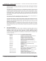
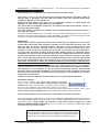
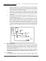
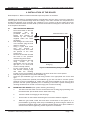
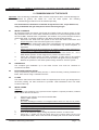
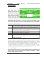
3.1 DIMENSIONS AND MINIMUM
CLEARANCES
The boiler must be installed in minimum
clearances shown to allow subsequent
servicing, and safe operation. However, larger
clearances may be required during installation.
3.2 SERVICE CONNECTIONS
Without Optional Pre-Installation Jig:
Gas, water, air and flue pipe, condensation,
and electrical connections are as shown. Gas :
15mm compression. Flow/Return 0.75BSPM
compression. DHW/CWS 0.5BSPM
compression.
With Optional Pre-Installation Jig:
Gas, water, air and flue pipe, condensation,
and electrical connections are as shown. Gas :
15mm compression. Flow/Return 22mm
compression. DHW/CWS 15mm
compression.
An optional stand-off frame is also available
which mounts behind the boiler to leave a
50mm deep space behind the boiler. This is
to permit pipe routing behind the boiler if
required. See Section 2.5 - Optional
Accessories.
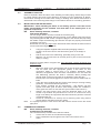
3.3 POSITION
The C36 Combi and C36P Combi are not
suitable for external installation. The boiler
may be installed in any room or internal
space, although particular attention is drawn
to the requirements of the current IEE Wiring
Regulations and, in Scotland, the electrical
provisions of the Building Regulations
WD388/0/2004 Chapter 3 - Boiler Location The Keston C36 Combi & C36P Combi Boilers
Installation & Servicing Instructions Page : 10
$OOGLPHQVLRQVLQPP
:KHQVHUYLFLQJDSSOLDQFH
)LJXUH
0LQLPXP&OHDUDQFHV
:KHQDSSOLDQFHLVRSHUDWLQJ
$OOGLPHQVLRQVLQPP
3
0
0
Figure 3.1.2
Dimensions
)OXH
$LU,QWDNH

applicable in Scotland, with respect to the installation of the boiler in a room or internal
space containing a bath or shower.
Where a room-sealed appliance is installed in a room containing a bath or shower, any
electrical switch or appliance control, utilising mains electricity, should be so situated that
it cannot be touched by a person using the bath or shower. The C36 Combi and C36P
Combi are classified as IP20 (IPX0) and are therefore suitable for installation in Zone 3
areas, unless subject to hose down.
Compartment installation is permitted - such compartments must be constructed in
accordance with BS 6798.
The wall on which the boiler is mounted must be of suitable load bearing capacity and
must be non-combustible.
The Keston C36 Combi can be located virtually anywhere desired provided that all
regulations are complied with. Because of the boiler's compact size and venting flexibility,
the installation is not limited to a boiler room setting. Before locating the boiler near a living
space consider whether the sounds generated by the boiler will be objectionable. The
boiler may be located within a cupboard enclosure to reduce noise levels if located within
a living space. LPG boilers must not be installed in a cellar.
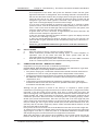
3.4 ELECTRICAL
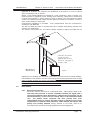
3.4.1 Electrical Connections
The boiler must be connected to a permanent 230V ~ 50Hz supply, fused at 3A.
The boiler has provision to receive a 230VAC switched live signal from a
room thermostat/time clock. Alternatively, a Keston Room Controller can be
connected directly, via two core low voltage cable, to the terminals marked
“OT”. The Keston Room Controller will then provide fully room
compensated control to ensure the boiler output is matched to the rooms
requirements at optimum boiler efficiency. DHW demand will always take
priority over heating demand. Wiring external to the boiler must be in
accordance with current I.E.E wiring regulations and local regulations.
WD388/0/2004 Chapter 3 - Boiler Location The Keston C36 & C36P Combi Boilers
Installation & Servicing Instructions Page : 11
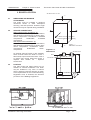
&KLPQH\VQRWXVHGIRU
YHQWLQJDQ\RWKHU
DSSOLDQFHPD\EHXVHG
)LJXUH
6HFXUHDLUIOXHSLSHVDW
FKLPQH\RXWOHW
[NB: Refer to
Section 3.8.3]

The method of connection to the mains electricity supply must facilitate complete
electrical isolation of the boiler, preferably by the use of a fused, unswitched three
pin plug and a shuttered socket-outlet, both complying with the requirements of
BS 1363. There must be only one common method of isolation for the boiler and
its control system.
The appliance must be connected to the 3A supply via a fused double-pole switch
having at least 3 mm (1/8 inch) contact separation in both poles, serving only the
boiler and the system controls.
The connection point to the mains supply should be readily accessible and
adjacent to the boiler, except for rooms containing a bath or a shower. Refer to
section 3.3 Position.
3.4.2 External Wiring & Controls
1. The boiler is designed so that all control wiring is external to the boiler.
2. Heating control signal inputs must the 230VAC "switched live" type unless
using a Keston Room Controller (see below)
3.4.2.1 Enhanced Control Options
Room Compensation (Opentherm)
A Keston Room Controller may be used to provide room compensated
control to ensure the boiler output is matched to the rooms requirements
at optimum boiler efficiency
Weather Compensation
A Keston outside temperature sensor may be connected as an option.
The boiler will automatically detect this connection and will operate on a
"weather compensation" basis when receiving a heating demand signal
from the SL terminal or from a Keston Room Controller. Screened cable
(80% density) must be used to connect the outside temperature sensor.
3.5 BOILER SIZE SELECTION
The C36 Combi will automatically adjust heat output and pump speed to match the
system requirements at any given time. Efficiency and combustion levels are maintained
at optimum levels throughout the possible output range. The C36 Combi is therefore
suitable for all systems with a total heat load within the maximum range of the boiler.
3.6 GAS SUPPLY
A gas meter should be connected to the service pipe by the local gas region or their
contractor. An existing meter should be checked preferably by the gas region to ensure
that the meter is adequate to deal with the rate of gas supply required. Installation pipes
should be fitted in accordance with BS 6891.
Minimum/Maximum Gas Pressure:
Natural gas pressure before the gas valve must be maintained at between 18 mbar (7.2 in
WG) and 22 mbar (8.8 in) while the boiler is running
.
LPG pressure must be maintained between 31.5 mbar (12.4 in w.g) and 37.6 mbar (14.8
in w.g) while the boiler is running.
WD388/0/2004 Chapter 3 - Boiler Location The Keston C36 Combi & C36P Combi Boilers
Installation & Servicing Instructions Page : 12
Live
Neutral
Earth
Mains Supply
230V
Fused @ 3A
Room Thermostat
T6360B1028
1
2
3
KESTON
C36 Combi
L
N
E
SL
3.4.2 Wiring Example
OTC
OTC
To Keston
Ext. Sensor
[Optional]
OT
OT
To Keston
Room Controller
[Optional - instead of room thermostat]

Gas pressures above or below these levels will lead to problems associated with the gas
valve's internal pressure regulator.
Supply pipes to the boiler must not be sized less than the boiler inlet connection
(15 mm). Due consideration must be given to the supply pressure to other gas
appliances in the premises. Reduction in dynamic gas supply pressure will result in
intermittent ignition failures. Ensure gas supply pipe work is adequately sized for
the length of run from the meter to the boiler at a supply rate of 40kW (i.e. a natural
gas supply should be considered to be a minimum of 22mm diameter, reducing to 15mm
at the boiler. If gas runs greater than 12m, including the allowance for bends, are involved
the pipe size should be increased further).
3.7 CH & DHW WATER SYSTEMS
All piping must be installed in accordance with all applicable local and Water Supply
Bylaws for forced hot water heating systems.
Consideration must be given to pipe capabilities and pressure drop through the piping
when selecting pipe sizes. The primary pipe connections to the boiler must be sized
according to the system load, not dictated by the boiler connection sizes.
Water treatment must
be carried out to BS 7593 : Treatment of Water in Hot Water
Central Heating Systems.
In IE the requirements given in the current edition of IS813 and the current Building
Regulations must be followed.
a The Keston C36 Combi is designed for installation on sealed water systems only.
With fully pumped water circulation. The pump, an 8l expansion vessel and
associated safety devices are fitted within the boiler.
b Any system must
be thoroughly flushed clean of grease, dirt and debris, prior to
connection with the boiler. A trap may be installed in the flow line to collect any
solder, or other debris, from the installation.
c All water systems must be constructed to comply with requirements of the Local
Water Authority.
d Always use a system complying with the requirements of BS 5449 and BS 6798.
e System design must ensure an open circuit is always available to ensure
circulation when the pump overrun function is operating after boiler shutdown.
f Isolation valves must be fitted on the cold mains supply, the heating flow and the
heating return to enable isolation when maintaining the boiler. Such isolation
valves are included in the optional pre-installation jig (C.10C.0.11.00.0)
g Copper tubing to BS 2871 Part 1 or barrier plastic pipe suitable to 110
o
C, such as
Unipipe, is recommended.
h Jointing should be either with capillary, threaded or compression fittings. Pipes
should have a gradient to ensure air is passed easily to vent points and water
flows readily to drain points.
i Draining taps must be located in accessible positions which permit the draining of
the boiler. Draining taps should be at least 22 mm in nominal size and be in
accordance with BS 2879. A drain tap is incorporated into the optional
pre-installation jig (C.10C.0.11.00.0)
AIR VENT POINTS
j These must be fitted at all high points where air will naturally collect and must be
sited to allow complete draining of the system.
Table 3.7 Additional Expansion Vessel Selection
13.6
125 litres
10.9
100 litres
8.2
75 litres
5.4
50 litres
2.7
25 litres
Vessel
Volume
Total Water Content of system in
excess of 125 litres
1.0 bar
Vessel charge & initial system
pressure.
3.0 bar
Safety Valve Setting
WD388/0/2004 Chapter 3 - Boiler Location The Keston C36 & C36P Combi Boilers
Installation & Servicing Instructions Page : 13

k. The boiler is supplied with an integral expansion vessel of 8l capacity. This is
suitable for systems of up to 125 Litres system volume. Table 3.7 Expansion
Vessel Selection provides guidance for the correct additional expansion vessel
size to use for systems with a water content larger than 125 Litres. Any additional
vessel must be fitted on the boiler primary return.
l A filling point must be fitted, in accordance with local water authority
requirements. An approved filling loop is supplied loose with the boiler installation
jig. There must be no permanent connection to the mains water supply. The filling
loop must therefore be left isolated at both ends and disconnected after the
system is filled.
m The installation must be designed to work with flow temperatures of up to 110
o
C.
All components of the system must be suitable for a working pressure of 3 bar
and a temperature of 110
o
C. Care should be taken in making all connections that
the risk of leakage is minimised.
n The pipe from the safety discharge valve must not discharge above an entrance,
window or any type of public access area. The boiler safety discharge valve pipe
must be extended using not less than 15mm pipe to discharge, in a visible
position, outside the building, facing downwards, preferably over a drain. The
pipe must have a continuous fall and be routed to a position so that any discharge
of water, possibly boiling, or steam cannot create any danger to persons, damage
to property or external electrical components or wiring. To ease future servicing it
is advisable to use a compression type fitting to extend the safety discharge valve
pipe.
3.7.1 Boiler By-pass Piping
Boiler water flows are critical to the operation of the boiler. If flow cannot be maintained
through the system piping to meet the minimums required by the boiler, insufficient water
flows through the boiler will cause the boiler to "kettle" or even produce steam which can
damage the heat exchanger and will invalidate the heat exchanger warranty. In addition,
an open circuit is required after boiler shutdown to permit circulation during the boilers 2
minute pump overrun sequence.
It is advisable to incorporate a boiler by-pass in the system, especially if thermostatic
radiator valves are used. The flow/return differential should be 10
o
C to 20
o
C. To comply
with the Building Regulations Part L1 the bypass must of the automatic type.
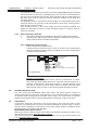
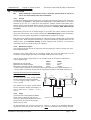
3.7.2 Air Elimination
In the initial charge of water to the boiler system and in all subsequent additions of water
to the system some air will be dissolved in the water. As the water is heated the air is
WD388/0/2004 Chapter 3 - Boiler Location The Keston C36 Combi & C36P Combi Boilers
Installation & Servicing Instructions Page : 14
COMBI
KESTON
Expansion
Isolating Valve
HEATING CIRCUIT
FLOW
RETURN
(disconnected
after filling)
Flex Hose
Isolating & Dbl Chekc Valve
By-pass
(if required)
Drain
Cock
(if required)
DOMESTIC WATER
DOMESTIC HOT WATER
COLD WATER SUPPLY
Vessel
Figure 3.7 : CH & DHW Sealed Systems Diagram

driven out of the solution and will
collect in high spots in the
system. These air bubbles can
interfere with pumping and
heat transfer and must be
eliminated.
Installation of air bleed valves at
the high spot(s) in the system
will allow for air elimination when
filling the system and will allow
re-venting in a day or so after all
air has been driven out of
solution.
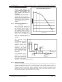
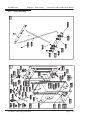
3.7.3 System Pump Selection (if
required)
The C36 Combi features an
integral circulating pump which
has sufficient excess head to
drive most domestic systems.
The available head is shown in
the graph below. If the system
index circuit resistance is in
excess of the available head
from the integral pump an
additional system pump will be
required.
The schematic below
illustrates a
recommended approach
to using an additional
system pump. The
additional system pump
should be sized to
overcome the index
circuit resistance only as
the boilers integral pump
will overcome boiler
resistance.
If an additional pump is
required the selected
pump must comply with
BS 1394. Provision must
be made in the system
design for control of the additional pump.
3.7.4 Filling The System
The boiler is supplied with an approved filling loop device. This filling device is designed to
enable initial fill and topping up of system pressure. The system should be set to a
pressure of between 1.0 and 1.5 bar. To display the system water pressure press the
“Installer” button, on the boiler fascia, repeatedly until the number 5 appears on the
display. After a few seconds the display will change to show the water pressure, in bars.
Using the filling loop set the pressure to 1.0 to 1.5 bar,
WD388/0/2004 Chapter 3 - Boiler Location The Keston C36 & C36P Combi Boilers
Installation & Servicing Instructions Page : 15
Additional System
Pump
(if required)
COLD WATER SUPPLY
DOMESTIC HOT WATER
DOMESTIC WATER
(if required)
COMBI
HEATING CIRCUIT
KESTON
Expansion
Vessel
Drain
Cock
RETURN
FLOW
Permanently
Open 28mm
By-pass
C36 Combi Available pum p head
0
1
2
3
4
5
6
7
0 5 1 0 1 5 20 25 30 35 40
F l o w R a t e ( l p m )
Page is loading ...
Page is loading ...
Page is loading ...
Page is loading ...
Page is loading ...
Page is loading ...
Page is loading ...
Page is loading ...
Page is loading ...
Page is loading ...
Page is loading ...
Page is loading ...
Page is loading ...
Page is loading ...
Page is loading ...
Page is loading ...
Page is loading ...
Page is loading ...
Page is loading ...
Page is loading ...
Page is loading ...
Page is loading ...
Page is loading ...
Page is loading ...
Page is loading ...
Page is loading ...
Page is loading ...
Page is loading ...
Page is loading ...
Page is loading ...
Page is loading ...
Page is loading ...
Page is loading ...
Page is loading ...
Page is loading ...
Page is loading ...
Page is loading ...
-
 1
1
-
 2
2
-
 3
3
-
 4
4
-
 5
5
-
 6
6
-
 7
7
-
 8
8
-
 9
9
-
 10
10
-
 11
11
-
 12
12
-
 13
13
-
 14
14
-
 15
15
-
 16
16
-
 17
17
-
 18
18
-
 19
19
-
 20
20
-
 21
21
-
 22
22
-
 23
23
-
 24
24
-
 25
25
-
 26
26
-
 27
27
-
 28
28
-
 29
29
-
 30
30
-
 31
31
-
 32
32
-
 33
33
-
 34
34
-
 35
35
-
 36
36
-
 37
37
-
 38
38
-
 39
39
-
 40
40
-
 41
41
-
 42
42
-
 43
43
-
 44
44
-
 45
45
-
 46
46
-
 47
47
-
 48
48
-
 49
49
-
 50
50
-
 51
51
-
 52
52
-
 53
53
-
 54
54
-
 55
55
-
 56
56
-
 57
57


Keston C36 Installation guide
- Category
- Water heaters & boilers
- Type
- Installation guide
Ask a question and I''ll find the answer in the document
Finding information in a document is now easier with AI
Related papers
-
Keston K260 Installation guide
-
-
-
-
-
-
-
-
-
Other documents
-
Ideal Boilers Vogue Max Combi IE Installation & Servicing User manual
-
Baxi Combi Instant 80 HE Quick start guide
-
Radiant RK 25 OV User manual
-
 Trianco TRISTAR OPTIMA JUNIOR K CB Installation Instructions Manual
-
VOKERA Linea Plus Datasheet
-
Noritz America CB199-DV-LP User manual
-
Chaffoteaux & Maury Britony Combi SE Maintenance And Service Manual
-
Wolf CGB-75 Installation And Operating Instructions Manual
-
-
MONDOLUX MD68 User manual
