Page is loading ...

© 2013 UTC Fire & Security. All rights reserved. 1 / 4 P/N 3101195 • REV 02 • REB 28JAN13
E-NAC Analog NAC Module Installation Sheet
Operation
The module is an analog addressable device used to connect
a supervised output circuit to a signal riser. The output wiring is
monitored for open and short circuits. A short circuit causes the
module to inhibit the activation of the audible/visual signal
circuit so the riser is not connected to the wiring fault. Upon
command from the control panel, the module connects the
output circuit to the riser input. The output circuit energizes a
riser to operate polarized audible and visual signals. The
module can be used for connection of a Class A or Class B
(with EOL) output notification appliance circuit (NAC).
The device address is set using the two rotary switches located
on the front of the module. One device address is required.
The module is configured to operate as a Genesis
Audible/Visual/Silence device type from the factory. The
module can also be configured for other device types through
front panel programming or the configuration utility. Refer to
the applicable control panel technical reference manual for a
list of available device types.
Genesis Audible/Visual/Silence: Used with Genesis and
Enhanced Integrity horns and strobes. Genesis and Enhanced
Integrity appliances maintain synchronization per UL 1971. For
Genesis devices, this configuration allows connected horns to
be silenced while strobes on the same two-wire circuit continue
to flash until the panel is reset.
Note: You may use nonsynchronous fire alarm signals with or
instead of compatible synchronized fire alarm signals, but the
operation of these devices will not comply with UL 1971.
LED operation
The module provides a bicolor LED that shows its status.
Normal: Green LED flashes
Active: Red LED flashes
Installation
WARNINGS
• This module will not operate without electrical power. As
fires frequently cause power interruption, you should
discuss further safeguards with your local fire protection
specialist.
• This module does not support conventional smoke
detectors.
Note: The module is shipped from the factory as an assembled
unit; it contains no user-serviceable parts and should not be
disassembled.
To install the module:
1. Verify that all field wiring is free of opens, shorts, and
ground faults.
2. Make all wiring connections as shown in “Wiring.”
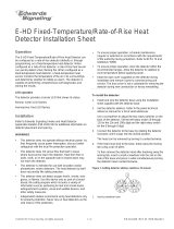
3. Set the module address as follows:
Use a screwdriver to adjust the two rotary switches on the
front of the module. Set the TENS rotary switch (0 through
12) for the 10s and 100s digit and the ONES rotary switch
for the 0 through 9 digit. For example: device address 21,
set TENS rotary switch to 2 and set the ONES rotary
switch to 1.
Refer to “Specifications” for available address numbers.
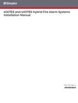
4. Mount the module on the electrical box using screws
provided with the electrical box.
5. Mount the wall plate on the module using #4-24 x 1/2 in.
(13 mm) self-tapping screws.
Figure 1: Module address
Insert
screwdriver
here

2 / 4 P/N 3101195 • REV 02 • REB 28JAN13
Figure 2: Module installation
Screw
4-24
screws
Module
Wall plate
Compatible
electrical box
Specifications
Communication line voltage
Maximum 20.6 V peak-to-peak
Current
Standby
Activated
350 μA
200 μA
Ground fault impedance
10 kΩ
Operating environment
Temperature
Humidity
32 to 120° F (0 to 49° C)
0 to 93% RH, noncondensing at
90° F (32° C)
Output ratings
Circuit current
EOL resistor value
24 VDC at 2 A max.
47 kΩ, (P/N: EOL-47)
Storage temperature range
–4 to 140° F (–20 to 60° C)
Compatible electrical boxes
North American 4 inch square x
2-1/2 in. (64 mm) deep 2 gang box
Standard 4 in. square box 1-1/2 in.
(38 mm) deep
Wire size
12, 14, 16, or 18 AWG wire (2.5, 1.5,
1.0, or 0.75 mm
2
) (Sizes 16 and 18
AWG are preferred)
Device address
01 to 64 (64 point control panel)
01 to 127 (127 point control panel)
Wiring
Wire in accordance with NFPA 72 and CAN/ULC-S524. Be
sure to observe the polarity of the wires as shown in Figure 3.
Transient protection caution
The module requires transient protection for installations that
connect electromechanical bells or horns to output circuits. The
module's circuitry requires a bipolar transient protector
(P/N 235196P) for protection against transient spikes caused
by the inductive load of bells or horns.
Connect the bipolar transient protector assembly across the
terminals of the bell or horn electrically closest to the module.
The bipolar transient protector is not polarity-sensitive.
Locate bells and horns at least 6 ft. (1.83 m) from the module.

P/N 3101195 • REV 02 • REB 28JAN13 3 / 4
Figure 3: Module wiring
From
listed
power
supply
[2] [3] [5]
[4]
24 VDC (+)
24 VDC
Circuit wired
same as
diagram above
Style Z (Class A)
[1] [2] [5] [6]
Style Z (Class A)
[1] [2] [5] [6]
Style Y (Class B)
[1] [2] [5] [6]
Style Y (Class B)
[1] [2] [5] [6]
[8]
Typical bell circuit
Typical horn or
strobe circuit [7]
47 k EOLR
Used for
Class B only
Ω
47 k EOLR
Used for
Class B only
Ω
TB2 TB1
+ +
− −
+ +
− −
+ +
-
-
RETURN
NAC PWR. IN
NAC
SLC
(+)
(+)
From
previous
device
To next
device
SLC out (+)
SLC out
SLC in
SLC in (+)
( )
( )
( )
( )
( )
( )
( )
Notes
[1] Maximum 25 Ω resistance per wire. Maximum circuit capacitance of 0.1 μF
[2] Maximum 12 AWG (2.5 mm
2
) wire; minimum 18 AWG (0.75 mm
2
) wire
[3] Refer to the control panel technical reference manual for wiring specifications
[4] If the NAC power riser is used for more than one notification zone, install in accordance with the survivability from attack by fire requirements
in NFPA 72
[5] Supervised
[6] Polarity shown in alarm condition. Polarity reverses on supervisory condition
[7] Typical synchronized temporal horn/strobe circuit when configured as Class A/B auto sync signal output module through programming
[8] Transient protection (see “Transient protection caution”)

4 / 4 P/N 3101195 • REV 02 • REB 28JAN13
/