Page is loading ...

Stinger Manual Issue 3 Jan 2011 Page 1 of 4
mobile alarm system
Introducing the new Sargent STINGER 310 series modular alarm system.
Based on new technology and a two year design process, the Stinger 310 incorporates ideas and
feedback from users and experts throughout the caravan and security industries.
Designed to be modular, the system can be expanded by a forthcoming range of wired and wireless
accessories.
To ensure your STINGER 310 system is operated correctly, please read all sections of these
instructions before attempting to use the alarm. If you are unsure of any content, please contact your
supplier in the first instance or the manufacturer direct.
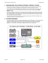
Each STINGER 310 is supplied with two key fob style radio controllers, which are used to
operate the alarm system. Each key fob has four buttons which can be used as follows;
LED Torch button
Press and hold the button to use the torch for night time convenience
Arm / Disarm button
Press and release the button to arm the alarm (one beep)
Press and release the button to disarm the alarm (two short beeps)
To arm the alarm without the PIR movement sensor (if you leave pets inside etc) press and
hold the arm button and release after you hear one beep followed by two beeps
Awning Light button
Press and release the button to turn the awning light on or off
(note: awning light control is an optional feature not present in all caravan models)
Programming Mode button
Press and hold the button for 10 seconds to access the 3 programming modes, which are
indicated by series of long beeps, as follows:
Operation-using the key fob
Press the program mode button again to exit programming mode, which is indicated by one extra long
beep.
P
One long beep -Tilt sensor adjustment
Press the arm/disarm button to select the required setting. 1 beep = low sensitivity for windy conditions. 2 beeps = standard
sensitivity (default). 3 beeps = High sensitivity. Press the program mode button to move to the next setting.
Two long beeps -Beeper volume adjustment
Press the arm/disarm button to cycle through the 7 available volume levels. When you are happy with the selected volume,
press the program mode button to move to the next setting.
Three long beeps -PIR movement sensor adjustment
Press the arm/disarm button to select the required setting / pulse count. 1 beep = high sensitivity for hot environments.
2 beeps = standard sensitivity (default). 3 beeps = low sensitivity for hostile / cold environments.

Stinger Manual Issue 3 Jan 2011 Page 2 of 4
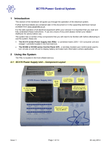
The STINGER 310 comes complete with a 120° Passive Infra Red (PIR) internal movement sensor
that detects body movement within the vehicle. With the system disarmed a green LED within the PIR
will indicate movement detection.
Operation-the PIR internal movement sensor
If you are leaving pets within the vehicle the system should be armed without
the PIR sensor active (see key fob arm/disarm section) to prevent your pet
from triggering the alarm.
Please be aware that extremes of temperature can affect the operation of the
PIR. With temperatures above 30 deg C the PIR’s ability to detect a human
body is reduced, and therefore the sensitivity can be adjusted to improve
detection. With temperatures below zero the PIR’s sensitivity will increase,
and therefore the sensitivity can be reduced to eliminate false triggering.
Please ensure roof light blinds are closed if sunlight could shine directly onto
the PIR. If heating vents are located near the PIR please ensure these are
closed to prevent cold draughts affecting the PIR.
The STINGER 310 incorporates a new electronic tilt and motion sensor with automatic calibration
and easy sensitivity adjustment from the key fob. This feature provides excellent tilt detection with no
moving parts.
Operation-the tilt sensor
The tilt sensor works automatically and does not need adjustment for normal
use even if you park on a steep incline. The sensitivity of the sensor can be
adjusted as described in the key fob programming section.
Operation -awning light
When the STINGER 310 alarm system is armed or disarmed the awning light will be activated for a
period of one minute to provide illumination whilst entering or exiting the caravan. The awning light
can be turned off during this period by pressing the awning light button on the key fob if required.
(note: awning light control is an optional feature not present in all caravan models)
The awning light can be turned on or off at any time by pressing and releasing the awning light button.
Operation -marker / tail lights
When the STINGER 310 alarm system is armed or disarmed the marker / tail lights will flash to
indicate the armed or disarmed state of the alarm.
One flash indicates armed and two flashes indicates disarmed. These flashes match the arm / disarm
beeps described earlier.
When the alarm is triggered the marker / tail lights will flash for 2 minutes.
(note: marker / tail light control is an optional feature not present in all caravan models, and will only
operate when a leisure battery is fitted)

Stinger Manual Issue 3 Jan 2011 Page 3 of 4
The STINGER 310 contains a dual sounder unit that provides the loud alarm siren and the volume
adjustable beeper sound.
When the alarm is triggered the siren will sound for 2 minutes. Following the 2-minute period the
alarm will then deactivate for 15 seconds and then rearm.
The alarm siren can be turned off at any point by pressing the key fob arm/disarm button.
When the alarm is disarmed the beeper will sound two beeps to confirm the disarm. If the alarm has
been triggered during the armed period the beeper will sound three beeps if the PIR triggered the
alarm, four beeps if the tilt sensor caused the alarm and five beeps if the PIR security loop or accessory
sensor caused the alarm. If you hear multiple pips (short beeps) when you disarm the alarm, this
indicated that the internal backup battery is low and therefore should be charged.
The beeper volume can be adjusted using the key fob programming feature described earlier.
Alarm siren
The STINGER 310 key fob controllers use two lithium button cells (CR 2032) in each key fob. Please
note that excessive use of the LED torch will reduce the life of the batteries considerably.
To replace the batteries, firstly remove the four cross head screws from the underside of the fob, then
pull apart the two halves of the fob. Remove the used batteries from the lower half of the case, then
insert the new batteries in the same manner, noting that the battery positive (+) faces away from the
green circuit board. Now reassemble the fob casing and refit the screws, taking care not to over
tighten.
Battery -key fob
The STINGER 310 system unit uses a special 4.8 volt Nickel Metal Hydride battery pack that supplies
backup battery power to the system should the supply from the leisure battery fail or be disconnected.
It is recommended that the alarm system is permanently connected to a 12 volt supply. When fully
charged the battery will provide approximately 6 months stand-alone operation, depending on
temperature conditions. It is recommended that this battery pack is replaced every 3 years.
If the battery becomes discharged this will be indicated by a flashing red LED in the PIR and a periodic
beep from the beeper. (note: see section below regarding beeps on disarming)
Before placing your caravan in storage please ensure the caravan has had a fully charged leisure
battery fitted or the mains charger switched on for at least 14 days prior to storage to ensure the the
internal backup battery is fully charged. It is recommended that a leisure battery remains connected to
the caravan during storage.
Always dispose of old batteries in accordance with local regulations.
Battery -system base unit
The STINGER 310 system is installed by many caravan manufacturers as standard equipment and
can also be installed by specialist dealers / installers. If you require installation instructions please
contact our service desk (see section below).
If you are adding other electrical equipment to your caravan, such as motor movers, vehicle trackers or
other radio controlled equipment, please ensure that the equipment is positioned at least 500mm away
from the Stinger 310 base unit and PIR.
Installation

Stinger Manual Issue 3 Jan 2011 Page 4 of 4
System base unit
Supply voltage 6 to 15v DC
Supply current 500mA max 5mA typical
Operating temperature -20 to +40 deg Celsius
Battery capacity 9Ah at 4.8v
Siren output 110dB +/-10% @ 1M
Comprehensive interface connector (details
on request)
System specification
PIR movement sensor
Range 120 deg x 6M
Key fob controller
Range 6M typical
Battery 2x CR2032 lithium button cell
Typical battery life 1 year
For future reference it may be useful to note your alarm system serial number below, which can be
found on the sticker attached to the alarm system base unit.
Serial number: ………………………………………………………….…….
For your reference
The STINGER 310 system is supplied with two key fob controllers as standard, but can accommodate
up to four controllers per system. Extra fobs can be purchased from your supplier of direct from the
manufacturer, and can be added to the system by following a simple procedure.
For accessories, interface harnesses, installation documentation, spare parts, local supplier contact
details or other service information please contact: Sargent Electrical Services Ltd. service desk on
01482 678981 during normal office hours.
Further technical information is available at www.sargentltd.co.uk
Spare parts & service
/