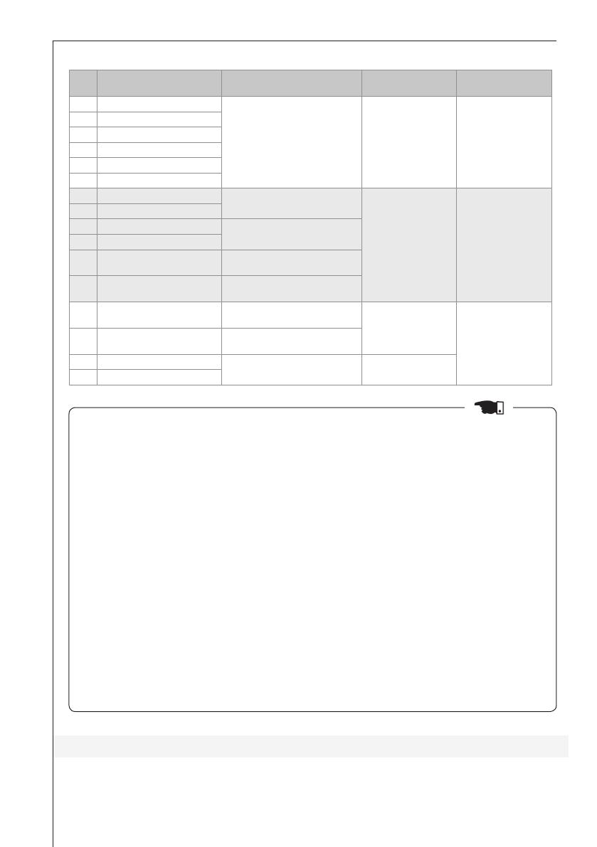
WEG CFW-08 User manual

Type
User manual

WEG CFW-08 is a frequency inverter with a Type 4X protection degree, ensuring protection against dust, dirt, and directed water jets. It's suitable for indoor and outdoor use in harsh environments like washdowns, food and beverage processing, and wastewater treatment plants. The CFW-08 supports various motor control functions, including speed control, torque control, and positioning control. It also offers advanced features such as sensorless vector control, field-oriented control, and energy-saving modes.

WEG CFW-08 is a frequency inverter with a Type 4X protection degree, ensuring protection against dust, dirt, and directed water jets. It's suitable for indoor and outdoor use in harsh environments like washdowns, food and beverage processing, and wastewater treatment plants. The CFW-08 supports various motor control functions, including speed control, torque control, and positioning control. It also offers advanced features such as sensorless vector control, field-oriented control, and energy-saving modes.

Motors | Energy | Automation | Coatings

CFW-08 Wash

Language: English


1. Introduction .................................................................................................... 4
2. Installation and Connection .............................................................................. 4
2.1 Environment .............................................................................................. 4
2.2 Dimensions ................................................................................................ 4
2.3 Location of the Power, Ground and Control Connections ............................... 5
2.4 Electrical Installation ................................................................................... 7
2.4.1 Power/Ground Connection Wiring and Circuit Breakers ....................... 7
2.4.2 Signal and Control Connections ......................................................... 8
2.5 European Electromagnetic Compatibility Directive - Proposed Filters ............... 9
2.5.1 Inverters and Filters ............................................................................ 9
2.6 Closing the Inverter ................................................................................... 10
3. Human Machine Interface (HMI) ...................................................................... 11
4. Optional Devices and Accessories ................................................................... 12
5. Models .......................................................................................................... 13
5.1 200-240 V Line ........................................................................................ 13
5.2 380-480 V Line ........................................................................................ 14
5.3 500-600 V Line ........................................................................................ 15


- The information contained here applies to inverters having the N4 abbreviation in
the intelligent code, for instance: CFW080073T2024PON4A1Z. In order to get more
information on the intelligent code, refer to the user manual section 2.4.
- Use this guide together with the CFW-08 user manual.

The frequency inverter CFW-08 Wash is an inverter dedicated to applications that require
a higher protection degree. The Type 4X protection degree assures protection against dust,
dirt and directed water jets.


The recommended environments for the CFW-08 Wash use are:
- Type 4X indoor;
- IP66;
- Nema 12 indoor.
Other considerations and specifications about the environment are identical to those for
the CFW-08 IP20 (refer to the chapter 3 of the CFW-08 user manual).

The figures 2.1 a) and 2.1 b) present the dimensions of the CFW-08 Wash.
70,5 2,774
38 1,49638 1,496
216 8,504
165 6,496
265 10,433
237,9 9,367
ENTRADA DO
FLUXO DE AR
7,5 0,295
7,5 0,295
5,7 0,223
250 9,843
A
B
5,7 0,223
PARAFUSO M5
R
2,8 0,111
7,5 0,295
10,8 0,423
DETALHE A
ESCALA 4 : 1
PARAFUSO M5
5,7 0,223
DETALHE B
ESCALA 4 : 1
SAÈDA DO
FLUXO DE AR
View A
Scale 4:1
View B
Scale 4:1
5.7 [0.223]
5.7 [0.223]
5.7 [0.223]
38 [1.496]
165 [6.496]
38 [1.496]
Air Flow
7.5 [0.295]
7.5 [0.295]
250 [9.843]
237.9 [9.367]
265 [10.433]
70.5 [2.774]
R2.8 [0.111]
M5 SCREW
M5 SCREW
7.5 [0.295]
216 [8.504]
10.8 [0.423]
28.3 [1.11]
Figure 2.1 a) - CFW-08 Wash dimensions in mm [in] – Models: 7.3 – 10 – 16 A/200-240 V and
2.7 – 4.3 – 6.5 – 10 A/380-480 V
45 1,772
128 5,039
69,5 2,735
216 8,504
215 8,465
340 13,386
313,8 12,356
ENTRADA DO
FLUXO DE AR
200 7,874
7,5 0,295
7,5 0,295
325 12,795
5,7 0,223
A
B
5,7 0,223
R
2,8 0,111
PARAFUSO M5
7,5 0,295
10,7 0,423
DETALHE A
ESCALA 4 : 1
PARAFUSO M5
7,5 0,295
7,5 0,295
DETALHE B
ESCALA 4 : 1
SAÈDA DO
FLUXO DE AR
View A
Scale 4:1
View B
Scale 4:1
200 [7.874]
5.7 [0.223]
5.7 [0.223]
45 [1.772]
215 [8.465]
128 [5.039]
Air Flow
7.5 [0.295]
7.5 [0.295]
7.5 [0.295]
7.5 [0.295]
325 [12.795]
313.8 [12.356]
340 [13.386]
69.5 [2.735]
10.7 [0,423]
R2.8 [0.111]
M5 SCREW
M5 SCREW
7.5 [0,295]
216 [8.504]
28.3 [1.11]
Figure 2.1 b) - CFW-08 Wash dimensions in mm [in] – Models: 22 28 33 A/200-240 V, 13 –
16 – 24 – 30 A/380-480 V and 1.7 – 3.0 – 4.3 – 7.0 – 10 – 12 A/500-600 V

The positioning, fixing and mounting recommendations described in the CFW-08 user
manual must be considered (refer to the chapter 3).

In order to get access to the power, control and ground terminals, it is necessary to remove
the inverter front cover, as indicated in the figure 2.2. Disconnect cable XC6 at the front cover.
Figure 2.2 - Procedure for the CFW-08 Wash front cover removal
The figure 2.3 presents the location of the power and control terminal strips, as well as
the ground connection point.
Control Terminal Strip
Power Terminal Block
b) Models: 22 28 33 A/200-240 V, 13 16 24 30 A
/ 380-480 V and 1.7 – 3 4.3 – 7 10 12 A/500-600 V
Ground
Ground
Entry for the
Supply Cables
Entry for the
Dynamic
Braking
Cables

Entry for
the Motor
Cables
Entry for
the Control
Cables
a) Models: 7.3 – 10 – 16 A/200-240 V
and 2.7 – 4.3 – 6.5 – 10 A/380-480 V
Control
Terminal
Strip
Power
Terminal Block
Entry for the
Supply Cables
Entry for the
Motor Cables
Entry for
the Control
Cables
Entry for the
Dynamic
Braking
Cables

Ground
Ground
(1)- When using the dynamic braking with the 7.3 A, 10 A and 16 A/200 240 V and 2.7 A, 4.3 A, 6.5 A
and 10 A/380 480 V models, it is necessary to remove the opening knockout and use appropriate
Type 4X cable and cable gland.
- Entry diameter: 16.1 mm (0.63 in).
- Cable gland: M16 x 1.5 or PG9.
(2)- In order to comply with UL standard, cables type S or SJ suitable for wet locations and marked with
“W” should be used to assure Type 4X protection degree.
Figure 2.3 a) and b) - Location of the power, ground and control connections

Before performing this operation, remove the power from the inverter and wait 10 minutes
for the complete discharge of the capacitors.


Refer to the chapter 3 in the CFW-08 user manual.

- The use of appropriate cables is essential to assure the Type 4X protection degree. The
use of multi core cables is recommended. For instance, a 4-core cable for the power
supply (R, S, T) and grounding, as well as another 4-core cable for the motor connection.
The figure 2.4 presents an example of a 4-core cable for the power section connections.
- In order to assure the Type 4X protection degree, it is necessary the use of cable glands
with a compatible degree of protection for the application at the power and control
connections.
Figure 2.4 - 4-core cable

Power supply line capacity: Type 4X devices are suitable for use on a circuit capable of
delivering not more than 30,000 Arms symmetrical amperes, 200-600 Volts maximum,
when protected by fuses rated 100 % of the drive input current. Voltage is the same as
the device maximum input voltage.

The signal (analog inputs and outputs) and control (digital inputs and relay outputs)
connections are made at the control board terminal strip XC1. The functions of the XC1
terminals are shown in the figure 2.5.
Connector
XC1
1 DI1
2 DI2
3 DI3
4 DI4
5 GND
6 AI1 or
DI5
or
PTC1
7 +10 V
8 AI2 or
DI6 or
PTC
9 AO
10 N.C
11 Commom
12 N.O.
13 GND
14 GND
15 GND
16 GND
Description
FactoryDefaultFunction
Digital Input 1
No Function or General Enable
Digital Input 2
FWD / REV
Digital Input 3
Reset
Digital Input 4
No Function or Start/Stop
0 V Reference
Analog Input 1 or Digital Input 5
or PTC1 Input
Frequency/Speed Reference
(remote mode)
Potentiometer Reference
Analog Input 2 or Digital Input
Digital 6 or PTC2 Input
Not Used
Analog Output
Output Frequency (Fs)
Relay Output 2 - N.C. Contact
Fs > Fx (P279 = 0)
Relay Outputs Common Points
Relay Output 1 - N.O. Contact
Not Fault (P277 = 7)
0 V Reference
0 V Reference
0 V Reference
0 V Reference
Specifications
4 isolates digital inputs
- Logic NPN
Minimum high level: 10 Vdc
Maximum high level: 30 Vdc
Maximum low level: 3 Vdc
- Logic PNP
Maximum low level: 10 Vdc
Minimum high level: 21.5 Vdc
Maximum high level: 30 Vdc
Input Current: -11 mA
Max. Input Current: -20 mA
Not connected to PE
(0 to10) Vdc (0 to 20) mA (4 to 20) mA and
(-10 to +10) Vdc*.
Impedance: 100 k (voltage input) and 500
(current input).
- Linearity error < 0,25 %
- Maximum voltage input: 30 Vdc
For further information refer to P235
detailed parameter description.
+10 Vdc ± 5 %, capacity: 2 mA
(0 to10) Vdc (0 to 20) mA (4 to 20) mA and
(-10 to +10) Vdc*.
Impedance: 100 k (voltage input) and 500
(current input).
- Linearity error < 0,25 %. Maximum voltage
input: 30 Vdc. For further information refer
to P239 detailed parameter description.
(0 to 10) Vdc, RL ≥ 10 kΩ
Resolution: 8 bits
Linearity Error < 0,25 %
Contact capacity:
0.5 A / 250 Vac
Not connected to PE
Not connected to PE
Not connected to PE
Not connected to PE
Relay 1
11
Relay 2
12 10
Factory default settings
RPM
-
+
CCW
CW
CCW
CW
≥10kΩ
≥10kΩ
Figure 2.5 - Description of the XC1 terminal strip for the control board A1 (CFW-08 Plus), control
board A2 (CFW-08 Plus with AI’s -10 V to +10 V), control board A3 (CFW-08 Plus with CANopen
protocol) and control board A4 (CFW-08 Plus with DeviceNet protocol)

1) Before making the connections, remove the power supply from the inverter and wait
10 minutes for the complete discharge of the capacitors.
2) In order to assure the Type 4X protection degree, it is necessary the use of cable glands
with a compatible degree of protection for the application at the power and control
connections.
3) If there is no electrical connections the rubber seals that come with the inverter must
be kept in place.
4) The maximum and minimum diameter of the power and control connection cables
must be according to the cable gland supplier specification, in order to assure the
specified protection degree.
5) The CFW-08 Wash has four (4) extra GND terminals compared to the CFW-08 IP20
in order to assist with the control connections.

In order to get more information on the control board installation and configuration, refer
to the CFW-08 user manual chapter 3.


The frequency inverters of the CFW-08 series were projected considering all the aspects
of safety and electromagnetic compatibility (EMC).

The emission levels for CFW-08 Wash models are different from those for the IP20 models.
The next table presents the filters and the categories for the CFW-08 Wash models according
to EN61800-3, edition 2, 2004-08.
Table 2.1 - Inverter model list, filters and EMC categories
Id InverterModel InputRFIFilter
Conducted
EmissionLevel
Radiated
EmissionLevel
1 CFW080073B2024...FAZ
(single-phase input)
Built-in Filter Category C3 Category C3
2 CFW080100B2024...FAZ
(single-phase input)
3 CFW080073B2024...
(single-phase input)
FS6007-25-08 or B84142-
A30-R122 (external filter)
Category C1 Category C2
4 CFW080073B2024...
(three-phase input)
FN3258-16-45 or B84143-
B25-R110 (external filter)
5 CFW080100B2024...
(single-phase input)
FS6007-36-08 or B84142-
A30-R122 (external filter)
6 CFW080100B2024...
(three-phase input)
FN3258-16-45 or B84143-
B25-R110 (external filter)
7 CFW080160T2024... FN3258-30-47 or B84143-
B36-R110 (external filter)
8 CFW080220T2024... B84143-B36-R110
(external filter)
9 CFW080280T2024... B84143-B50-R110
(external filter)
10 CFW080330T2024... B84143-B50-R110
(external filter)

Id InverterModel InputRFIFilter
Conducted
EmissionLevel
Radiated
EmissionLevel
11 CFW080027T3848...FAZ Built-in Filter Category C3 Category C3
12 CFW080043T3848...FAZ
13 CFW080065T3848...FAZ
14 CFW080100T3848...FAZ
15 CFW080130T3848...FAZ
16 CFW080160T3848...FAZ
17 CFW080027T3848... FN3258-7-45 or B84143-
B8-R110 (external filter)
Category C1 Category C2
18 CFW080043T3848...
19 CFW080065T3848... FN3258-16-45 or B84143-
B25-R110 (external filter)
20 CFW080100T3848...
21 CFW080130T3848... FN3258-16-45 or B84143-
G36-R110 (external filter)
22 CFW080160T3848... FN3258-30-47 or B84143-
G36-R110 (external filter)
23 CFW080240T3848... FN-3258-30-47 or B84143-
B50-R110 (external filter)
Category C1 Category C3
24 CFW080300T3848... FN-3258-55-52 or B84143-
B50-R110 (external filter)
25 CFW080240T3848...FAZ Built-in Filter Category C3
26 CFW080300T3848...FAZ

1) The inverters with conducted emission level Category C1 and the models 1 and 2, must
be mounted inside a metallic cabinet so that the radiated emissions be kept inside the
levels for residential environment (“first environment”) and restricted distribution (refer
to the chapter 3 of the CFW-08 user manual).
2) The maximum switching frequency is 10 kHz. Exception: 5 kHz for the models 1, 2,
11 to 16 and 23 to 26.
3) The maximum motor cable length is:
- 50 m for the model 25 and 26;
- 20 m for the models 3 to 10 and 17 to 24;
- 15 m for the models 1 and 2;
- 10 m for the models from 11 to 16.
4) For the models from 17 to 22 Common Mode choke is necessary at the filter input:
TOR2-CFW08, 3 turns. Refer to the chapter 3 in the CFW-08 user manual for the
installation.
5) For the models from 17 to 20 it is necessary to use a shielded cable between the
external filter and the inverter.
6) Before performing this operation, remove the power supply from the inverter and wait
10 minutes for the complete discharge of the capacitors.
7) For more information on the conducted and radiated emission levels, refer to the
chapter 3 of the CFW-08 user manual.

The correct closing of the frequency inverter after the electrical installation is important in
order to assure the Type 4X protection degree.
Table 2.1 (cont.) - Inverter model list, filters and EMC categories

The next instructions guide this operation:
- After the electrical installation conclusion and the tightening of the cable glands, make
sure that the cable from the control board to the HMI is connected.
- Verify if the sealing rubber is inserted in the internal channel of the front cover.
- Place the cover on the base.
- The screws must be tightened in small steps (one at a time), so that the rubber be
compressed uniformly, until the complete closure. The torque required for the complete
closure is of 2 Nm.

Opening and closing the product too many times reduces the useful life of the sealing
rubber. It is not recommended to perform this procedure more than 15 times.
Figure 2.6 a) Closure
positioning
Figure 2.6 b) Location of the
closure screws

For the CFW-08 Wash, the HMI functionality is identical to the one presented in the
CFW-08 user manual.
Two LEDs with the following functions have been added:
- When the CANopen Fieldbus network is used (control board A3)
LED1 – Run
LED 2 – Error
- When the DeviceNet Fieldbus network is used (control board A4)
LED 1 – Ns
LED 2 – Ms
- When the Modbus Fieldbus network is used (control board A1)
LED 1 – TX/Error
LED 2 – Power/Error
- When the standard inverter is used (control board A1)
LED 1 – Error
LED 2 – Power/Error

Figure 3.1 - CFW-08 Wash HMI

All the optional devices and accessories presented in the chapter 8 of the CFW-08 user
manual can be used with the CFW-08 Wash, with one remark:
- When the parallel remote HMI (HMI-CFW08-RP) is used, the local HMI cable must be
removed from the product.
Disconnect the
XC6 cable
Figure 4.1 - Instructions for the XC6 interconnection cable removal


The CFW-08 Wash available models are presented in the tables below.

Table 5.1 a) - Technical specification for the CFW-08 Wash
7.3 – 10 – 16 A / 200-240 V models
Model:Current(A)/Voltage(V) 7.3/200-240 10/200-240 16/200-240
Power (kVA)

2.8 3.8 6.1
Rated output current (A)

7.3 10 16
Maximum output current (A)

11 15 24
Power supply Single-phase or three-phase Three-phase
Rated input current (A) 8.6/16

12/22

19
Switching frequency (kHz) 5 5 5
Maximum motor power

2 HP/1.5 kW 3 HP/2.2 kW 5 HP/3.7 kW
Dynamic braking Yes
Internal RFI filter Yes (single-phase) No
External Category C1 RFI filter (optional) Yes
Watt loss (W) 84 114 183
Weight (kg/lb) 5.1/11.2 5/11
Table 5.1 b) - Technical specification for the CFW-08 Wash
22 – 28 – 33 A / 200-240 V models
Model:Current(A)/Voltage(V) 22/200-240 28/200-240 33/200-240
Power (kVA)

8.4 10.7 12.6
Rated output current (A)

22 28 33
Maximum output current (A)

33 42 49.5
Power supply Three-phase
Rated input current (A) 24 33.6 40
Switching frequency (kHz) 5 5 5
Maximum motor power

7.5 HP/5.5 kW 10 HP/7.5 kW 12.5 HP/9.2 kW
Dynamic braking Yes
Internal RFI filter No
External Category C1 RFI filter (optional) Yes
Watt loss (W) 274 320 380
Weight (kg/lb) 7/15.4 7.2/15.9


Table 5.2 a) - Technical specification for the CFW-08 Wash
2.7 – 4.3 – 6.5 – 10 A / 380-480 V models
Model:Current(A)/Voltage(V) 2.7/380-480 4.3/380-480 6.5/380-480 10/380-480
Power (kVA)

2.1 3.3 5.0 7.6
Rated output current (A)

2.7 4.3 6.5 10
Maximum output current (A)

4.1 6.5 9.8 15
Power supply Three-phase
Rated input current (A) 3.3 5.2 7.8 12
Switching frequency (kHz) 5 5 5 5
Maximum motor power

1.5 HP/1.1 kW 2 HP/1.5 kW 3 HP/2.2 kW 5 HP/3.7 kW
Dynamic braking
Yes
Internal RFI filter
External Category C1 RFI filter (optional)
Watt loss (W) 45 71 109 168
Weight (kg/lb) 4.6/10.1 5.2/11.5 5.3/11.7
Table 5.2 b) - Technical specification for the CFW-08 Wash
13 – 16 – 24 - 30 A / 380-480 V models
Model:Current(A)/Voltage(V) 13/380-480 16/380-480 24/380-480 30/380-480
Power (kVA)

9.9 12.2 18.3 24
Rated output current (A)

13 16 24 30
Maximum output current (A)

19.5 24 36 45
Power supply Three-phase
Rated input current (A) 15 19 28.8 30
Switching frequency (kHz) 5 5 5 2.5
Maximum motor power

7.5 HP/5.6 kW 10 HP/7.5 kW 15 HP/11 kW 20 HP/15 kW
Dynamic braking
Yes
Internal RFI filter
External Category C1 RFI filter (optional)
Watt loss (W) 218 268 403 500
Weight (kg/lb) 7.2/15.9 7.8/17.2 7.9/17.4

The 30 A/380-480 V (20 HP) model operates with a 2.5 kHz switching frequency and a
minimum line impedance of 2 %. In order to get more information on the line impedance,
refer to the section “Line Reactor” in the CFW-08 user manual.


Table 5.3 - Technical specification for the CFW-08 Wash
1.7 – 3.0 – 4.3 – 7.0 – 10 – 12 A/500-600 V models
Model:Current(A)/Voltage(V)
1.7/
500-600
3.0/
500-600
4.3/
500-600
7.0/
500-600
10/
500-600
12/
500-600
Power (kVA)

1.7 3.0 4.3 7.0 10 12
Rated output current (A)

1.7 3.0 4.3 7.0 10 12
Maximum output current (A)

2.6 4.5 6.5 10.5 15 18
Power supply Three-phase
Rated input current (A) 2.1 3.7 5.2 8.5 12.2 14.6
Switching frequency (kHz) 5 5 5 5 5 5
Maximum motor power

1 HP/
0.75 kW
2 HP/
1.5 kW
3 HP/
2.2 kW
5 HP/
3.7 kW
4.5 HP/
5.5 kW
10 HP/
7.5 kW
Dynamic braking Yes
Internal RFI filter
No
External Category C1 RFI filter (optional)
Watt loss (W) 40 70 100 160 230 280
Weight (kg/lb) 6.3/13.9 7/15.4 7.1/15.6
(1) The power in kVA is calculated by the following expression:
3
.
Voltage (Volt)
.
Current (Amp)
P(kVA)=
1000
The values presented in the tables were calculated considering the inverter nominal current and a 220 V voltage for
the 200-240 V series, and 440 V for the 380-480 V series.
(2) The nominal current is valid in the following conditions:
Relative Humidity: 5 % to 90 %, without condensation.
Altitude: 1000 m (3280.83 ft) up to 4000 m (13123.32 ft) with 10 % reduction in the nominal current for
each 1000 m (3280.83 ft).
Ambient Temperature: 0 °C to 40 °C (from 40 °C to 50 °C with a 2 % reduction in the nominal current for
each 1 °C).
The nominal current values are valid for 2.5 kHz or 5 kHz switching frequencies (factory setting). For higher
switching frequencies, 10 kHz and 15 kHz, consider the values presented in the parameter P297 description
(refer to the CFW-08 user manual).
(3) Maximum output current:
The inverter withstands a 50 % overload (maximum output current = 1.5 x nominal output current) during
1 minute every 10 minutes of operation.
For higher switching frequencies, 10 kHz and 15 kHz, consider 1.5 times the value presented in the
parameter P297 (refer to the CFW-08 user manual).
(4) Nominal input current for single-phase operation:
Note: the CFW080016B2024..., CFW080026B2024..., CFW080040B2024..., CFW080073B2024...,
CFW080100B2024… models are able to operate with three-phase supply as well as single-phase, without
power reduction.
(5) The motor powers are just orientative for 4 pole motors. The correct sizing must be done in function of the used
motor nominal current.

The technical characteristics for those models can be found in the chapter 9 of the CFW-08
user manual.
WEG Equipamentos Elétricos S.A.
Jaraguá do Sul - SC - Brazil
Phone 55 (47) 3276-4000 - Fax 55 (47) 3276-4020
São Paulo - SP - Brazil
Phone 55 (11) 5053-2300 - Fax 55 (11) 5052-4212
www.weg.net
Document: 10000154978 / 02
  • Page 1 1
  • Page 2 2
  • Page 3 3
  • Page 4 4
  • Page 5 5
  • Page 6 6
  • Page 7 7
  • Page 8 8
  • Page 9 9
  • Page 10 10
  • Page 11 11
  • Page 12 12
  • Page 13 13
  • Page 14 14
  • Page 15 15

WEG CFW-08 User manual

Type
User manual

WEG CFW-08 is a frequency inverter with a Type 4X protection degree, ensuring protection against dust, dirt, and directed water jets. It's suitable for indoor and outdoor use in harsh environments like washdowns, food and beverage processing, and wastewater treatment plants. The CFW-08 supports various motor control functions, including speed control, torque control, and positioning control. It also offers advanced features such as sensorless vector control, field-oriented control, and energy-saving modes.

Ask a question and I''ll find the answer in the document

Finding information in a document is now easier with AI