WEG Regenerative Converter CFW09 User manual

Type
User manual
Series: CFW-09RB
Software: version 1.2X
0899.4789 E/5
REGENERATIVE
CONVERTER
MANUAL
ATTENTION!
It is very important to check if the
inverter software is the same as
indicated above.
04/2004
Summary of Revisions
The Table below describes all revisions made to this Manual.
Revision Description Pages
1
First Edition -
2 Change
pre-charge 2
3 Inclued currents up 600A 5
4 Change RL 1 software-programming 5
Table of Contents
Quick Parameter
Reference, Fault and
Status Messages
1 Parameters ..............................................................................05
2 Fault Messages .......................................................................09
3 Other Messages ......................................................................09
CHAPTER 1
General Information
1.1 About this Manual....................................................................10
1.1.1 Harmonics.......................................................................10
1.1.2 Braking ...........................................................................18
1.1.3 Application ......................................................................21
1.2 CFW-09RB Simplified Block Diagram ......................................24
CHAPTER 2
Electrical Installation
2.1 European EMC Directive ..........................................................27
CHAPTER 3
Start-up
3.1 Pre-Power Checks .................................................................28
3.2 Initial Power-up ......................................................................28
CHAPTER 4
Keypad (HMI) Operation
4.1 Description of the CFW-09RB-LCD Keypad ..............................30
4.2 Use of the Keypad (HMI) ..........................................................31
4.2.1 Use of the Keypad (HMI) .................................................32
4.2.2 Signalling/Indication on the HMI Displays ........................32
4.3 Parameter Programming ..........................................................33
4.3.1 Parameter Selection/Programming ..................................33
CHAPTER 5
Detailed Parameter Description
5.1 Access and Read Only Parameter - P000...P099 ....................35
5.2 Regulation Parameters - P100...P199 ......................................38
5.3 Configuration Parameters - P200...P399 ..................................40
CHAPTER 6
Diagnostics and Troubleshooting
6.1 Faults and Possible Causes ....................................................47
Table of Contents
CHAPTER 7
Technical Characteristics
7.1 Power Data .........................................................................50
7.1.1 220 - 230V Power Supply..........................................50
7.1.2 380 - 480V Power Supply..........................................50
APPENDIX A
Switching Frequency Filter
.....................................................................................................52
APPENDIX B
CFW-09RB Line Reactor
.....................................................................................................53
CFW-09RB - QUICK PARAMETER REFERENCE
5
QUICK PARAMETER
REFERENCE, FAULT AND
STATUS MESSAGES
Software: V1.2X
Application:
Model:
Serial Number:
Responsible:
Date: / / .
1. Parameters
Parameter Description Adjustable Range
Factory User´s
Page
Setting Setting
P000 Parameter Access 0...999 0 35
Read Only Parameters LEITURA P001 ... P099
P002 Line Voltage 0...600 35
P003 Input Current 0...2600 A 35
P004 DC Link Voltage 0...1077 V 35
P006 Rectifier Status
rdy
35
run
Sub
EXY
P010 Input Power 0.0...1200 kW 35
P012 DI1...DI2 Status
A = Active
36
I = Inactive
P013 DO1, DO2, RL1, RL2, RL3 Status
A = Ativa
36
I = Inativa
P014 Last Fault E00...E41 36
P015 Second Previous Fault E00...E41 36
P016 Third Previous Fault E00...E41 36
P017 Fourth Previous Fault E00...E41 36
P022 WEG use 0%...100% 37
P023 Software Version 1.0X 37
P025 A/D Iv value 0...1023 37
P026 A/D Iw value 0...1023 37
P027 WEG use -999...999 37
P028 WEG use 0...2100 37
P029 WEG use 0...2100 37
P042 Time powered 0...65530 h 37
P043 Time Enabled 0...6553 h 37
Regulation Parameters P120 ... P199
Reactive Current Reference
P121
Reactive Current
-100%...100% 0.0% 37
Reference
DC Voltage Regulation
P151
322V...394V (P296=0) 358V
38
556V...680V (P296=1) 618V
DC Voltage Level 585V...715V (P296=2) 650V
646V...790V (P296=3) 718V
695V...825V (P296=4) 750V
Overload Currents
P156 Overload Current - 100% 0...1.3xP295 1.1xP295 38
CFW-09RB - QUICK PARAMETER REFERENCE
6
Parameter Description Adjustable Range
Factory User´s
Page
Setting Setting
DC Link Voltage Regulation
P161 Proportional Gain 0.0...63.9 5.0 38
P162 Integral Gain 0.000...9.999 0.009 39
Input Current Regulation
P167 Proportional Gain 0.00...1.99 0.7 40
P168 Integral Gain 0.000...1.999 0.250 40
P169 Maximum Braking Current 0...150%xP295 100% (P295) 40
P170 Maximum Motoring Current 0...150%xP295 100% (P295) 40
Input Reactive Current regulation
P175 Proportional Gain 0.0...31.9 3.3 40
P176 Integral Gain 0.000...9.999 0.067 40
P179 Maximum Reactive Current 0...120% 120% 40
P180 Ractive Generation Point 0...120% 120% 40
CONFIGURATION
Parameters P200 ... P399
P200 Password
0=Off
1=On 40
1=On
P201 Language Selection
0=Portuguese
41
1=English
2=Spanish
P204 (1) Load/save Parameters
0=Not used
041
1=Not used
2=Not used
3=Reset P043
4=Not used
5=Loads factory default
P205 Display Default Selection
0=P002
2=P002 41
1=P003
2=P004
3=P006
4=P010
5=P042
6=P043
P206 Auto-Reset Time 0...255s 0s 41
P218
LCD Display
0...150 127 41
Contrast Adjustment
Analog Outputs
P251 Analog Output AO1 Function
0=Line Voltage
0=Line Voltage 42
1=Input Current
2=Link Voltage
3=Input Power
P252 Analog Output AO1 Gain 0.000 ... 9.999 1.000 42
P253 Analog Output AO2 Function
0=Line Voltage
0=Line Voltage 42
1=Input Current
2=Link Voltage
3=INput Power
P254 Analog Output AO2 Gain 0.000 ... 9.999 1.000 42
P255
Analog Output AO3 Function
0=Line Voltage
0=Line Voltage 42
(Requires optional I/O expansion
1=Input Current
2=Link Voltage
3=INput Power
board EBA or EBB More than 21 signals for
exclusive WEG use
To be defined
by the user
CFW-09RB - QUICK PARAMETER REFERENCE
7
P256 Analog Output AO3 Gain 0.000 ... 9.999 1.000 42
P257
Analog Output AO4 Function
0=Line Voltage
0=Line Voltage 42
(requires optional I/O expansion
1=Input Current
2=DC Link Voltage
board EBA or EBB) 3=INout Power
More than 21signals for
exclusive WEG use
P258 Analog Output AO4 Gain 0.000 ... 9.999 1.000 42
Digital Inputs
P263 (1) Digital Input DI1 Function 2=General Enable 2=General Enable 43
P264 (1) Digital Input DI2 Function 4=Without external Fault 4=Without ext. Fault 43
Saídas Digitais
P275 (1)
Output DO1 Function
0...10=Not used
0=Not used 44
(requires opr=tional I/O expansion
11=run
12=ready
13=No Fualt
14=No E00
15=No E01+E02+E03
board EBA or EBB) 16=No E04
17=No E05
18...23=Not used
24=Preload OK
25=With fault
26=Not used
P276 (1)
Output DO2 Function
0...10=Not used
0=Not used 44
(requires optional I/O expansion
11=run
12=ready
13=No fault
14=No E00
15=No E01+E02+E03
Board EBA or EBB) 16=No E04
17=No E05
18...23=Not used
24=Preload OK
25=With Fault
26=Not used
P277 (1) Relay RL1 Function
0...10=Not used
24=Preload OK 44
11=run
12=ready
13=No fault
14=No E00
15=No E01+E02+E03
16=No E04
17=No E05
18...23=Not used
24=Preload OK
25=No fault
26=Not used
Parameter Description Adjustable Range
Factory User´s
Page
Setting Setting
CFW-09RB - QUICK PARAMETER REFERENCE
8
Parameter Description Adjustable Range
Factory User´s
Page
Setting Setting
P279 (1) Relay RL2 Function
0...10=Not used
13=No fault 44
11=run
12=ready
13=No fault
14=No E00
15=No E01+E02+E03
16=No E04
17=No E05
18...23=Not used
24=Preload OK
25=No fault
26=Not used
P280 (1) Relay RL3 Function
0...10=Not used
11=run 44
11=run
12=ready
13=No fault
14=No E00
15=No E01+E02+E03
16=No E04
17=No E05
18...23=Not used
24=Preload OK
25=Wiuth fualt
26=Not used
Rectifier Data
P295 (1) Rated Current
17=86.0A
45
18=105.0A
19=130.0A
20=142.0A
21=180.0A
22=240.0A
23=361.0A
24=450.0A
25=600.0A
26=650.0A
27=810.0A
28=1080.0A
29=1215.0A
30=1620.0A
P296 (1) Rated Voltage
0=220V/230V
46
1=380V
2=400V/415V
3=440V/460V
4=480V
P297 (1) Switching Frequency
1=2.5 kHz
2=5.0 kHz 46
2=5.0 kHz
According to the
rated rectifier current
According to the
rated rectifier voltage
(1) Parameters can be changed only when rectifier is disabled
CFW-09RB - QUICK PARAMETER REFERENCE
9
Display Description Page
E00 Overcurrent at the Input 47
E01 DC Link Overvoltage 47
E02 DC Link Undervoltage 47
E03 Power Supply Undervoltage/Phase Loss 48
E04(*)
Inverter Overtemperature/
Pre-charge Circuit Failure
E05 Output Overload ( Ixt function) 48
E06 External Fault 48
E08 CPU Error (watchdog) 48
E09 Program Memory Error 48
E16 Line Overvoltage 48
E31 Keypad Connection Fault 48
E41 Self-Diagnosis Fault 48
2. Fault Messages
(*) O E04 can be “Preaload Circuit Fault" only for the following models:
86A/105A/142A (380V-480V) e 70A/ 86A/105A/130A (220V-230V).
3. Other Messages
Display Description
rdy Rectifier is ready to be Enabled
run Rectifier is Enabled
Sub
Rectifier with too low Voltage for Inverter Operation
(undervoltage)
10
GENERAL INFORMATION
This purpose of this Manual is to provide information about the CFW-
09RB regenerative converter. Before reading this manual, read the CFW-
09 Frequency Inverter Manual. All information regarding Safety Notices,
Version of Software, Nameplate, Receiving and Storing, Mechanical
Installation and Warranty Terms described in that Manual should also
be considered for this rectifier line.
CHAPTER 1
1.1 ABOUT THE CFW-09RB
Figure 1 shows a standard induction motor drive with its main compo-
nentes: the input reactance, the rectifier bridge, the DC link, the DC
link inductor, the output IGBT inverter bridge, the induction motor and
the load.
The input reactance and the DC link inductor may be present
simulataneously or not.
Figure 1.1 - Induction Motor Drive System
This kind of system has two major drawbacks: the increase of the
harmonic content on the line and braking loads with high inertia, or
loads running at high speeds and requiring short braking times.The
increase of the harmonic content at the line occurs with any load type.
The braking problem occurs with loads such as sugar centrifuges,
dynamometers, overhead cranes and web winders.
The CFW-09 inverter with RB option (Regenerative Braking) is WEG
solution for these problems (Fig.1.2).
Figure 1.2 - CFW-09 with RB Option
1.1.1 Harmonics
For the electrical system sake , the resistive load is the ideal one.This
because all the transmitted energy is converted into useful work.
Always when inductive loads, such as motors, are coupled, part of the
transmitted energy is used to create the electromagnetic fields inherent
in the load functioning. A correct application of the capacitive banks
will solve this problem. With the increasing use of frequency inverters
both in the industrial and the appliance sectors, another phenomenon
becomes important: the harmonics
Please refer to Figure1.3.
GENERAL INFORMATION
11
FigurE 1.3 - Complex Wave Form
It seems to be a sine wave with large distortion. Through the mathematics
one can prove that the signal from Fig. 1.3 is formed by the sum of several
sive waves of different frequencies and amplitudes. (Fig. 1.4).
Figure 1.4 - Harmonic Decomposition of the signal of the Figure 1.3.
By analyzing the Fig. 1.4, one can note that there is a sine wave of larger
ampltitude, known as fundamental harmonic or first harmonic.
In this case it has a peak value equal to 100 and a frequency of 60 Hz.
Other sine waves (harmonics) are analysed relating to the fundamental
harmonic: one of theses waves has a peak of 20 Volts (or 20% of the
fundamental) and a frequency of 300 Hz (five times the fundamental,
therefore the name fifth harmonic): the other wave has a peak of 14 Volts
(approx. 14% of the fundamental) and a frequency of 420 Hz (seven times
the fundamental, thus the seventh harmonic). One can say that the more
complex the signal, more harmonics form this signal, i.e., there can be
present the eleventh harmonic, the thirteenth hamonic and so on.
There are also even harmonics (second, fourth, etc.), but in a general way
these harmonics are not present in the signals of our interest or they have
a very low value.
The diode rectifiers operate in such a way that the line energy is transferred
only to the output capacitor bank when the line voltage is higher than the
capacitor bank voltage. Therefore the current drained by the rectifier brid-
ge is pulsed.
GENERAL INFORMATION
12
Figure 1.5 - Wave Form of the Phase Voltage and the Input Current of a
Three-Phase Diode Bridge.
The rectifier input current harmonics have been extensively studied
and it is known that the harmonic order is given by the following
formula:
η
= P . k
± 1
where k can assumes values as 1, 2, 3...and P is the number of pul-
ses of the rectifier bridge.
A complete three-phase bridge has 6 pulses, thus P=6. 5
th
, 7
th
, 11
th
,
etc. harmonics will be present. Thus in a single-phase bridge P=2 and
we will have additionally the third harmonic. Consequently in a bridge
with twelve pulse we won´t have the third, the fifth and the seventh
harmonics.
Which will be the problem when we have a high harmonic content in
the input current? The problem will be that only the first harmonic
contributes to the energy transference between the source and the
load, i.e., only this harmonic produces a useful work. The other
harmonics will produce only losses in the system, causing overheating
on equipment such as generators and transformers.Thus in order to
compensate this effect, the equipment must be oversized, and
consequently increasing the end costs. Figure 1.6 shows another effect
of these harmonics: the current drained by the non-linear load (in this
case, the rectifier) has harmonics that produces proportional system
impedance drops, causing harmonics in the line voltage that supplies
the motor. Also the motor will drain a current with some harmonic
content. Besides this distorted supply will generate an additional mo-
tor overheating. Although the figure shows only one motor as linear
load, we must consider that this load may be in the same installation
or even in adjacent factories.
Figure 1.6 - Effects of the harmonics in the system
(1)
Current
Voltage
Motor
Non-linear load
Distorted Voltage
GENERAL INFORMATION
13
Although we had discussed only uncontrolled rectifier bridges, we can
say that the effects of thyristor bridges are very similar. The main difference
is as the triggering angle increases the delay between the voltage and the
fundamental component of the input current also increases . To consider
the harmonic effects in the system, a new concept of power factor had to
be developed. In the past, when the loads were only capacitive, inductive
and resistive, the power factor was defined as the cosine of the angle
between the voltage and the current. This angle is measured considering
that the period of the voltage of a 60 Hz line is a little more than 16 ms,
corresponding to 360 degrees. Fig. 1.7a shows a voltage advanced in
some milliseconds relating to the current. The circuit is inductive and the
cosine of the angle converted from milliseconds to grades is positive and
smaller than 1. Fig. 1.7b shows a current advanced relating to the voltage
The circuit is capacitive and the cosine of the angle is smaller than zero
and larger than a negative value. If this circuit would be only resistive, the
voltage would be in phase with the current, providing an angle equal to
zero and a cosine equal to 1.
Figure 1.7 - Inductive and Capacitive Circuit
This former power factor has been redifined as displacement factor. This
difference is that in this new factor the angle is measured between the
fundamental of the voltage and the fundamental of the current.
To consider the harmonic content of the current, another factor, designated
as harmonic current distortion rate, has been created.
This factor is calculated by adding the rms value of all harmonics after
that extracting the square root of this sum and dividing the result by the
fundamental rms value.
TDH (
Ι
)% =
h
2
Ι
2
h
Ι
1
(2)
Formula 3 shows how are combined the displacement factor and the
harmonic current distortion rate in the new power factor definition:
FP =
Cos
φ
1
1 + TDH
2
(3)
a
b
Voltage
Voltage
Current
Current
GENERAL INFORMATION
14
The method selection to minimize the harmonic content depends
basically on the costs and the standards that have to be met. The
standards change from country to country and the distortion levels are
generally established according to the involved power or according to
the effects on the system. There are even some standards about EMC
that deal with this subject. One of the most used method is the
introduction in the supply of a serial inductance, also know as line
reactance. This line reactance is generally specified according to the
percentual line voltage drop. As the inductance increases, the
transference of the line energy to the capacitor bank will become less
abrupt, thus resulting in smaller current pulse amplitudes and
consequently decreasing the harmonic content. As the reactances
generate drops higher than 4%, there will no be a perceptible effect
(Fig. 1.8). Through this method it is possible to obtain distortion rates
in the order of 39%.
Figure 1.8 - Currents with Input Reactance
Another applied method adds an inductor in the inverter DC link. The
effects are the same, but the shape of the input current wave is slight
different (Fig. 1.9).
Figure 1.9 - Input Current with Inductor in the Link
There are advantages and disadvantages by applying these methods.
The line reactance reduces the rms current of the diodes on the rectifier
bridge, reduces the current ripples in the capacitor of the DC link circuit
(thus increasing their useful life) and delimits the “notches” area,
GENERAL INFORMATION
15
Figure 1.10 - A “NOTCH”
Figure 1.11 - Close to a NOTCH
The line reactance also reduces the effects of the line voltage peaks on
the inverter. These peaks cause a locking due to overvoltages in the DC
link. The disadvantages of the line reactance are the volume and the drop
in the average voltage of the inverter DC link, thus limiting the maximum
voltage of the driven motor and consequently its torque.
The link inductor has a smaller volume and does not cause drop in the
average DC link voltage, but it does not have the same limiting effect of the
line peaks, when compared with the line reactance. The link inductor
promotes the introduction of “notches” in the line, as well as produces
undesired oscillations due to resonances with elements of the system.
Another solution is the association of rectifiers to obtain a higher number
of pulses (12, 18 and 24 pulses, higher numbers are less usual). The
most used solution is the configuration for 12 pulses that may have the
rectifier bridges series or parallel conected. In addition, these bridges can
be of controlled or uncontrolled type.
caused by transitory short-circuits in the electric network during the
commutation of the diodes with different arms in the rectfier bridge. These
“notches” are deformations in the line voltage which depth and area are
regulated by some standards. (Fig. 1.10 and 1.11).
GENERAL INFORMATION
16
Figure 1.12 - 12 Pulse Rectifier with two transformers
Figure 1.13 - 12 Pulse Rectifier with two transformers
The theorethical harmonic distortion rate in the primary winding of a
12 pulse rectifier lies near 6% (Fig.1.13). However a line unbalance
around 2.5% and a difference of only one degree in the voltage phase
shift already increases distortion in simulations to around 10%.
Nevertheless in the practice these values can increase up to 14%,
probably due to dispersion unbalance of the transformers combined
with the factors mentioned above.
The functioning principle is the same: a transformer with two secondary
windings, one winding wye conected and the other delta connected
with the voltage shifted in thirty degrees, or with two transformers, one
transformer with the secondary winding wye connected and the other
transformer with the secondary winding Delta connected (Fig. 1.12).
The effect is the same. Each rectifier generates the same hamonic
level, but the input voltage phase shift realizes that the hamonics of
the order below the eleventh are cancelled in the primary winding. The
reactances at the rectifier inputs may exist phisically or may be only
the dispersion of the transformers. Other important information: as the
harmonics cancel only each other in the primary winding, the
transformers must be oversized to support the harmonics.
GENERAL INFORMATION
17
Ano
ther solutions can be adopted to solve this problem. All this solutions
introduce some device that is serial or parallel conected to the rectifier
supply. Among these solutions are low-pass filters combined with
transformers and capacitors connected in series with the line. These filters
results in distortion rates in the range from 8 to 10% and power factors in
the order of 0.9 to 0.95.
Another solution is the application of an active filter,another kind of con-
verter connected at the inverter input. This converter absorbs to some
extent the harmonic content that is generated by the rectifier. With this
solution distortion rates in the order of 4% can be achieved, but this solution
is very expensive.
Also filters tuned to a serial harmonic and producing significant reduction
at that hamonic can be used, but this alternative will also generate a
significant drop of the average voltage in the DC link. The tuned filter can
be also connected parallel to the supply, but here they can generate
oscillations due to the resonance with other elements of the system.
Another additional undesirable effect can be generated: as the filter offers
to the harmonics a path of low impedance, it can drain the harmonics
from a nearby factory, for instance, producing filter overload. To minimize
these effects, you must add a serial reactance.
But this solution will increase still more the costs of the installation that
are already high.
Fig. 1.14 shows the main components of a CFW-09 RB drive.
Figure 1.14 - Simplified Diagram of a CFW-09 RB Drive
As shown in the Figure above, the CFW-09RB unit has a capacitor bank
and a IGBT bridge. Externally is mounted a line reactance and a capacitive
filter. Through the switching of the IGBT bridge, a controlled energy transfer
from the line to the capacitor bank is enabled. One can say that through
this switching process, the CFW-09RB emulates a resistive load. To avoid
the interference of the bridge switching process on other line loads, a
capacitive filter is provided. To complete this drive, the application of a
CFW-09HD is required to control the motor speed and its load. Fig. 1.14
shows this option through the second IGBT bridge.
Fig. 1.15 shows the shapes of the voltage wave and the input current of a
drive for a 50 HP motor, where the motor at the drive output is at normal
operation.
Load
Motor
Input Rectance
Filter
GENERAL INFORMATION
18
1.1.2 Braking
Fig. 1.16 shows two possible conditions of a conventional drive. In
case "a", the inverter drives the motor to reach the speed that is
transmitted to the load. This load has a characteristic known as inertia,
which has the tendency to resist to every change in the movement
status. But when the load stops, or even a reduction of the speed is
required, the inverter supplies the motor with a lower voltage frequency
and amplitude, thus lowering the speed of the electromagnetic rotating
field inside the motor and consequently, reducing the motor speed.
However, the load does not change its speed instantaneously, and
now the load runs at a higher speed than the field (the slip becomes
negative).
In this condiction, the motor runs as generator (Fig. 1.16b), the voltage
that is induced into the rotor has a higher amplitude than the supply.
Part of the generated energy is dissipated by the IGBT bridge part by
the motor itself.
Another part is rectified in the IGBT diode bridge and accumulated in
the DC link capacitor bank and so the input diode bridge becomes
inversely polarized, thus interrupting the line power flow to the DC link
capacitor bank. Part of this energy is feedback through the IGBT´s to
magnetize the motor.
Figure 1.16 - Braking with a conventional Drive
Figure 1.15 - Input Voltage and Currnet of a CFW-09RB
1) Ref. A: 100V 10ms
2) Ref B: 50A 10ms
a
b
GENERAL INFORMATION
19
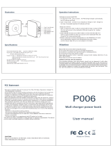
Figure 1.17 - Rheostatic braking
This alternative consists in connecting a resistor through a DC link at the
instant of the braking. Thus the energy that would be returned to the DC
link will be dissipated in the form of heat. This is a simple solution, but
depending on the involved energy, it will be very expensive.
A more efficient solution is the return of the energy to the line. This can be
realized through the use of two antiparallel connected totally controlled
rectifier bridges, or through diode and thyristor bridges (Fig. 1.18).
The main disadvantage of this method is the harmonic distortion rate and
the variation of the displacement factor under load and all associated
problems.
If nothing is done, the voltage in the capacitors will increase until the
overvoltage protection device in the DC link trips out. So the IGBT´s output
pulses are shut down, the motor demagnetizes and stops to operate as
generator. The mechanical losses of the system (such as friction losses)
will bring the load to standstill (this time is proportional to the system
inertia). Many drives require a speed reduction or even a standstill within a
predetermined time without the presence of overvoltage in the DC link.
As the inertia acts as an energy accumulator, one can say that the faster
the energy generated by the motor is drained, the higher will be the braking
torque. Depending on the application (time to bring the motor to standstill,
or speed reduction) and on the cost of the energy that is returned to the
DC link circuit, there are several alternatives.
The first alternative is the DC current injection into the motor stator. The
inverter supplies the motor stator with DC current and as there is no rotating
field, no energy is returned. The currents induced into the rotor generates
resistive losses and the braking torque will be proportional to these losses.
As these losses are very low, this method is seldom used.
Other alternative is the injection of harmonics into the stator. As this
method generates high noises and as it shows a braking torque with high
ripples, it is not used so often.
The CFW-09 inverter line offers an additional option, that is the Optimal
Braking. When a braking is needed in the vector control mode, the inverter
maximize the motor losses, thus offering a high braking torque.
The most applied alternative is the rheostatic braking Fig. 1.17.
  • Page 1 1
  • Page 2 2
  • Page 3 3
  • Page 4 4
  • Page 5 5
  • Page 6 6
  • Page 7 7
  • Page 8 8
  • Page 9 9
  • Page 10 10
  • Page 11 11
  • Page 12 12
  • Page 13 13
  • Page 14 14
  • Page 15 15
  • Page 16 16
  • Page 17 17
  • Page 18 18
  • Page 19 19
  • Page 20 20
  • Page 21 21
  • Page 22 22
  • Page 23 23
  • Page 24 24
  • Page 25 25
  • Page 26 26
  • Page 27 27
  • Page 28 28
  • Page 29 29
  • Page 30 30
  • Page 31 31
  • Page 32 32
  • Page 33 33
  • Page 34 34
  • Page 35 35
  • Page 36 36
  • Page 37 37
  • Page 38 38
  • Page 39 39
  • Page 40 40
  • Page 41 41
  • Page 42 42
  • Page 43 43
  • Page 44 44
  • Page 45 45
  • Page 46 46
  • Page 47 47
  • Page 48 48
  • Page 49 49
  • Page 50 50
  • Page 51 51
  • Page 52 52
  • Page 53 53
  • Page 54 54

WEG Regenerative Converter CFW09 User manual

Type
User manual

Ask a question and I''ll find the answer in the document

Finding information in a document is now easier with AI