
ALA3800 ALUMINUM RACEWAY
Installation
Instructions
The ALA3800 is a permanent single-channel raceway that is versatile
enough to accommodate power, data or telecommunication wiring.
NOTE: Cross-sectional area of each compartment indicated.
Wiremold Electrical Systems conform with, and should be installed and properly grounded in compliance with requirements of the current
National Electrical Code or codes administered by local authorities.All electrical products may represent a possible shock or fire hazard if improp-
erly installed or used.Wiremold electrical products are UL listed, made for interior use in a dry location and should be installed by qualified elec-
trical people in conformance with current local and/or the National Electrical Code.
At 90° Outside Corner, position ALA3818
External Elbow at end of ALA3800B-10
Base. Slide other base section to other end
of ALA3818. Center couplings on joints
and tighten screws. After wiring system,
snap on ALA3818 mitered covers.
For retaining wires in long raceway
runs, snap-in ALAWC Series Wire Clips
into ALA3800B-10 Base approximately
30" [762mm] apart.
Snap ALA3806 Cover Clip over
joints in either ALA3800B Base or
ALAC-5 Cover sections.
ALA3815 Tee: Position fitting at end of ALA3800B-10 Base. Install
other base sections to other ends of the fitting. Center couplings on
joints and tighten screws. Install fitting covers after wiring.
ALAWC
ALA3815
The Wiremold Company
In U.S.:
60 Woodlawn Street • West Hartford, CT 06110
1-800-621-0049 • FAX 860-232-2062
In Canada:
850 Gartshore Street • Fergus, Ontario N1M 2W8
1-800-741-7957 • FAX 519-843-5980
41400 298©1998 The Wiremold Company
For Device Plates (ALA-BL, ALA-E, ALA-DR, ALA-G, ALA-J, ALA-N, ALA-LPB,
ALA-MAB, ALA-SG, ALA-2A, and ALA-Z), install wiring to devices as required.
Attach devices to plate (using #6 screws and "Keps" nuts as required.) Snap
device plate onto ALA3800B-10 Raceway Base.
*Capacity range is calculated at 20% to 40% of raceway area as stated in a proposed revisions to the Commercial Building Standard for
Telecommunication Pathways & Spaces, EIA/TIA-569. Actual wire fill capacity may vary based on applications, cable types, and number, as well as
type of fittings. (Fittings may cause additional variances to the fill capacity.)
CABLE/WIRE SIZE O.D. 20% FILL 40% FILL
INCHES [MM]
UNSHIELDED TWISTED PAIR 4-Pair, 24 AWG Cat. 5 0.220 [5.6] 31 62
4-Pair, 24 AWG Cat. 3 0.190 [4.8] 41 83
TELEPHONE 2-Pair, 24 AWG 0.140 [3.6] 77 154
3-Pair, 24 AWG 0.150 [3.8] 67 134
4-Pair, 24 AWG 0.190 [4.8] 41 83
25-Pair, 24 AWG 0.410 [10.4] 8 17
COAXIAL CABLES RG58/U 18 0.195 [5.0] 39 79
RG59/U 22 0.242 [6.1] 25 51
RG62/U 20 0.242 [6.1] 25 51
RG6/U 22 0.270 [6.9] 20 41
TWINAXIAL 100 Ohm 0.330 [8.4] 13 27
SHIELDED TWISTED PAIR TYPE 1 0.390 [9.9] 9 19
TYPE 2 0.465 [11.8] 6 13
TYPE 3 0.245 [6.2] 25 50
FIBER OPTIC Two Strand (Duplex) 0.190 [4.8] 41 83
Multimode 62.5/125 µm
WIRE SIZE THHN/THWN O.D. 40% FILL
INCHES [MM]
6 AWG 0.257 [6.5] 41
POWER WIRING 8 AWG 0.218 [5.5] 56
WITHOUT DEVICES 10 AWG 0.153 [3.9] 98
12 AWG 0.122 [3.1] 156
14 AWG 0.105 [2.7] 214
6 AWG 0.257 [6.5] 30
POWER WIRING 8 AWG 0.218 [5.5] 42
WITH DEVICES 10 AWG 0.153 [3.9] 73
12 AWG 0.122 [3.1] 116
14 AWG 0.105 [2.7] 159
ALA3800 Raceway Cable Fill Capacity for Power
ALA3800 Raceway Cable Fill Capacity for Data/Communication
3"
[76mm]
2 1/4"
[57mm]

ALA3800B Base
(ALA3810B shown)
3/4" [19.1mm] Conduit
1/2" [12.7mm] Conduit
End-feeding: ALA3810B1 Series End Fittings
have concentric 1/2" [12.7mm] and 3/4"
[19.1mm] trade size KOs in end. Provide
electrical feed through KOs. Insert fitting into
end of raceway base. Secure in place by
tightening two screws.
3
4
6
5
1
2
1 - Provide electrical feed through the concentric 1/2" [12.7mm]
and 3/4" [19.1mm] KO in ALA3810B1 End Cap.
2 - Attach base section to mounting surface by drilling
9/32" [7.14mm] holes in the base then fastening with
#8 flat head screws.
3 - Secure conductors in place with ALAWC Wire Clip.
4 - Join additional raceway sections with an ALA01 Coupling.
5 - Close ends with ALA3810B1 End Caps.
6 - Snap ALAC-5 Cover into ALA3800B-10 Base to
complete installation.
To attach ALA3800B-10 Series Base sections to mounting
surface; drill 9/32" [7.14mm] holes in the base (approx.
18" [457mm] O.C.). Fasten Base with #8 flat head screws.
18"
[457mm]
At end of ALA3800B-10 Raceway
run: slide ALA3810B Blank End
Fitting in last base section. Secure in
place by tightening two screws.
ALA01
ALA3800B-10
Base Sections
At ALA3800B-10 Base section butt joints: slide an ALA01
Coupling into first base section. Mount next base to surface.
Center coupling on joint. Tighten locking screws.
Position ALA09 Ground Clamp
into ribs in ALA3800B-10 Base.
Fasten mounting screw. Attach
ground wire using brass cup
washer & green hex nut to
ground lug.
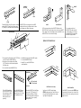
At 90° turn on same surface, position ALA3811 Flat Elbow at end of
ALA3800B-10 Base. Position next base section onto other end of ALA3811.
Center coupling over base joint and tighten screws. Install ALA3811 Covers
and ALA3800 Series Covers as shown after wiring.
For connecting a vertical run of
ALA3800B-10 Base with a horizontal
overhead run with its cover facing up.
Assemble ALA3817N to raceway bases
with ALA01 Couplings included.
Install one side of ALA17A Internal Coupling,
BEFORE mounting raceway base. Fasten first base sec-
tion to wall, then slide adjoining base onto coupling
legs. Tighten all coupling screws.
Install ALA3817 to first raceway base, BEFORE mount-
ing raceway base. Fasten base section to surface. Butt
next section of base. Center couplings over base joints,
tighten set screws.
ALA3811
ALA3811 With Cover
ALA17A Internal Corner Coupling
ALA3817 Internal Elbow
Options for 90° Internal Corners:
System Layout
ALA3817N
-
 1
1
-
 2
2


Ask a question and I''ll find the answer in the document
Finding information in a document is now easier with AI
Related papers
-
Legrand ALA-SG Installation guide
-
Legrand NM20IG612 Operating instructions
-
Legrand 5010AGY Installation guide
-
Legrand 700WH Installation guide
-
Legrand AL3300WC Operating instructions
-
-
Legrand BK20GB506TRGFI6 Installation guide
-
-
Legrand Fiber Optic Fittings Installation guide
-
Legrand AL5201 Operating instructions
Other documents
-
FSR SW-WT-FC Installation guide
-
-
FSR SW Raceway Floor System Installation guide
-
Etman 52120 Owner's manual
-
Legrand Wiremold OFRBC-8R Specification
-
 Wiremold Legrand C910 Specification
-
Hubbell Wiring Device-Kellems PD2212 Installation guide
-
Carlon A243F-CAR User manual
-
Wiremold V5738AF User manual
-
