Page is loading ...

A
ttention :
1
. Utiliser seulement sur 120 V c.a. 60 Hz.
2
. Ne pas dépasser les 600 W de puissance maximale du gradateur.
3
. Réservé seulement aux installations incandescentes ou lampes halogènes
1
20 V c.a. montées de façon permanente. Pour éviter le surchauffement et des dégâts
causés à d’autres équipements, ne pas utiliser pour régler les prises de courant, les lampes
fluorescentes, les appareils à moteur, les appareils alimentés par transformateur, etc.
4. On ne peut utiliser qu’un seul gradateur dans un circuit va-et-vient. L’interrupteur
situé à l’opposé allume la lumière au niveau d’intensité choisi au gradateur.
5. Doit être installé conformément aux codes national et local de l’électricité.
6
. N’utilisez que du fil de cuivre avec ce dispositif.
Important : Déclencher le disjoncteur ou enlever le(s) fusible(s) et vérifier que le courant est
coupé avant de câbler. Ne jamais câbler un appareil électrique sans couper le courant. Le
câblage sous tension du gradateur risque de lui causer des dégâts irréparables.
I
NSTALLATION
L
ire chaque étape attentivement et procéder dans l’ordre.
INSTALLATIONS AVEC D’AUTRES APPAREILS :
Si vous installez un gradateur 1000 W (RI101) avec d’autres appareils dans une boîte pour groupe
d
e deux ou plus, procédez comme suit :
•
Il se peut qu’il vous faille enlever les sections latérales de la barrette de montage. À l’aide d’une
pince, pliez soigneusement les sections latérales avec un mouvement de va-et-vient jusqu’a ce
q
u’elles se cassent.
• Si on enlève les sections latérales dans les installations avec plusieurs gradateurs, il faut réduire
la capacité du gradateur. Reportez-vous au tableau 1 pour la charge maximale par gradateur
permise dans les installations groupées.
REMARQUE : il n’est pas nécessaire de réduire la puissance maximale quand on groupe des
gradateurs de 600 W de puissance nominale.
INSTRUCTIONS : CÂBLAGE D’UN NOUVEAU CIRCUIT :
(Sauter au paragraphe suivant en cas de remplacement d’un interrupteur existant.)
Câbler le circuit comme pour un interrupteur normal (voir Fig. 1 ou 2). Avant d’installer le
gradateur, il est conseillé de contrôler le circuit en installant un interrupteur standard à la place
du gradateur. Ceci évite d’endommager le gradateur en cas de courts-circuits, d’erreurs de
câblage, de surcharges, etc.
1. Torsadez ensemble les extrémités nues de chaque paire de fil, selon le schéma.
2. Enfoncer fermement les deux paires de fils dans les connecteurs fournis.
3. Tourner le connecteur en sens horaire jusqu’à ce qu’il soit serré et qu’il n’y ait plus de cuivre
visible. Fixer les fils et les connecteurs avec du ruban adhésif d’électricien.
4.
Tourner le connecteur en sens horaire jusqu’à ce qu’il soit serré et qu’il n’y ait plus de
cuivre visible. Fixer les fils et les connecteurs avec du ruban adhésif d’électricien.
5. (a) Raccordez un des fils débranchés de l’interrupteur sur un des fils noirs du gradateur à
l’aide du connecteur de câblage fourni.
(b) Raccordez l’autre fil débranché de l’interrupteur sur l’autre fil noir du gradateur à l’aide
du connecteur de câblage fourni.
(c) Raccordez le fil de terre sur le fil vert du gradateur à l’aide du connecteur de câblage
fourni.
6. Ôter le bouton de l’avant du gradateur, enfiler la plaque murale sur la tige du gradateur et
remonter le bouton sur la tige. Fixer la plaque murale à l’appareil.
7. Remettre le fusible ou réarmer le disjoncteur.
POUR REMPLACER UN INTERRUPTEUR EXISTANT
1. Enlever la plaque murale.
2. Enlever l’interrupteur existant.
Continuer au paragraphe approprié ci-dessous (unipolaire ou trois voies).
POUR SYSTÈMES UNIPOLAIRES :
3. Débrancher les fils de l’interrupteur existant.
4. Redresser ou couper les extrémités des fils pour qu’elles soient droites.
5. Dénuder les fils si nécessaire de manière à ce que .95 cm de cuivre soit visible.
6. Branchez le gradateur comme indiqué à la figure 1.
7. (a) Raccordez un des fils débranchés de l’interrupteur sur un des fils noirs du gradateur à
l’aide du connecteur de câblage fourni.
(b) Raccordez l’autre fil débranché de l’interrupteur sur l’autre fil noir du gradateur à l’aide
d
u connecteur de câblage fourni.
(c) Raccordez le fil de terre sur le fil vert du gradateur à l’aide du connecteur de câblage
f
ourni.
Continuer à l’étape 8 ci-dessous.
POUR SYSTÈMES À 3 VOIES :
3. Choisissez lequel des va-et-vient sera remplacé par le gradateur. En général, ce sera celui
situé là où vous voulez normalement commander l’intensité de l’éclairage.
4. Le fil raccordé à la borne commune est identifié par un repère qui indique COM, ou alors la
couleur de la vis est noire et différente de celle des deux autres vis. Étiquetez le fil commun.
Débranchez le va-et-vient qui sera remplacé par le gradateur.
5. Raccordez le gradateur comme indiqué à la figure 2.
5a. Raccordez le fil commun étiqueté sur le fil noir à l’aide des connecteurs de
câblage fournis.
5b. Raccordez le fil rouge du gradateur sur un des autres fils débranchés de l’interrupteur.
5c. Raccordez le fil jaune du gradateur sur le fil débranché de l’interrupteur restant.
5d. Raccordez le fil de terre au fil vert du gradateur.
Continuer à l’étape 8 ci-dessous.
POUR SYSTÈMES UNIPOLAIRES ET À 3 VOIES
8. Enfoncer doucement les fils et les connecteurs dans le boîtier mural.
9. Enfoncer doucement le gradateur dans le boîtier mural et l’y fixer à l’aide des vis de
montage. S’assurer que le gradateur est placé de manière à ce que le symbole «TOP» qui est
gravé sur la languette métallique soit en haut.
10. Ôter doucement le bouton de l’avant du gradateur, enfiler la plaque murale sur la tige du
gradateur et remonter le bouton sur la tige du gradateur. Fixer la plaque murale au boîtier
mural.
11. Remettre le fusible ou réarmer le disjoncteur.
REMARQUE : Il n’est pas nécessaire de diminuer la puissance maximale quand plusieurs
gradateurs sont montés dans le même boîtier mural.
C
aution:
1
. Use only with 120V AC 60 Hz.
2
. Do not exceed maximum rating of the dimmer as indicated on the strap.
3. For use only with permanently installed fixtures, using 120V AC incandescent or 120V AC
halogen lamps only. To avoid overheating and possible damage to other equipment, do not
use to control receptacles, fluorescent lights, motor-driven appliances, transformer-supplied
appliances, etc.
4
. Only one dimmer can be used in a 3-way circuit. The switch on the other end
w
ill turn on at the brightness level selected at the dimmer.
5
. Must be installed and used in accordance with electrical codes.
6
. Use only copper wire with this device. Do not use with aluminum wire.
Important: Turn circuit breaker to OFF or remove fuse(s) and test that power is off before wiring.
Never wire any electrical device with power turned on. Wiring dimmer hot may cause permanent
damage to dimmer.
I
NSTALLATION:
Read each step carefully and perform in sequence.
MULTI-DEVICE INSTALLATIONS:
I
f installing a 1000 Watt dimmer (TI3101, TI3101L) in a multi-device installation in a 2 or more gang
box proceed as follows:
• The side sections of the mounting strap may require removal. Use pliers to carefully bend side
sections back and forth until they break off.
• Removal of the side sections in multi-dimmer installation requires a reduction of the dimmer’s
capacity. Refer to Table 1 for maximum load per dimmer for multi-ganging.
NOTE: No derating is required when ganging multiple dimmers rated 600W.
INSTRUCTIONS: NEW CIRCUIT WIRING:
(Skip to next section if replacing an existing switch.)
Wire circuit as you normally would for a switch application (see Figure 1 or 2). Before installing
the dimmer, it is advisable to test the circuit with a standard wall switch installed in place of the
dimmer. This prevents accidental damage to the dimmer from shorts, miswires, overloads, etc.
1. Strip wires in wall box to expose 3/8" of copper on the end of each wire.
2. Twist bare ends of each pair of wires together, per diagram.
3. Push each wire pair firmly into one of the wire connectors provided.
4. Twist the wire connector clockwise until snug and no copper is showing. Secure wires and
connector with electrical tape.
5. Gently push wires and wire connectors into wall box.
6. Gently push dimmer into wall box and secure, using mounting screws. Ensure that dimmer is
positioned so that symbol “TOP” stamped into metal strap appears at top.
7. Place wallplate over dimmer. Secure wallplate to dimmer (Figure 3).
8. Replace fuse(s) or turn on circuit breaker.
TO REPLACE EXISTING SWITCH:
1. Turn off power.
2. Pull out the switch.
Proceed to appropriate section below (Single-Pole or 3-Way)
FOR SINGLE-POLE APPLICATIONS:
3. Disconnect wires from existing switch.
4. Straighten or clip ends of wires such that ends of each wire are straight.
5. Strip insulation if necessary to expose 3/8" of copper on the end of each wire.
6. Connect the dimmer as shown in Figure 1.
7. (a) Cap the yellow wire with one of the wire connectors provided.
(b) Connect one of the wires removed from the switch to the dimmer black wire using the
wire connect provided.
(c) Connect one of the wires removed from the switch to the dimmer red wire with the wire
connector provided.
(d) Connect the ground wire to green dimmer with the wire connector provided.
Proceed to Step 8.
FOR 3-WAY APPLICATIONS:
3. Select which 3-way
s
witch will be replaced by the dimmer. This will typically be the location that you would normally
w
ant to control the dim level.
4. The wire connected to the common terminal is identified by a marking indicating COM, or the
s
crew color is black, and different than the other two screws. Tag the common wire.
Disconnect the 3-way switch that will be replaced by the dimmer.
5. Connect the dimmer as shown in Figure 2.
5a. Connect the tagged common wire to the black wire using the wire connector provided.
5b. Connect the red dimmer wire to one of the other wires removed from the switch.
5c. Connect the yellow dimmer wire to the remaining wire removed from the switch.
5d. Connect the ground wire to the green dimmer wire with the wire connector provided.
6 . Proceed to Step 8.
FOR SINGLE-POLE AND 3-WAY APPLICATIONS:
8. Gently push wires and wire connectors into wall box.
9. Gently push dimmer into wall box and secure, using mounting screws. Ensure that dimmer is
positioned so that symbol “TOP” stamped into metal strap appears at top.
10. Place wallplate over dimmer. Secure wallplate to dimmer (refer to Figure 3).
11. Replace fuse(s) or turn on circuit breaker.
OPERATION
SINGLE POLE:
Raise toggle to increase light level. Lower toggle
to decrease light level. Lower toggle to lowest
position to turn lights off. On TI061L and TI306L,
night light will turn on when lights are turned off.
3-WAY SWITCH:
When the 3-Way switch toggle is in one position
(might be up or down), lights may be dimmed to
the desired level at the 3-way dimmer. When the
3-way switch toggle is in the opposite position,
dimmer acts as an “ON/OFF” switch. On TI306L,
TI061L and TI3101L, night light will turn on when
lights (bulbs) are turned off.
T
OGA-PTA (REV. C)
ENGLISH I
N U.S.A.: Cooper Wiring Devices, 203 Cooper Circle, Peachtree City, GA 30269 • 866-853-4293
TI306-K, TI306L (600W 3-WAY) TI061, TI061L (600W SP/3W) TI061-K, TI061L-K (600W SP) TI3101, TI3101L (1000W SP/3W)
INCANDESCENT 120V 60 Hz
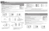
FIG. 1: FOR SINGLE POLE APPLICATIONS
HOT
120V AC
N
EUTRAL
WHITE
BLACK
RED
LOAD
BLACK
GREEN
YELLOW
LI
S
T
E
D
3K
/
2
R
M
O
D
E
L
FIG. 3
R
emove all inner side sections
DO NOT remove
outer side
s
ections
Bend back and
forth to remove
s
ide section
OFF
HOT
120V AC - 60 Hz
NEUTRAL
FOR 3-WAY APPLICATIONS
BLACK
FIG. 2
RED
YELLOW
BLACK
TAG
LOAD
SWITCH
WHITE
DIMMER
GREEN
GANG 1000W MODELS (TI3101, TI3101L)
1 No Derating
2 900W max.
3 or more 800W max.
FRANÇAIS IN CANADA: Cooper Wiring Devices, 5925 McLaughlin Road, Mississauga, Ontario L5R 1B8 • 800-267-1042
MODELES TI306-K, TI306L (600 W 3-VOIES) TI061, TI061L (600W UNIPOLAIRE /3-VÍAS)
TI061-K, TI061L-K (600W UNIPOLAIRE) TI3101, TI3101L (1000W SP/
3-VOIES) INCANDESCENT 120V 60 Hz
Enlevez toutes les sections
latérales internes
N
’enlevez PAS les
sections latérales
e
xternes
Plier la section
latérale avec un
m
ouvement de
va-et-vient
p
our l’enlever
GANG 1000 W MODELES (TI3101, TI3101L)
1 Aucune sous-sollicitation
2 900W max.
3 ou plus 800W max.
FIG. 1: APPLICATIONS UNIPOLAIRE
PHASE
120V c.a.
NEUTRE
BLANC
NOIR
ROUGE
CHARGEMENT
NOIR
VERTE
JAUNE
OFF
PHASE
120V c.a. - 60 Hz
NEUTRE
APPPLICATIONS DE 3 VOIES
NOIR
FIG. 2
ROUGE
JAUNE
NOIR
ETIQUETTE
CHARGEMENT
INTERRUPTEUR
BLANC
GRADATEUR
VERTE
/