Page is loading ...

INSTRUCTIONS D’INSTALLATION
Attention :
1. Fonctionne uniquement en 120 V C.A. 60 Hz.
2. Ne dépassez pas le courant nominal maxi de 5 A de la
commande de ventilateur.
3. S’utilise avec des moteurs à condensateur de déphasage
ou à bague de déphasage montés de manière permanente
comme ceux des ventilateurs de plafond. Pour éviter une
surchauffe et des dégâts éventuels sur d’autres appareils,
n’utilisez pas cet appareil pour commander des prises, des
éclairages fluorescents, des appareils alimentés par
transformateur, etc.
4. Doit être installé selon les règlements électriques
nationaux et locaux.
5. Utilisez uniquement du fil de cuivre sur cet appareil.
6. Compatible avec les boites de prise en métal ou en
plastique.
MISE EN GARDE : Coupez le courant au disjoncteur ou
enlevez le ou les fusibles et contrôlez que le courant est
coupé avant de câbler. Il ne faut jamais câbler d’appareil
électrique sous tension. Le câblage de la commande de venti-
lateur sous tension risque de l’endommager.
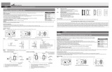
IMPORTANT :
Veuillez lire attentivement toutes les étapes et les effectuer
dans l’ordre. Câblez le circuit comme vous le feriez
normalement pour un interrupteur (voir figures). Avant
d’installer la commande de ventilateur, il est conseillé de
tester le circuit avec un interrupteur ordinaire installé à la
place de la commande de ventilateur. Ceci évite d’abîmer
accidentellement la
commande de ventila-
teur en cas de court
circuit, de câblages
incorrect, de sur-
charges, etc.
Pour effectuer les
raccordements
mentionnés, torsadez
ensemble les
extrémités dénudées
de chaque paire de fils, comme indiqué aux schémas. Puis,
enfoncez fermement chacune de ces paires dans un des
connecteurs de câblage fournis et vissez ce dernier en sens
horaire jusqu'à ce qu’il soit serré et que le cuivre ne soit plus
visible. Fixez les connecteurs aux fils avec du ruban adhésif
isolant.
INSTRUCTIONS DE CÂBLAGE
1. Coupez le courant à la boîte de fusible ou au disjoncteur.
2. Si vous remplacez un interrupteur existant, enlevez la
plaque murale et l’interrupteur et débranchez les fils.
3. Si nécessaire, redressez ou coupez les extrémités des fils
pour qu’elles soient bien droites.
4. Dénudez les fils de la boîte murale de manière à exposer
3/8 po de cuivre à leur extrémité.
5. Raccordez les fils comme indiqué au schéma approprié
(commande de ventilateur ou ventilateur à l’extrémité du
circuit). Voir Fig. 2 et 3.
6. Raccordez le fil vert de la commande de ventilateur au fil
de terre de la boîte murale à l’aide d’un connecteur de
câblage ou raccordez-le à la vis de terre située dans la
boîte murale.
7. Poussez délicatement les fils avec les connecteurs de
câblage et la commande de ventilateur dans la boîte
INSTALLATION INSTRUCTIONS
Caution:
1. Use only with 120V AC 60 Hz.
2. Do not exceed 5 Amp max. current rating of the fan control.
3. For use with permanently installed split capacitor or
shaded pole motors used in ceiling fans. To avoid
overheating and possible damage to other equipment, do
not use to control receptacles, fluorescent lights,
transformer-supplied appliances, etc.
4. Must be installed in accordance with national and local
electrical codes.
5. Use only copper wire with this device.
6. Suitable for use in metal or plastic outlet boxes.
WARNING: Turn circuit breaker to OFF or remove fuse(s) and
test that power is off before wiring. Never wire any electrical
device with power turned on. Wiring fan control hot may
cause permanent damage to fan control.
IMPORTANT:
Read each step carefully
and perform in
sequence. Wire circuit
as you normally would
for a switch application
(see Figures). Before
installing the fan control,
it is advisable to test the
circuit with a standard
wall switch installed in
place of the fan control.
This prevents accidental
damage to the fan
control from shorts, miswires, overloads, etc. Where
instructed to make a connection, twist bare ends of each pair
of wires together as shown in diagrams. Then push each wire
pair firmly into one of the wire connectors provided and twist
the wire connector clockwise until snug and no copper is
showing. Secure connector to wires with electrical tape.
WIRING INSTRUCTIONS
1. Turn OFF power at fuse box or circuit breaker.
2. If replacing an existing switch, remove wallplate and
switch and disconnect wires.
3. If necessary, straighten or clip ends of wires such that
ends of each wire are straight.
4. Strip wires in wall box to expose 3/8” of copper on the end
of each wire.
5. Connect wires as shown in the appropriate diagrams (Fan
Control or Fan at end of line). See Fig. 2 or Fig. 3.
6. Connect green wire from fan control to ground wire in
wall box using wire connector or connect to ground screw
in wall box.
7. Gently push wires with wire connectors and fan control
into wall box and secure, using mounting screws. Ensure
that fan control is positioned so that symbol “TOP”
stamped into metal strap appears at top.
8. Secure wallplate to fan control.
9. Replace fuse or turn on circuit breaker.
OPERATION
Raise toggle to increase fan speed. Lower toggle to decrease
fan speed. Push toggle to lowest position to turn fan off.
GANGING
Derating is not required when ganging multiple fan controls in
one wallbox.
Wire connectors provided may be used
on the following wire combinations:
T
FSA-PTA (REV. A)
ENGLISH I
N U.S.A.: Cooper Wiring Devices, 203 Cooper Circle, Peachtree City, GA 30269 • 866-853-4293
TOGGLE FAN CONTROL WITH NON-PRESET — TFS5
FRANÇAIS I
N CANADA: Cooper Wiring Devices, 5925 McLaughlin Road, Mississauga, Ontario L5R 1B8 • 800-267-1042
COMMANDE DE VENTILATEUR À BASCULEUR — TFS5
HOT
1
20V AC
NEUTRAL
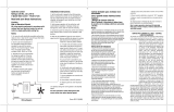
FIG. 1 FOR SINGLE POLE APPLICATIONS
BLACK
LEADS
FROM
FAN CONTROL
F
AN
LOAD
CHARGÉ
120V c.a.
NEUTRE
FIG. 1: POUR APPLICATIONS UNIPOLAIRES
FILS NOIR
PROVENANT
AU
GRADATEUR
CHARGE
(VENTILATEUR)
FIG. 2 FAN CONTROL AT END OF LINE
GREEN (TO GREEN
OR BARE GROUND WIRE)
HOT
(BLACK)
NEUTRAL
(WHITE)
TWO BLACK
WIRES
LI
STED
3K/
2
R
M
ODEL
FIG. 2: UNIPOLAIRE AVEC COMMANDE DE
VENTILATEUR EN BOUT DE LIGNE
VERT (VERS FIL
DE TERRE VERT OU NU)
CHARGÉ
(NOIR)
NEUTRE
(BLANC)
DEUX FILS
NOIRS
FOR PERMANENT INSTALLATION
WITH INCAND. LOAD ONLY
120 VAC, 600W. MAX.
LIS
T
E
D
3K
/2
R
MO
D
EL
FIG. 3 FAN AT END OF LINE
G
REEN (TO GREEN OR
B
ARE GROUND WIRE)
BLACK
WIRES
NEUTRAL
(WHITE)
HOT
(BLACK)
LI
S
T
E
D
3K
/
2
R
MO
D
EL
FIG. 4 MINIMUM SPEED ADJUSTMENT
L
IS
T
E
D
3
K
/
2
R
M
O
D
E
L
MIMIMUM
SPEED
ADJUSTMENT
MINIMUM SPEED ADJUSTMENT:
1
. With the wall plate removed, lower toggle to minimum
speed.
2. Using a small screwdriver, turn speed adjustment control on
the strap (see Fig. 4) fully counterclockwise.
3. If the fan is rotating the adjustment may be left in this
position. If a faster minimum speed is desired, then turn
clockwise until the desired speed is reached.
4. If the fan is not rotating, turn the adjustment clockwise until,
as a minimum, the fan begins to rotate. Turn the adjustment
farther clockwise if a faster minimum speed is desired.
5. Replace the wallplate.
2 #14
2 or 3 #16
2 to 5 #18
3 #16 with 1 #18
1 #14 with 1 or 2 #16
2 #16 with 1 or 2 #18
1 #14with 1 to 3 #18
/