Page is loading ...

HD-703/HD-1103
Incandescent Preset Paddle Dimmer, 3-Way
Gradateur d'éclairage à palette préréglé à incandescence, 3 Voies
Regulador de paleta preestablecido incandescente, 3 Vias
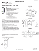
MULTIPLE GANGING OF DIMMERS AND OTHER DEVICES
Any combination of dimmer models and other devices may be ganged together. Break off tabs are
provided on the 1000W dimmer straps for multi-gang applications. Pry off the tabs using pliers before
installation, as shown in figure 2. De-rate the maximum load according to the following table:
Dimmer Catalog # Maximum Load
Multi-Gang Derating
2 Gang Installation 3 Gang Installation
HD-1103 1100 W 1000 W 800 W
Figure 2
REMARQUES IMPORTANTES
1. Tous les gradateurs peuvent être endommagés par un câblage incorrect. Avant d’installer le
gradateur, vérifier qu’il n’y a pas de court-circuit en utilisant une lampe.
Comment vérifier l’absence de court-circuit :
a. Couper l’alimentation du circuit en retirant le fusible ou en ouvrant les disjoncteurs (ARRÊT /
OFF).
b. Installer un interrupteur à la place du gradateur. Mettre l’interrupteur en position fermée
(MARCHE / ON).
c. Rétablir l’alimentation électrique. Si le disjoncteur saute, c’est qu’il existe un court-circuit. Si la
lumière ne s’allume ou ne s’éteint pas correctement, le câblage peut être incorrect.
d. Rectifier le câblage si besoin est, et retester le circuit.
e. Installer le gradateur uniquement si la lumière fonctionne correctement avec l’interrupteur.
2. Protéger le dispositif de la saleté et de la poussière. Le gradateur peut être endommagé par
des débris laissés au cours de la construction. S’il est nécessaire d’avoir une source d’éclairage
avant la fin de la construction, installer provisoirement un interrupteur à la place du gradateur. Le
gradateur ne doit pas être installé avant la fin de la construction.
Aucun gradateur endommagé par une installation incorrecte n’est couvert par la garantie.
INSTRUCTIONS
1. S’il est nécessaire de changer de couleur et qu’un ensemble de changement de couleur est
disponible, se reporter à la Procédure de changement de couleur; sinon, passer à l’étape n° 2.
2. Couper l’alimentation du circuit en retirant le fusible ou en ouvrant les disjoncteurs (ARRÊT/OFF)
avant de commencer l’installation.
3. Retirerlesvisdexationdelaplaquemuraleetdel’interrupteur,puisretirerl’interrupteurdela
boîte murale.
4. Déconnecterl’interrupteurexistantducircuit.Installation3voies:Identierlelcommun(le
lconnectéàlabornemarquée«Common/Commun»oudecouleurparticulière).Pourles
nouvellesinstallations,identierlelconnectéàlasourcedecourantouàlacharge.
5. Connecter le gradateur comme illustré sur le schéma de câblage en utilisant des conducteurs
en cuivre massifs ou torsadés de calibre 12 ou 14 AWG. Dénuder les fils en utilisant le gabarit
reproduit au dos de l’unité. (Figure 1)
SCHÉMA D’INSTALLATION DES GRADATEURS
IMPORTANT NOTES
1. All dimmers can be damaged by improper wiring. Check for short circuits prior to installing the
dimmer with a lamp load in the circuit.
Procedure for short circuit check:
a. Disconnect power to circuit by removing fuse or turn circuit breakers OFF.
b. Install a switch instead of the dimmer. Turn the switch to the “ON” position.
c. Turn power ON. If the circuit breaker trips, a short is present. If the light fails to turn ON and
OFF with the switch, the wiring may be incorrect.
d. Correct wiring, if necessary and retest.
e. Install the dimmer only after the light operates properly with the switch.
2. Protect from dirt and dust. The dimmer can be damaged from contaminates encountered during
the construction process. If lighting is required prior to the construction process completion, then a
switch should be temporarily installed in place of the dimmer. The dimmer should not be installed
until the construction process is complete.
Any dimmer damage due to improper installation is not covered under warranty.
COLOR CHANGE PROCEDURE/PROCÉDURE DE CHANGEMENT DE COULEUR/
PROCEDIMIENTO DE CAMBIO DE COLOR
DIRECTIONS
1. If a color change kit was provided, and a different color is desired, see the Color Change
Procedure, if not proceed to step #2.
2. Disconnect power to circuit at the panel by removing fuse or turn circuit breakers OFF before
installing.
3. Remove wall plate and switch mounting screws, pull existing switch from wall box.
4. Disconnect existing switch from circuit. 3-Way Installation: Identify the “COMMON” wire (wire
connected to the terminal marked common or odd colored terminal). For “new” installation identify
wire connected to power source or to the load.
5. Connect dimmer as shown in the installation diagram using #12 or #14 AWG stranded or solid
copper conductors. Strip wire using gauge on back of device. (Figure 1)
INSTALLATION DIAGRAM FOR DIMMERS
Figure 1
6. Install dimmer in wall box, with word ‘TOP’ on the strap right side up, using mounting screws
provided.
7. Attach wall plate and restore power to circuit.
Commun vers
l’interrupteur
3 voies
1
Raccorder
à la source
120 VCA 60 Hz
2
Commun vers
l’interrupteur
3 voies
3
Fil de Terre
(vert ou nu)
4
2
3
1
4
1
3
2
4
Raccorder
à la lampe
120 VCA 60 Hz
1
Raccorder
à la source
120 VCA 60 Hz
2
Ne rien brancher
sur cette borne
3
Fil de Terre
(vert ou nu)
4
Unipolaire 3 voies
READ AND SAVE THESE INSTRUCTIONS
To be installed by a certified electrician or other qualified
person.
WARNING – To prevent severe shock or electrocution,
always turn power off at the service panel before installing
this unit, working on the circuit, or changing a lamp.
CAUTION – To reduce the risk of overheating and possible
damage to other equipment, do not install incandescent
dimmer to control a receptacle, a fluorescent light or bulb,
a motor-operated appliance, or a transformer-supplied
appliance.
• Donotusedimmerwithincandescentlampswhosepower
requirements exceeds maximum power (stated in Watts) of
the dimmer.
• Donotconnectdimmertopowersourceotherthan
120VAC, 60 Hz only.
• A50Wminimumloadisrequired.
• Usecopperwireonly.
LIRE ET CONSERVER CES INSTRUCTIONS
Doit être installé par un électricien certifié ou une autre
personne qualifiée.
AVERTISSEMENT – Pour éviter tout choc électrique ou une
électrocution, toujours couper l’électricité au niveau du
panneau d’alimentation avant d’installer cette unité, de
travailler sur le circuit électrique ou de changer une lampe.
ATTENTION – Pour éviter toute surchauffe et endommagement
éventuel des autres appareils, ne pas utiliser pour contrôler
une prise, une lampe ou un tube fluorescent, ou un
appareil ménager équipé d’un moteur ou alimenté par un
transformateur.
• Nepasutilisercegradateuravecdeslampesà
incandescence d’une puissance supérieure à la puissance
maximale (exprimée en watts) de ce gradateur.
• Nepasconnectercegradateuràunesourcedecourant
autre que 120 VCA, 60 Hz.
• Doitalimenterunechargede50Wminimum.
• N’utiliserquedesfilsencuivre.
LEA Y CONSERVE ESTAS INSTRUCCIONES
Para ser instalado por un electricista certificado o persona
competente.
ADVERTENCIA – Para evitar descargas eléctricas serias
o electrocución, antes de instalar, trabajar en el circuito o
cambiar una lámpara de este atenuador apague siempre el
suministro eléctrico en el panel de servicio.
PRECAUCIÓN – Para reducir el riesgo de sobre calenta-
miento y posibles daños a otros equipos, no instale un
atenuador de lámparas incandescentes para controlar
un tomacorriente, una lámpara o bombilla fluorescente,
un electrodoméstico operado mediante motor o un
electrodoméstico equipado con transformador.
• Noutiliceatenuadoresconlámparasincandescentes
cuyos requerimientos de suministro eléctrico excedan la
potencia máxima (indicada en W) del atenuador.
• Noconecteelatenuadoraunsuministroeléctricodiferente
de 120VCA, 60 Hz.
• Serequiereunacargamínimade50W.
• Utiliceúnicamentealambresdecobre.
HD-703 HD-1103
Remove all fins
Remove inside fins only
3 GANG
INSTALLATION
2 GANG
INSTALLATION
INSTRUCTIONS EN FRANÇAIS
1.
2.
4.
5.
3.
6.
Traveler Wire to
3-Way Switch
1
Wire to Source
120VAC 60Hz
2
Traveler Wire to
3-Way Switch
3
Ground Wire
(Green or Bare)
4
1
3
2
4
2
3
1
4
Wire to Light
120VAC 60Hz
1
Wire to Source
120VAC 60Hz
2
Do not wire this
terminal
3
Ground Wire
(Green or Bare)
4
2
1
Screw Pressure Plate Back Wire
1
Insert wire to bottom of hole.
2
Securely tighten screw beneath wire hole to retain
inserted wire.
Termination takes #12 or #14 AWG stranded or solid,
copper conductors.
Single Pole 3-Way
SANTA CLARA, CA 95050
© 2013 WattStopper
SPECIFICATIONS • CARACTÉRISTIQUES • ESPECIFICACIONES
HD-703: 700 W, 120 VAC (VCA), 60 Hz HD-1103: 1100 W, 120 VAC (VCA), 60 Hz
Installation Instructions · Notice d'Installation · Instrucciones de Instalación
NOTE: Itisnormalforthedimmertofeelwarmduringoperation.Useaseparateneutralwireforeach
phase of a multiphase system containing a dimmer, and for high power single phase applications
where flickering is present.
/