Graco 3A8503G, Core E1 Electric Transfer Pump Operating instructions
- Category
- Paint Sprayer
- Type
- Operating instructions
This manual is also suitable for

3A8503G
EN
Operation, Repair, and Parts
Core™ E1 Electric Transfer Pump
For use with polyurethane foam, polyurea, and similar non-flammable materials. For use
with Reactor® 3 Systems only. For professional use only.
Not approved for use in explosive atmospheres or hazardous (classified) locations.
This product is not compatible with GFCI outlets. Electric motor controllers can cause
GFCI outlets to trip.
See page 3 for model information.
315 psi (2.17 MPa, 21.7 bar) Maximum Fluid Working Pressure
Important Safety Instructions
Read all warnings and instructions in this
manual before using the equipment.
Save these instructions.

2 3A8503G
Contents
Related Manuals . . . . . . . . . . . . . . . . . . . . . . . . . . . . 2
Models . . . . . . . . . . . . . . . . . . . . . . . . . . . . . . . . . . . . 3
Approvals . . . . . . . . . . . . . . . . . . . . . . . . . . . . . . . 3
Warnings . . . . . . . . . . . . . . . . . . . . . . . . . . . . . . . . . . 4
Important Isocyanate (ISO) Information. . . . . . . . . 6
Isocyanate Conditions . . . . . . . . . . . . . . . . . . . . . 6
Material Self-Ignition . . . . . . . . . . . . . . . . . . . . . . 7
Keep Components A and B Separate . . . . . . . . . 7
Moisture Sensitivity of Isocyanates . . . . . . . . . . . 7
Foam Resins with 245 fa Blowing Agents . . . . . . 7
Changing Materials . . . . . . . . . . . . . . . . . . . . . . . 7
Typical Installation . . . . . . . . . . . . . . . . . . . . . . . . . . 8
Typical Installation without Circulation. . . . . . . . . 8
Typical Installation with Circulation . . . . . . . . . . . 9
Typical Pump and Transfer Pump Controller
Installation . . . . . . . . . . . . . . . . . . . . . . . . . . 10
Typical Multiple Pump Lowers Installation. . . . . 11
Installation. . . . . . . . . . . . . . . . . . . . . . . . . . . . . . . . 12
Grounding . . . . . . . . . . . . . . . . . . . . . . . . . . . . . 12
Install the Transfer Pump Controller (TPC). . . . . 12
Pump Setup . . . . . . . . . . . . . . . . . . . . . . . . . . . . 14
Install the Pump . . . . . . . . . . . . . . . . . . . . . . . . . 14
Operation . . . . . . . . . . . . . . . . . . . . . . . . . . . . . . . . . 15
Flush Before Using Equipment. . . . . . . . . . . . . . 15
Pressure Relief Procedure . . . . . . . . . . . . . . . . . 15
Changing Material Drums. . . . . . . . . . . . . . . . . . 16
Using the Electric Motor. . . . . . . . . . . . . . . . . . . 17
Controlling the Pump . . . . . . . . . . . . . . . . . . . . . 17
Daily Startup. . . . . . . . . . . . . . . . . . . . . . . . . . . . 18
Daily Shutdown . . . . . . . . . . . . . . . . . . . . . . . . . 18
Pump Status LEDs . . . . . . . . . . . . . . . . . . . . . . . 19
Troubleshooting . . . . . . . . . . . . . . . . . . . . . . . . . . . 20
Maintenance . . . . . . . . . . . . . . . . . . . . . . . . . . . . . . 20
Monthly. . . . . . . . . . . . . . . . . . . . . . . . . . . . . . . . 20
Daily . . . . . . . . . . . . . . . . . . . . . . . . . . . . . . . . . . 20
Repair. . . . . . . . . . . . . . . . . . . . . . . . . . . . . . . . . . . . 21
Replace the Motor Cable . . . . . . . . . . . . . . . . . . 21
Replace the Encoder . . . . . . . . . . . . . . . . . . . . . 23
Replace the Guide Cover . . . . . . . . . . . . . . . . . . 24
Replace the Ball Screw Assembly . . . . . . . . . . . 25
Parts . . . . . . . . . . . . . . . . . . . . . . . . . . . . . . . . . . . . . 27
Pump (26D004). . . . . . . . . . . . . . . . . . . . . . . . . . 27
Electric Motor (25T322, 26D009) . . . . . . . . . . . . 28
Accessories . . . . . . . . . . . . . . . . . . . . . . . . . . . . 30
Electrical Connections . . . . . . . . . . . . . . . . . . . . . . 31
Dimensions . . . . . . . . . . . . . . . . . . . . . . . . . . . . . . . 32
Recycling or Disposal. . . . . . . . . . . . . . . . . . . . . . . 33
End of Product Life. . . . . . . . . . . . . . . . . . . . . . . 33
California Proposition 65 . . . . . . . . . . . . . . . . . . . . 33
Technical Specifications . . . . . . . . . . . . . . . . . . . . 35
Graco Extended Warranty for Reactor®
Components . . . . . . . . . . . . . . . . . . . . . . . . . . . 36
Related Manuals
Manuals are available at www.graco.com.
Manual in English Description
3A8500 Reactor 3 Proportioning Systems - Operation
3A8501 Reactor 3 Proportioning Systems - Repair and Parts
3A8598 ProConnect® CS Pump Lower - Parts
3A7683 Reactor 3 Proportioning Systems Heated Hose - Repair and Parts

Models
3A8503G 3
Models
Approvals
Part Description TPC
19B841
Pump
Lower
Material
Fluid Supply
Accessories Air Supply Accessories
Swivel
Fitting
157785
10 ft Fluid
Hose
217382
15 ft. Air
Hose, 1/4
npsm
210866
Nipple, 1/4
npt x 1/4
npsm
162453
Desiccant
Dryer Kit
247616
26D000 Core E1 Transfer Pump
Controller (TPC) ✓
26D004 Core E1 Pump
Carbon
Steel
26D005 Two Core E1 Pumps
with TPC ✓
26D006 Two Core E1 Pumps
with TPC and Fluid ✓ ✓ ✓
26D277 Two Core E1 Pumps
with TPC, Fluid, and Air ✓ ✓ ✓ ✓ ✓ ✓
Part Description
Approvals
19B841 Core E1 Transfer Pump
Controller (TPC) ✓ ✓ ✓ ✓
26D004 Core E1 Pump ✓ ✓
26D009 and
25T322 E1 Motor ✓ ✓
273295 ProConnect CS Pump Lower,
without bung adapter

Warnings
4 3A8503G
Warnings
The following warnings are for the setup, use, grounding, maintenance, and repair of this equipment. The
exclamation point symbol alerts you to a general warning and the hazard symbols refer to procedure-specific risks.
When these symbols appear in the body of this manual or on warning labels, refer back to these Warnings.
Product-specific hazard symbols and warnings not covered in this section may appear throughout the body of this
manual where applicable.
WARNING
TOXIC FLUID OR FUMES HAZARD
Toxic fluids or fumes can cause serious injury or death if splashed in the eyes or on skin, inhaled or
swallowed.
• Read Safety Data Sheets (SDSs) for handling instructions and to know the specific hazards of the
fluids you are using, including the effects of long-term exposure.
• When spraying, servicing equipment, or when in the work area, always keep work area
well-ventilated and always wear appropriate personal protective equipment. See Personal
Protective Equipment warnings in this manual.
• Store hazardous fluid in approved containers, and dispose of it according to applicable guidelines.
PERSONAL PROTECTIVE EQUIPMENT
Always wear appropriate personal protective equipment and cover all skin when spraying, servicing
equipment, or when in the work area. Protective equipment helps prevent serious injury, including
long-term exposure; inhalation of toxic fumes, mists or vapors; allergic reaction; burns; eye injury and
hearing loss. This protective equipment includes but is not limited to:
• A properly fitting respirator, which may include a supplied-air respirator, chemically impermeable
gloves, protective clothing and foot coverings as recommended by the fluid manufacturer and local
regulatory authority.
• Protective eyewear and hearing protection.
EQUIPMENT MISUSE HAZARD
Misuse can cause death or serious injury.
• Do not operate the unit when fatigued or under the influence of drugs or alcohol.
• Do not exceed the maximum working pressure or temperature rating of the lowest rated system
component. See Technical Specifications in all equipment manuals.
• Use fluids and solvents that are compatible with equipment wetted parts. See Technical
Specifications in all equipment manuals. Read fluid and solvent manufacturer’s warnings. For
complete information about your material, request Safety Data Sheets (SDSs) from distributor or
retailer.
• Do not leave the work area while equipment is energized or under pressure.
• Turn off all equipment and follow the Pressure Relief Procedure when equipment is not in use.
• Check equipment daily. Repair or replace worn or damaged parts immediately with genuine
manufacturer’s replacement parts only.
• Do not alter or modify equipment. Alterations or modifications may void agency approvals and
create safety hazards.
• Make sure all equipment is rated and approved for the environment in which you are using it.
• Use equipment only for its intended purpose. Call your distributor for information.
• Route hoses and cables away from traffic areas, sharp edges, moving parts, and hot surfaces.
• Do not kink or over bend hoses or use hoses to pull equipment.
• Keep children and animals away from work area.
• Comply with all applicable safety regulations.

Warnings
3A8503G 5
PRESSURIZED EQUIPMENT HAZARD
Fluid from the equipment, leaks, or ruptured components can splash in the eyes or on skin and cause
serious injury.
• Follow the Pressure Relief Procedure when you stop spraying/dispensing and before cleaning,
checking, or servicing equipment.
• Tighten all fluid connections before operating the equipment.
• Check hoses, tubes, and couplings daily. Replace worn or damaged parts immediately.
ELECTRIC SHOCK HAZARD
This equipment must be grounded. Improper grounding, setup, or usage of the system can cause
electric shock.
• Turn off and disconnect power at main switch before disconnecting any cables and before servicing
or installing equipment.
• Connect only to grounded power source.
• All electrical wiring must be done by a qualified electrician and comply with all local codes and
regulations.
MOVING PARTS HAZARD
Moving parts can pinch, cut or amputate fingers and other body parts.
• Keep clear of moving parts.
• Do not operate equipment with protective guards or covers removed.
• Equipment can start without warning. Before checking, moving, or servicing equipment, follow the
Pressure Relief Procedure and disconnect all power sources.
BURN HAZARD
Equipment surfaces and fluid that is heated can become very hot during operation. To avoid severe
burns:
• Do not touch hot fluid or equipment.
WARNING

Important Isocyanate (ISO) Information
6 3A8503G
Important Isocyanate (ISO) Information
Isocyanates (ISO) are catalysts used in two component materials.
Isocyanate Conditions
Spraying or dispensing fluids that contain isocyanates creates potentially harmful mists, vapors, and atomized
particulates.
• Read and understand the fluid manufacturer’s warnings and Safety Data Sheets (SDSs) to know specific
hazards and precautions related to isocyanates.
• Use of isocyanates involves potentially hazardous procedures. Do not spray with this equipment unless you
are trained, qualified, and have read and understood the information in this manual and in the fluid
manufacturer’s application instructions and SDSs.
• Use of incorrectly maintained or mis-adjusted equipment may result in improperly cured material, which could
cause off gassing and offensive odors. Equipment must be carefully maintained and adjusted according to
instructions in the manual.
• To prevent inhalation of isocyanate mists, vapors and atomized particulates, everyone in the work area must
wear appropriate respiratory protection. Always wear a properly fitting respirator, which may include a
supplied-air respirator. Ventilate the work area according to instructions in the fluid manufacturer’s SDSs.
• Avoid all skin contact with isocyanates. Everyone in the work area must wear chemically impermeable gloves,
protective clothing and foot coverings as recommended by the fluid manufacturer and local regulatory
authority. Follow all fluid manufacturer recommendations, including those regarding handling of contaminated
clothing. After spraying, wash hands and face before eating or drinking.
• Hazard from exposure to isocyanates continues after spraying. Anyone without appropriate personal
protective equipment must stay out of the work area during application and after application for the time period
specified by the fluid manufacturer. Generally this time period is at least 24 hours.
• Warn others who may enter work area of hazard from exposure to isocyanates. Follow the recommendations
of the fluid manufacturer and local regulatory authority. Posting a placard such as the following outside the
work area is recommended:
TOXIC FUMES
HAZARD
DO NOT ENTER DURING
SPRAY FOAM APPLICATION
OR FOR ___ HOURS AFTER
APPLICATION IS COMPLETE
DO NOT ENTER UNTIL:
DATE:
TIME:
____________
____________

Important Isocyanate (ISO) Information
3A8503G 7
Material Self-Ignition
Keep Components A and B
Separate
Moisture Sensitivity of
Isocyanates
Exposure to moisture (such as humidity) will cause ISO
to partially cure, forming small, hard, abrasive crystals
that become suspended in the fluid. Eventually a film
will form on the surface and the ISO will begin to gel,
increasing in viscosity.
NOTE: The amount of film formation and rate of
crystallization varies depending on the blend of ISO, the
humidity, and the temperature.
Foam Resins with 245 fa
Blowing Agents
Some foam blowing agents will froth at temperatures
above 90 °F (33 °C) when not under pressure,
especially if agitated. To reduce frothing, minimize
preheating in a circulation system.
Changing Materials
Some materials may become self-igniting if applied
too thick. Read material manufacturer’s warnings
and Safety Data Sheets (SDSs).
Cross-contamination can result in cured material in
fluid lines which could cause serious injury or
damage equipment. To prevent cross-contamination:
•Never interchange component A and component
B wetted parts.
• Never use solvent on one side if it has been
contaminated from the other side.
NOTICE
Partially cured ISO will reduce performance and the life
of all wetted parts.
• Always use a sealed container with a desiccant
dryer in the vent, or a nitrogen atmosphere. Never
store ISO in an open container.
• Use only moisture-proof hoses compatible with
ISO.
• Never use reclaimed solvents, which may contain
moisture. Always keep solvent containers closed
when not in use.
• Always lubricate threaded parts with an
appropriate lubricant when reassembling.
NOTICE
Changing the material types used in your equipment
requires special attention to avoid equipment damage
and downtime.
• When changing materials, flush the equipment
multiple times to ensure it is thoroughly clean.
• Check with your material manufacturer for
chemical compatibility.
• When changing between epoxies and urethanes or
polyureas, disassemble and clean all fluid
components and change hoses. Epoxies often
have amines on the B (hardener) side. Polyureas
often have amines on the B (resin) side.

Typical Installation
8 3A8503G
Typical Installation
Typical Installation without Circulation
NOTE: See page 10 for required components.
FIG. 1: Typical Installation without Circulation
ti40333a
J
KMHK
AM
J
NN
L
WW
Ref. Description
A Proportioner
H Agitator Air Supply Line
J Fluid Supply Lines
K Transfer Pumps (other items purchased separately)
L Agitator
M Desiccant Dryer
N Bleed Lines
W Waste Containers

Typical Installation
3A8503G 9
Typical Installation with Circulation
NOTE: See page 10 for required components.
FIG. 2: Typical Installation with Circulation
J
K M R HK
R
AM
J
ti40334a
L
Ref. Description
A Proportioner
H Agitator Air Supply Line
J Fluid Supply Lines
K Transfer Pumps (other items purchased separately)
L Agitator
M Desiccant Dryer
R Circulation Lines

Typical Installation
10 3A8503G
Typical Pump and Transfer Pump Controller Installation
* Sold Separately
FIG. 3: Typical Pump and Transfer Pump Controller Installation
M
K
ti40078b
TPC
ZP
AH
AM
AM
AF
AJ
AE
AL
Ref. Description
K Transfer Pump
M* Desiccant Dryer
AE* Fluid Drain Valve (required)
AF Bung Adapter
AH* Grounded Fluid Hose
AJ Pump Fluid Inlet
AL Pump Fluid Outlet, 3/4 npt(f)
AM Electric Motor Cable
TPC Transfer Pump Controller
ZP Power Switch

Typical Installation
3A8503G 11
Typical Multiple Pump Lowers Installation
NOTE: Material drums used are either two A side
material drums, or two B side material drums.
FIG. 4: Typical Multiple Pump Lowers Installation
RT
RT ML
AH
AH
AH
EM
PL
To Reactor
Ref. Description
RT Return Tube Kit (not included)
ML Multiple Pump Lower Fluid Kit (not included)
AH Grounded Fluid Hose (not included)
EM E1 Motor
PL ProConnect Pump Lower

Installation
12 3A8503G
Installation
Grounding
Transfer Pump Controller: Grounded through the
power cord.
Transfer Pump: Grounded through the Transfer Pump
Controller. Follow Connect Electric Motor Cables to
the TPC.
The following items are sold separately:
Fluid hoses: Use only electrically conductive hoses
with a maximum of 300 ft (91 m) combined hose length
to ensure grounding continuity. Check electrical
resistance of hoses. If total resistance to ground
exceeds 29 megohms, replace the hose immediately.
Fluid supply container: Follow local code.
Solvent pails used when flushing: Follow local code.
Use only conductive metal pails, placed on a grounded
surface. Do not place the pail on a non-conductive
surface, such as paper or cardboard, which interrupts
grounding continuity.
To maintain grounding continuity when flushing or
relieving pressure: Hold metal part of the spray gun
firmly to the side of a grounded metal pail, then trigger
the gun.
Install the Transfer Pump
Controller (TPC)
Connect Electric Motor Cables to the TPC
NOTE: Refer to your Reactor 3 manual for proportioner
component identification.
1. Loosen captive fasteners and remove TPC cover
(ZC).
The equipment must be grounded to reduce the risk
of static sparking. Static sparking can cause fumes
to ignite or explode. Grounding provides an escape
wire for the electric current.
J1A J2A J2B J1B
Ground Screw
All electrical wiring must be done by a qualified
electrician and comply with all local codes and
regulations.
Switch off power and unplug the TPC. Wait five
minutes for power to dissipate before servicing.
ZS
ZA ZC
ZS

Installation
3A8503G 13
2. Remove the ground screws (green) from the
grounding standoffs.
3. Use ground screws to install the ground ring
terminal onto the ground standoffs for each cable.
4. Slide the strain relief (ZA, ZB) into the TPC
enclosure slots (ZS).
5. Plug in the connectors (J1A, J2A, J1B, J2B) and
tighten connector screws.
NOTE: The A-side connectors (J1A, J2A) are on the
left. The B-side connectors (J1B, J2B) are on the
right.
6. Reinstall the TPC cover (ZC).
Connect the CAN Cable to the TPC
NOTE: The CAN cable allows the TPC to communicate
with the Reactor and provides low voltage power to the
TPC. It does not provide power to run the electric
motor.
1. Connect the CAN cable to the TPC.
2. Connect the other end of the CAN cable to the
open CAN communication connection on the
electric motor control module (MCM). See the
Component Identification section in your Reactor 3
operation manual.
Connect Power to the TPC
TPC Power
100-120 Vac, 8 A, 50/60 Hz
200-240 Vac, 4A, 50/60 Hz
NOTE: This product is not compatible with GFCI
outlets. Electric motor controllers can cause GFCI
outlets to trip.
Utilize the included field wireable IEC320 C13 plug, or a
cable with a C13 plug to provide power to the TPC.
When installed in a truck or trailer, ground the TPC to
the frame of the truck or trailer.
CAN Cable
Ground Screw
J1A J2A J2B J1B
Ground Screw
Part Description
121055 CORD, SET, US MX, PR, CA, TW. 115V, 10A
121054 CORD, SET, US, 250V, 10A, 10 FT
121056 CORD, SET, FR, GER, IS, NL, NO, TR, 250V
121057 CORD, SET, UK, IE, MY, SG, 250V, 10A
121058 CORD, SET, ISRAEL, 250V, 10A
124864 CORD, SET, ADPTR, AUSTRALIA, 8 FT
124861 CORD, SET, ADPTR, ITALY, 8 FT
124863 CORD, SET, ADPTR, SWITZERLAND, 8 FT
124862 CORD, SET, ADPTR, DENMARK, 8 FT
121060 CORD, SET, S AFRICA, INDIA, 250V, 16A

Installation
14 3A8503G
Pump Setup
1. Apply thread sealant to all non-swivel connections
and install the outlet fitting (not supplied) and
required fluid drain valve (AE) to the pump outlet.
2. Use the colored pump identification bands
provided to identify the appropriate pump for your
material.
NOTE: Use the provided labels to identify the ends
of the motor cables as A side and B side.
Install the Pump
1. Lubricate the o-ring on the outside of the bung
adapter (AF) and screw the bung adapter securely
into the bunghole (DB) of the drum.
2. Insert the pump (K) through the bung adapter (AF)
and lock the bung adapter clamp (BC) into place.
A fluid drain valve (AE) is required in your system to
help reduce the risk of serious injury, including
splashing fluid in the eyes or on the skin, and injury
from moving parts when you are adjusting or
repairing the pump.
The fluid drain valve (AE) helps relieve pressure in the
displacement pump, hose, and gun when shutting off
the pump. Actuating the gun to relieve pressure may
not be sufficient, especially if there is a clog in the
hose or the spray gun.
AE
Red band A side
Blue band B side
AF
K
BC
DB

Operation
3A8503G 15
Operation
Flush Before Using Equipment
The equipment was tested with lightweight oil, which is
left in the fluid passages to protect parts. To avoid
contaminating your fluid with oil, flush the equipment
with a compatible solvent before using the equipment.
Flush the equipment. See your Reactor 3 operation
manual.
Pressure Relief Procedure
1. Follow the Pressure Relief Procedure in your
Reactor 3 operation manual to relieve system
pressure.
2. Turn the TPC power switch (ZP) to OFF.
3. Open the fluid drain valve (AE).
NOTICE
Do not operate if the pump lower and electric
motor are not properly coupled together or without
the clamp installed and tightened. Damage to the
equipment could occur.
To avoid fire and explosion, always ground
equipment and waste container. To avoid static
sparking and injury from splashing, always flush at
the lowest possible pressure.
This equipment stays pressurized until pressure is
manually relieved. To help prevent serious injury from
pressurized fluid, such as skin injection, splashing
fluid and moving parts, follow the Pressure Relief
Procedure when you stop spraying and before
cleaning, checking, or servicing the equipment.
M
K
ti40078b
TPC
ZP
AH
AM
AM
AF
AJ
AE
AL

Operation
16 3A8503G
Changing Material Drums
NOTE: If the height of your ceiling or trailer prohibits
removal of the pump, remove the electric motor before
swapping out material drums.
Remove the Pump
1. Follow the Pressure Relief Procedure on page 15.
2. Loosen the bung adapter clamp (BC).
3. Carefully lift the pump (K) up and out of the bung
adapter (AF) and completely remove it from the
drum.
NOTE: To reinstall the pump, see Install the Pump
on page 14.
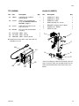
Remove the Electric Motor
1. Follow the Pressure Relief Procedure on page 15.
2. Loosen the clamp nut (DN) on the pump clamp
(DC), then remove the clamp.
3. Open the electric motor access door (DD).
4. Slide the electric motor away from the pump and
remove the electric motor (DA).
NOTE: Use the mounting bracket (MB) to hang the
electric motor in a secure location when not in use.
Never use the power cord to lift or adjust the pump.
Lifting or adjusting the pump with the power cord can
damage it and cause injury from electric shock.
AF
BC
K

Operation
3A8503G 17
Install the Electric Motor
1. Follow the Pressure Relief Procedure on page 15.
2. Disconnect power to the TPC.
3. If the pump has not been parked, pull the pump
lower rod up so that it can be coupled to the
electric motor.
NOTE: Parking the pump increases seal life on the
proportioner pump and increases the ease of
aligning the ProConnect features on the transfer
pump. The pump will automatically park at the
bottom of the stroke when the Reactor 3 is in Park
mode.
4. Open the electric motor access door (DD).
5. Align the notch of the electric motor coupler (CP)
with the button head (BH) of the pump lower.
6. Simultaneously slide the electric motor coupler (CP)
onto the button head of the pump lower and the
electric motor onto the pump lower. Close the
electric motor access door (DD).
7. Install the pump clamp (DC). Use a screwdriver or
rod to tighten the clamp nut (DN) 1/2 turn past
finger tight.
Using the Electric Motor
A new electric motor needs to be calibrated when
connected to a Transfer Pump Controller (or if the
connections are swapped at the TPC). To calibrate the
pump, see your Reactor 3 operation manual.
Upon each power-on cycle the electric motor will run
slowly for the first several strokes until the end stops
are established.
The TPC will proactively change pump direction in
order to minimize the number of times the pump needs
to switch direction when pumping. The pumps may not
necessarily change direction at the absolute top and
bottom of the stroke.
NOTE: Electric motors do not need pressure
transducers to operate, but can offer additional features
when used with a Reactor 3 system that has inlet
pressure transducers.
Controlling the Pump
The pressure and speed for this pump are controlled
through the Reactor proportioner. See your Reactor 3
operation manual for additional instructions.
Never use the power cord to lift or adjust the pump.
Lifting or adjusting the pump with the power cord can
damage it and cause injury from electric shock.
Switch off power and unplug the TPC. Wait five
minutes for power to dissipate before servicing.
DA
CP DD
BH
Always keep the electric motor access door (DD)
closed and secured with the clamp to prevent injury
from moving parts.

Operation
18 3A8503G
Daily Startup
1. Turn the TPC power switch (ZP) to ON.
2. Follow the Startup procedure in your Reactor 3
operation manual.
Daily Shutdown
1. Follow the Shutdown procedure in your Reactor 3
operation manual.
2. Turn the TPC power switch (ZP) to OFF.
NOTICE
Never allow the pump to run dry of the fluid being
pumped. A dry pump will quickly accelerate to a
high speed and could cause damage to the pump.
If the pump accelerates quickly or starts running
too fast, stop it immediately and check the fluid
supply. If the supply container is empty or air has
been pumped into the lines, refill the container and
prime the pump and the lines with fluid, or flush
and leave it filled with a compatible solvent. Be
sure to eliminate all air from the fluid system.
Do not attempt to operate unless it is securely
mounted in a drum.

Operation
3A8503G 19
Pump Status LEDs
The Transfer Pump Controller (TPC) uses five LEDs to communicate the current status of the pumps and TPC. The
two LEDs on the top relate to the electric motor status (A on the left, B in the center). The three LEDs on the bottom
right are the TPC status LEDs.
LED Status Definitions
LED Conditions Description
A/B Electric Motor Status LEDs
NOTE: The A/B electric motor
status LEDs may remain lit for up
to one minute after the power
switch (ZP) is turned off.
Off No AC Power Detected
Red and Blue Startup
Purple Idle
Blue On:
• 1 flash for top changeover
• 2 flashes for bottom changeover
Red Error
TPC Status Green Solid Low voltage power applied to module
Yellow Flashing Active communication
Red Steady Flashing Software update in progress
Red Random Flashing or
Solid
Module error exists
TPC Status
A/B Motor
Green
Yellow
Red
B Blue
A Blue

Troubleshooting
20 3A8503G
Troubleshooting
1. Follow Pressure Relief Procedure, page 15,
before checking or repairing pump.
2. Check all possible problems and causes before
disassembling pump.
NOTE: For additional troubleshooting information, go to
help.graco.com and search for E1 Transfer Pumps.
Maintenance
Monthly
Electrical connections can loosen over time due to
transporting equipment and normal operation.
Periodically check all electrical connections and tighten
as needed.
Daily
Check the clamp nut (DN) on a daily basis and tighten if
necessary.
Problem Cause Solution
The pump fails to operate Clogged fluid hose or valve Clear the hose or valves.
The pump operates, but the output is
low on both strokes
Clogged fluid hose or valve Clear the hose or valves.
Exhausted fluid supply Refill the fluid supply and reprime the
pump.
Worn or damaged valves or seals Service the valves or seals.
The pump operates, but the output is
low on the down stroke
Held open or worn intake valve Clear or service the valve.
Worn or damaged valves or seals Service the valves or seals.
The pump operates, but the output is
low on the upstroke
Held open or worn piston valve Clear or service the valve.
Worn or damaged valves or seals Service the valves or seals.
Erratic or accelerated operation Exhausted fluid supply Refill the fluid supply and reprime the
pump.
Pump slowly moves after fluid
shutoff in the down stroke
Clogged or dirty intake valve check
ball
Clean ball and seat.
Worn or damaged valves or seats Install repair kit.
Pump moves slowly after fluid
shutoff in the upstroke
Clogged or dirty piston ball or seat Clean ball and seat.
Worn or damaged valves or seats Install repair kit.
Page is loading ...
Page is loading ...
Page is loading ...
Page is loading ...
Page is loading ...
Page is loading ...
Page is loading ...
Page is loading ...
Page is loading ...
Page is loading ...
Page is loading ...
Page is loading ...
Page is loading ...
Page is loading ...
Page is loading ...
Page is loading ...
-
 1
1
-
 2
2
-
 3
3
-
 4
4
-
 5
5
-
 6
6
-
 7
7
-
 8
8
-
 9
9
-
 10
10
-
 11
11
-
 12
12
-
 13
13
-
 14
14
-
 15
15
-
 16
16
-
 17
17
-
 18
18
-
 19
19
-
 20
20
-
 21
21
-
 22
22
-
 23
23
-
 24
24
-
 25
25
-
 26
26
-
 27
27
-
 28
28
-
 29
29
-
 30
30
-
 31
31
-
 32
32
-
 33
33
-
 34
34
-
 35
35
-
 36
36


Graco 3A8503G, Core E1 Electric Transfer Pump Operating instructions
- Category
- Paint Sprayer
- Type
- Operating instructions
- This manual is also suitable for
Ask a question and I''ll find the answer in the document
Finding information in a document is now easier with AI
Related papers
-
Graco 308547G, Pressure Relief Valve Operating instructions
-
-
-
-
-
-
-
-
-
Graco H25 User manual
Other documents
-
 iPM IP02 Series Operating instructions
-
Fireye TD-00-8-500F-0-002-A - 129-199 WINC Connector Kit Technical Instructions
-
Titan Helix LP User manual
-
Graco Inc. 313872n User manual
-
-
-
-
-
 PMC PH-20 User manual
-
Alemlube 9968 Owner's manual

