Page is loading ...

Operation
PLURAL COMPONENT PROPORTIONER
®
A-2
5
Air operated, electrically heated, plural component proportioner
For spraying or dispensing 1:1 ratio polyurethane foam formulations and other 1:1 fast
setting materials.
Not for use in explosive atmospheres or hazardous locations.
This model is field-configurable to the following supply voltages:
230 V, 1 Phase
230 V, 3 Phase
380 V, 3 Phase
2000 psi (14 MPa, 138 bar) Maximum Fluid Working Pressure
80 psi (550 kPa, 5.5 bar) Maximum Air Working Pressure
See page 9 for model information, including maximum
working pressure and approvals.
Important Safety Instructions
Read all warnings and instructions in this
manual. Save these instructions.
ti16811a
3A1569B
EN

2 3A1569B
Contents
Proportioner Models . . . . . . . . . . . . . . . . . . . . . . . . 3
Systems . . . . . . . . . . . . . . . . . . . . . . . . . . . . . . . . . . 3
Related Manuals . . . . . . . . . . . . . . . . . . . . . . . . . . . 3
Warnings . . . . . . . . . . . . . . . . . . . . . . . . . . . . . . . . . 4
Important Two-Component Material Information . 7
Isocyanate Conditions . . . . . . . . . . . . . . . . . . . . . 7
Material Self-ignition . . . . . . . . . . . . . . . . . . . . . . 7
Keep Components A and B Separate . . . . . . . . . 7
Moisture Sensitivity of Isocyanates . . . . . . . . . . . 7
Foam Resins with 245 fa Blowing Agents . . . . . . 7
Changing Materials . . . . . . . . . . . . . . . . . . . . . . . 8
Typical Installation, without Circulation . . . . . . . . 9
Typical Installation, with Circulation . . . . . . . . . . 10
Component Identification . . . . . . . . . . . . . . . . . . . 11
Control Panel . . . . . . . . . . . . . . . . . . . . . . . . . . 13
Temperature Controls and Indicators . . . . . . . . 13
Setup . . . . . . . . . . . . . . . . . . . . . . . . . . . . . . . . . . . . 15
Locate Reactor A-25 . . . . . . . . . . . . . . . . . . . . . 15
Determine Power Source . . . . . . . . . . . . . . . . . 15
Electrical Requirements . . . . . . . . . . . . . . . . . . 15
Configure to Supply Power . . . . . . . . . . . . . . . . 16
Ground System . . . . . . . . . . . . . . . . . . . . . . . . . 18
Iso Pump Lubrication System Setup . . . . . . . . . 18
Fluid Supply Connections . . . . . . . . . . . . . . . . . 18
Air Supply Connection . . . . . . . . . . . . . . . . . . . 18
Recirculation / Pressure Relief Lines . . . . . . . . 19
Install Fluid Temperature Sensor (FTS) . . . . . . 19
Connect Heated Hose . . . . . . . . . . . . . . . . . . . . 19
Close Gun Fluid Inlet Valves A and B . . . . . . . . 20
Connect Whip Hose to Gun or Gun Fluid Manifold
20
Initial Startup . . . . . . . . . . . . . . . . . . . . . . . . . . . . . 21
Pressure Check Hose . . . . . . . . . . . . . . . . . . . . 21
Set Temperatures . . . . . . . . . . . . . . . . . . . . . . . 22
Supply Wet-Cups with Throat Seal Liquid . . . . . 23
Spraying . . . . . . . . . . . . . . . . . . . . . . . . . . . . . . . . . 24
Spray Adjustments . . . . . . . . . . . . . . . . . . . . . . 25
Park . . . . . . . . . . . . . . . . . . . . . . . . . . . . . . . . . . . . . 26
Pressure Relief Procedure . . . . . . . . . . . . . . . . . . 26
Shutdown . . . . . . . . . . . . . . . . . . . . . . . . . . . . . . . . 26
Flushing . . . . . . . . . . . . . . . . . . . . . . . . . . . . . . . . . 27
Operation . . . . . . . . . . . . . . . . . . . . . . . . . . . . . . . . 28
Daily Start-up Procedure . . . . . . . . . . . . . . . . . . 28
Fluid Circulation . . . . . . . . . . . . . . . . . . . . . . . . . . . 30
Circulation Through Reactor . . . . . . . . . . . . . . . 30
Circulation Through Gun Manifold . . . . . . . . . . . 31
DataTrak Controls and Indicators . . . . . . . . . . . . . 32
DataTrak Operation . . . . . . . . . . . . . . . . . . . . . . . . 33
Setup Mode . . . . . . . . . . . . . . . . . . . . . . . . . . . . 33
Run Mode . . . . . . . . . . . . . . . . . . . . . . . . . . . . . 33
Maintenance . . . . . . . . . . . . . . . . . . . . . . . . . . . . . . 34
Diagnostic Codes . . . . . . . . . . . . . . . . . . . . . . . . . . 35
Temperature Control Diagnostic Codes . . . . . . . 35
DataTrak Diagnostic Codes . . . . . . . . . . . . . . . . 35
Dimensions . . . . . . . . . . . . . . . . . . . . . . . . . . . . . . . 36
Technical Data . . . . . . . . . . . . . . . . . . . . . . . . . . . . 37
Graco Standard Warranty . . . . . . . . . . . . . . . . . . . 38

Proportioner Models
3A1569B 3
Proportioner Models
All proportioners can be configured to operate on 380V (4 wire), 230V (3 wire), or 230V 1Ø.
Systems
All systems include a proportioner, spray gun, and 60 ft (18.3 m) of heated hose.
Related Manuals
Manuals are available at www.graco.com.
Component manuals in English:
Part No.
Maximum Fluid Working
Pressure
psi (MPa, bar)
Maximum Air Working
Set Pressure
psi (kPa, bar)
Includes:
Approvals
DataTrak
(cycle count only)
Wheels
262572 2000 psi (14, 138) 80 psi (550, 5.5) --- ---
262614 2000 psi (14, 138) 80 psi (550, 5.5) 24A592
Part
Maximum Working
Pressure
psi (MPa, bar)
Proportioner
(see Typical
Installation,
without
Circulation)
Heated Hose Gun
50 ft (15 m) 10 ft (3 m) Model Part
P22614
2000 (14, 138)
262614
246678 246050
Probler P2 GCP2R1
AP2614
2000 (14, 138)
262614
246678 246050
Fusion
™
AP
246101
CS2614
2000 (14, 138)
262614
246678 246050
Fusion
™
CS
CS01RD
P22572
2000 (14, 138)
262572
246678 246050
Probler P2 GCP2R1
AP2572
2000 (14, 138)
262572
246678 246050
Fusion
™
AP
246101
CS2572
2000 (14, 138)
262572
246678 246050
Fusion
™
CS
CS01RD
Manual Description
3A1570
Reactor A-25 Proportioner, Repair-Parts
309577
Proportioning Pump, Repair-Parts
309815
Feed Pump Kit, Instructions-Parts
309827
Feed Pump Air Supply KIt, Instruc-
tions-Parts
309852
Circulation and Return Tube Kit, Instruc-
tions-Parts
309572
Heated Hose, Instructions-Parts
309550
Fusion
™
AP Spray Gun, Instructions-Parts
312666
Fusion
™
CS Spray Gun, Instructions-Parts
313213
Probler P2 Spray Gun, Instructions-Parts
313541
DataTrak Kits, Installation-Parts
312796
NXT
®
Air Motor, Instructions-Parts
Manual Description
3172585
Conforms to ANSI/U
L
Std. 499 Certified to
CAN/CSA Std.
C22.2 No. 88

Warnings
4 3A1569B
Warnings
The following warnings are for the setup, use, grounding, maintenance, and repair of this equipment. The exclama-
tion point symbol alerts you to a general warning and the hazard symbols refer to procedure-specific risks. When
these symbols appear in the body of this manual, refer back to these Warnings. Product-specific hazard symbols and
warnings not covered in this section may appear throughout the body of this manual where applicable.
WARNING
ELECTRIC SHOCK HAZARD
This equipment must be grounded. Improper grounding, setup, or usage of the system can cause electric
shock.
• Turn off and disconnect power at main switch before disconnecting any cables and before servicing or
installing equipment.
• Connect only to grounded power source.
• All electrical wiring must be done by a qualified electrician and comply with all local codes and
regulations.
TOXIC FLUID OR FUMES HAZARD
Toxic fluids or fumes can cause serious injury or death if splashed in the eyes or on skin, inhaled, or
swallowed.
• Read MSDSs to know the specific hazards of the fluids you are using.
• Store hazardous fluid in approved containers, and dispose of it according to applicable guidelines.
• Always wear chemically impermeable gloves when spraying, dispensing, or cleaning equipment.
PERSONAL PROTECTIVE EQUIPMENT
You must wear appropriate protective equipment when operating, servicing, or when in the operating area
of the equipment to help protect you from serious injury, including eye injury, hearing loss, inhalation of
toxic fumes, and burns. This equipment includes but is not limited to:
• Protective eyewear, and hearing protection.
• Respirators, protective clothing, and gloves as recommended by the fluid and solvent manufacturer.
BURN HAZARD
Equipment surfaces and fluid that’s heated can become very hot during operation. To avoid severe burns:
• Do not touch hot fluid or equipment.

Warnings
3A1569B 5
FIRE AND EXPLOSION HAZARD
Flammable fumes, such as solvent and paint fumes, in work area can ignite or explode. To help prevent
fire and explosion:
• Use equipment only in well ventilated area.
• Eliminate all ignition sources; such as pilot lights, cigarettes, portable electric lamps, and plastic drop
cloths (potential static arc).
• Keep work area free of debris, including solvent, rags and gasoline.
• Do not plug or unplug power cords, or turn power or light switches on or off when flammable fumes are
present.
• Ground all equipment in the work area. See Grounding instructions.
• Use only grounded hoses.
• Hold gun firmly to side of grounded pail when triggering into pail.
• If there is static sparking or you feel a shock, stop operation immediately. Do not use equipment until
you identify and correct the problem.
• Keep a working fire extinguisher in the work area.
SKIN INJECTION HAZARD
High-pressure fluid from gun, hose leaks, or ruptured components will pierce skin. This may look like just
a cut, but it is a serious injury that can result in amputation. Get immediate surgical treatment.
• Engage trigger lock when not spraying.
• Do not point gun at anyone or at any part of the body.
• Do not put your hand over the fluid outlet.
• Do not stop or deflect leaks with your hand, body, glove, or rag.
• Follow the Pressure Relief Procedure when you stop spraying and before cleaning, checking, or
servicing equipment.
• Tighten all fluid connections before operating the equipment.
• Check hoses and couplings daily. Replace worn or damaged parts immediately.
WARNING

Warnings
6 3A1569B
EQUIPMENT MISUSE HAZARD
Misuse can cause death or serious injury.
• Do not operate the unit when fatigued or under the influence of drugs or alcohol.
• Do not exceed the maximum working pressure or temperature rating of the lowest rated system
component. See Technical Data in all equipment manuals.
• Use fluids and solvents that are compatible with equipment wetted parts. See Technical Data in all
equipment manuals. Read fluid and solvent manufacturer’s warnings. For complete information about
your material, request MSDS from distributor or retailer.
• Do not leave the work area while equipment is energized or under pressure. Turn off all equipment and
follow the Pressure Relief Procedure when equipment is not in use.
• Check equipment daily. Repair or replace worn or damaged parts immediately with genuine
manufacturer’s replacement parts only.
• Do not alter or modify equipment.
• Use equipment only for its intended purpose. Call your distributor for information.
• Route hoses and cables away from traffic areas, sharp edges, moving parts, and hot surfaces.
• Do not kink or over bend hoses or use hoses to pull equipment.
• Keep children and animals away from work area.
• Comply with all applicable safety regulations.
PRESSURIZED ALUMINUM PARTS HAZARD
Use of fluids that are incompatible with aluminum in pressurized equipment can cause serious chemical
reaction and equipment rupture. Failure to follow this warning can result in death, serious injury, or
property damage.
• Do not use 1,1,1-trichloroethylene, methylene chloride, other halogenated hydrocarbon solvents or
fluids containing such solvents.
• Many other fluids may contain chemicals that can react with aluminum. Contact your material supplier
for compatibility.
THERMAL EXPANSION HAZARD
Fluids subjected to heat in confined spaces, including hoses, can create a rapid rise in pressure due to
the thermal expansion. Over-pressurization can result in equipment rupture and serious injury.
• Open a valve to relieve the fluid expansion during heating.
• Replace hoses proactively at regular intervals based on your operating conditions.
MOVING PARTS HAZARD
Moving parts can pinch, cut or amputate fingers and other body parts.
• Keep clear of moving parts.
• Do not operate equipment with protective guards or covers removed.
• Pressurized equipment can start without warning. Before checking, moving, or servicing equipment,
follow the Pressure Relief Procedure and disconnect all power sources.
WARNING

Important Two-Component Material Information
3A1569B 7
Important Two-Component Material Information
Isocyanate Conditions
Material Self-ignition
Keep Components A and B
Separate
Moisture Sensitivity of
Isocyanates
Isocyanates (ISO) are catalysts used in two component
foam and polyurea coatings. ISO will react with moisture
(such as humidity) to form small, hard, abrasive crystals,
which become suspended in the fluid. Eventually a film
will form on the surface and the ISO will begin to gel,
increasing in viscosity. If used, this partially cured ISO
will reduce performance and the life of all wetted parts.
NOTE: The amount of film formation and rate of crystal-
lization varies depending on the blend of ISO, the
humidity, and the temperature.
To prevent exposing ISO to moisture:
• Always use a sealed container with a desiccant
dryer in the vent, or a nitrogen atmosphere. Never
store ISO in an open container.
• Keep the ISO lube pump reservoir (if installed) filled
with Graco Throat Seal Liquid (TSL), Part 206995.
The lubricant creates a barrier between the ISO and
the atmosphere.
• Use moisture-proof hoses specifically designed for
ISO, such as those supplied with your system.
• Never use reclaimed solvents, which may contain
moisture. Always keep solvent containers closed
when not in use.
• Always lubricate threaded parts with ISO pump oil
or grease when reassembling.
Foam Resins with 245 fa
Blowing Agents
Some foam blowing agents will froth at temperatures
above 90°F (33°C) when not under pressure, especially
if agitated. To reduce frothing, minimize preheating in a
circulation system.
Spraying or dispensing materials containing
isocyanates creates potentially harmful mists, vapors,
and atomized particulates.
Read material manufacturer’s warnings and material
MSDS to know specific hazards and precautions
related to isocyanates.
Prevent inhalation of isocyanate mists, vapors, and
atomized particulates by providing sufficient
ventilation in the work area. If sufficient ventilation is
not available, a supplied-air respirator is required for
everyone in the work area.
To prevent contact with isocyanates, appropriate
personal protective equipment, including chemically
impermeable gloves, boots, aprons, and goggles, is
also required for everyone in the work area.
Some materials may become self-igniting if applied
too thickly. Read material manufacturer’s warnings
and material MSDS.
Cross-contamination can result in cured material in
fluid lines which could cause serious injury or
damage equipment. To prevent cross-contamination
of the equipment’s wetted parts, never interchange
component A (isocyanate) and component B (resin)
parts.

Important Two-Component Material Information
8 3A1569B
Changing Materials
Changing the material types used in your equipment
requires special attention to avoid equipment damage
and downtime.
• When changing materials, flush the equipment mul-
tiple times to ensure it is thoroughly clean.
• Always clean the fluid inlet strainers after flushing.
• Check with your material manufacturer for chemical
compatibility.
• When changing between epoxies and urethanes or
polyureas, disassemble and clean all fluid compo-
nents and change hoses. Epoxies often have
amines on the B (hardener) side. Polyureas often
have amines on the B (resin) side.

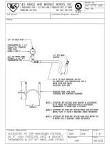
Typical Installation, without Circulation
3A1569B 9
Typical Installation, without Circulation
Key for FIG. 1
A Reactor Proportioner
BHeated Hose
C Fluid Temperature Sensor (FTS)
D Heated Whip Hose
ESpray Gun
F Proportioner and Gun Air Supply Hose
G Feed Pump Air Supply Lines
H Waste Containers
J Fluid Supply Lines
K Feed Pumps
L Agitator (if required)
M Desiccant Dryer
N Bleed Lines/Over Pressure Relief
P Gun Fluid Manifold
FIG. 1: Typical Installation, without Circulation
A
B
C*
D
E
K
L
M
F
P
H
* Shown exposed for clarity. Wrap with tape during operation.
K
H
J
G
ti16812a
J
N
N

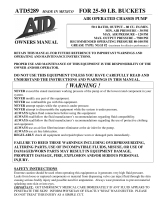
Typical Installation, with Circulation
10 3A1569B
Typical Installation, with Circulation
Key for FIG. 2
A Reactor Proportioner
B Heated Hose
C Fluid Temperature Sensor (FTS)
D Heated Whip Hose
ESpray Gun
F Proportioner and Gun Air Supply Hose
G Feed Pump Air Supply Lines
J Fluid Supply Lines
K Feed Pumps
L Agitator (if required)
M Desiccant Dryer
N Recirculation/Over Pressure Relief Return Hoses
P Gun Fluid Manifold
FIG. 2: Typical Installation, with Circulation
A
B
C*
D
E
K
L
M
F
N
P
* Shown exposed for clarity. Wrap with tape during operation.
J
N
K
M
G
ti16813a
J
N
F

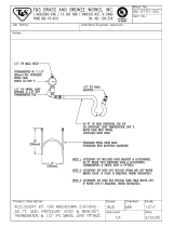
Component Identification
3A1569B 11
Component Identification
FIG. 3: Typical Installation
AG
T
W
Z
AF
R
AA
S
U
V
AE
AC
Y
X
ti16814a
AI
DD
GG
FF
AD
AB
AH

Component Identification
12 3A1569B
Key:
R Main Disconnect Switch - Controls power to
heating circuits. I
S Main Air Filter - Filters system air supply.
T Resin (B) Pressure Gauge - Displays pressure in
resin proportioning system (B side).
U Resin (B) - Inlet Supply Valve
V Resin (B) Fluid Y-Strainer - (20 mesh)
W ISO (A) Pressure Gauge - Displays pressure in
isocyanate proportioning system (A side).
XISO (A) - Inlet Supply Valve
Y ISO (A) Fluid Y-Strainer - (20 mesh)
Z ISO (A) Pump Lube System - Behind Proportioner
shroud. (A side only)
AA ISO (A) - Packing Nut and Lube Cup - (A side
only)
AB *Primary Heater Thermocouples - Senses
temperature of primary heater and inputs that
information.
AC FTS Jumper Harness - Carries electrical signal
from FTS sensor in isocyanate hose to hose
temperature controller.
AD Primary Heaters - Heats material to required
dispensing temperature.
AE ISO (A) - (Isocyanate) Proportioning Pump -
Draws in and dispenses a fixed volume of
isocyanate to gun.
AF Resin (B) Proportioning Pump - Draws in and
dispenses a fixed volume of resin to gun.
AG Power-Lock
™
Hose Heat Connection - Connects
power to heated hoses.
AH *Primary Heater Over-Temperature Switches -
Sends signal to temperature controller if heater
exceeds maximum temperature condition.
AI Resin (B) Pump Wet Cup - Access for daily wet
cup refill.
DD Main Air Inlet Ball Valve - (1/2 NPT female fitting)
FF ISO (A) Inlet - Fitting (3/4 swivel fitting)
GG Resin (B) Inlet - Fitting (3/4 swivel fitting)

Component Identification
3A1569B 13
Control Panel
Temperature Controls and Indicators
ELECTRONIC MONITORING SYSTEM
°
F
°
C
A
B
Air Motor
Pressure Gauge
Air Pressure
Regulator
Air Motor
Shutoff Valve
DataTrak (optional)
See page 32.
See Tempera-
ture Controls
and Indicators
ti16815a
NOTICE
To prevent damage to the softkey buttons, do not press
the buttons with sharp objects such as pens, plastic
cards, or fingernails.
°
F
°
C
A
B
Zone A Arrow Keys
Zone B Arrow Keys
Hose Zone Arrow Keys
Temperature Scale Keys
Heater A On/Off Key
Heater Power Indicators
Target Temperature Key
Actual Temperature Key
Temperature Displays
Hose Heater On/Off Key
Heater B On/Off Key

Component Identification
14 3A1569B
Main Power Switch
Located on right side of unit, page 11. Turns heater
power ON and OFF . Does not turn
heater zones or pumps on.
Actual Temperature Key/LED
Press to display actual temperature.
Press and hold to display electrical current.
Target Temperature Key/LED
Press to display target temperature.
Press and hold to display heater control circuit
board temperature.
Temperature Scale Keys/LEDs
Press or to change temperature scale.
Heater Zone On/Off Keys/LEDs
Press to turn heater zones on and off. Also clears
heater zone diagnostic codes, see page 35.
NOTE: LEDs flash when heater zones are on. The dura-
tion of each flash shows the extent that the heater is
turned on.
Temperature Arrow Keys
Press , then press or to adjust tem-
perature settings in 1 degree increments.
Temperature Displays
Show actual temperature or target temperature of
heater zones, depending on selected mode. Defaults to
actual at startup. Range is 32-190°F (0-88°C) for A and
B, 32-180°F (0-82°C) for hose.
Circuit Breakers
Located inside Reactor cabinet.
°
F
°
C
Ref. Size Component
CB1 50 A Hose Secondary (single)
CB2 30 A Hose Primary (double)
CB3 25 A Heater A (double)
CB4 25 A Heater B (double)
CB1
CB2
CB3
CB4
ti17569a

Setup
3A1569B 15
Setup
Locate Reactor A-25
1. Locate Reactor A-25 on a level surface and bolt in
place to the floor with 3/8 in. (10 mm) bolts, unless
the Reactor needs to remain portable.
• Two bolts through the 2 in. (50 mm) deep caster
bushings in the rear.
• Two bolts through the 3-5/8 in. (168 mm) deep
caster bushings in the front.
2. Do not expose Reactor A-25 to rain.
3. If you need to move the machine, add
optional wheel kit.
4. Lift with hoist only from bar spanning across top of
cart.
Determine Power Source
Reactor A-25 can be wired to 3 types of power source:
• 230 Volt / 1 Phase
• 230 Volt / 3 Phase Delta (3 wire + ground PE)
• 380 Volt / 3 Phase WYE (4 wire + ground PE)
(220 Volts to Neutral)
Electrical Requirements
NOTE: Power cord is not supplied.
Improper wiring may cause electric shock or other
serious injury if work is not performed properly.
• Have a qualified electrician connect power and
ground to main power switch terminals and
ground lug.
• Ensure your installation complies with all National,
State, and Local safety and fire codes.
• Ensure that incoming power is disconnected and
locked out at the source.

Setup
16 3A1569B
Configure to Supply Power
NOTE: Both cord connection AND jumper positioning
steps on page 17 must be completed.
Step One - Connect Electrical Cord
NOTE: Disregard terminal numbers on disconnect
switch blocks. Wire to positions shown. Terminals will
accept up to #8 AWG (10 mm
2
) conductors.
1. Using a flat screw driver, turn cover fasteners 90°
counterclockwise. Lift and pull the front cover away.
2. Connect main power cord to electrical console as
follows:
a. Feed power cord through strain relief (SR) on
right side of unit. Push black die release lever
(RL) down to release contacts block (PD) for
easy wiring.
NOTE: Strain relief accepts cords 0.59 to 1.0 in. (15-25
mm) diameter.
b. Connect power leads to Power Disconnect
Switch (PD). Snap contacts block (PD) back
onto switch.
c. Tighten strain relief nut.
d. Connect ground wire to ground lug (GL).
3. Replace lower front shroud. Reinstall the two
screws retained in Step 1.
230V, 1 Phase: Use a screwdriver to connect two power
leads to the top two middle terminal positions as shown.
Connect green to ground (GND). See page 17 for proper
jumper positions.
NOTE: Disregard terminal numbers on disconnect
switch blocks. Wire to positions shown.
230V, 3 Phase Delta: Use a screwdriver to connect
three power leads to top three left terminals as shown.
Connect green to ground (GND). See page 17 for
proper jumper positions.
380V, 3 Phase WYE: Use a screwdriver to connect four
power leads to the top terminals as shown. Connect
neutral only to N. Connect green to ground (GND). See
page 17 for proper jumper positions.
SR
PD
GL
RL
ti17570a

Setup
3A1569B 17
Step Two - Install Power Jumpers
Find location for power jumpers which are in a plastic
bag tie wrapped to the ground lug.
1. Turn screws counter-clockwise on the upper part of
the shroud until they stop. Pull door up and out.
2. Install red jumpers from the storage bag to the
positions shown for your power.
• Push the jumper firmly into the new position.
• If necessary, a flat-blade screwdriver can be
used under the ridge on the side of the jumper
to remove them.
3. Replace front shroud.
Step Three - Reposition Heater Jumpers
(if necessary)
Find location of Heater Jumpers.
Machines are shipped with heaters wired for 6000 watts.
To reposition heater jumpers for 3000 watts, change
jumper positions as shown below.
1. Turn screws counter-clockwise on the upper part of
the shroud and remove by pulling them out.
2. Move red jumpers from the storage positions to the
positions shown for your power.
• A flat-blade screwdriver can be used under the
ridge on the side of the jumper to remove them.
• Push the jumper firmly into the new position.
3. Replace lower front shroud.
Power Jumper Location
Heater Jumper Location
NEW
ti17569a
Heater Jumpers
Install Power Jumpers
230V 1ø 230V 3ø Delta 380V 3ø WYE
Step Two
TB2
Terminal Blocks
Install red jumpers
Step Three
TB2
Terminal Blocks
Position red jumpers
3000 WATTS6000 WATTS

Setup
18 3A1569B
Ground System
• Reactor: is grounded through power cord; see page
16.
• Spray gun: connect whip hose ground wire to FTS;
see page 19. Do not disconnect wire or spray with-
out whip hose.
• Fluid supply containers: follow your local code.
• Object being sprayed: follow your local code.
• Solvent pails used when flushing: follow your local
code. Use only metal pails that are conductive.
Place them on a grounded surface. Do no place pail
on a nonconductive surface, such as paper or
cardboard, which interrupts grounding continuity.
• To maintain grounding continuity when flushing or
relieving pressure, hold a metal part of spray gun
firmly to the side of a grounded metal pail, then
trigger gun.
Iso Pump Lubrication System
Setup
Prepare isocyanate pump lubrication system as follows:
1. Lift lubricant reservoir out of bracket and remove
reservoir from cap.
2. Fill reservoir 3/4 full with TSL.
3. Thread reservoir onto cap assembly and place it
into bracket.
The lubrication system is now ready for operation; no
priming is required.
Fluid Supply Connections
Feed pumps are typically used. Siphon feeding is not
recommended. Connect material supply to inlets of
proportioning unit as follows:
1. Connect fluid inlet ball valves (U.X) and y-strainers
(V, Y) to pump inlets.
2. Ensure the A- and B- inlet ball valves (U,X) on pro-
portioning unit are closed.
3. Connect and tighten B- supply hose (J) to 3/4 NPT
swivel fitting (GG) on B- inlet ball valve (U), and to
resin transfer pump.
4. Connect and tighten A- supply hose (BB) to 1/2 NPT
swivel fitting (FF) on A- inlet ball valve (X), and to
isocyanate transfer pump. See F
IG. 3, page 11.
Air Supply Connection
Connect main air supply (F) to air inlet 1/2 in. npt (f)
valve (DD) at air filter (S). Hose fitting requires a 1/2
NPT male fitting.
NOTE: Use a minimum of 3/8 in. ID air line (not sup-
plied) to deliver air supply to proportioning unit. Use 1/2
in. ID hose if over 15 ft long.The main air supply must be
clean and free of oil and contaminants.
The equipment must be grounded to reduce the risk
of static sparking and electric shock. Electric or static
sparking can cause fumes to ignite or explode.
Improper grounding can cause electric shock.
Grounding provides an escape wire for the electric
current.
U
J
GG
V
ti17571a
F
S
DD
ti17572a

Setup
3A1569B 19
Recirculation / Pressure Relief
Lines
If Recirculating to Supply Drum: Connect high
pressure hose (R) to relief fittings (BA, BB) of both
PRESSURE RELIEF/SPRAY valves. Route hose back
to component A and B drums. Refer to manual 309852.
Alternate recirculation hoses (requires adapter
fittings):
249508 - ISO (A) (moisture guard) red hose, 1/4 in. (6
mm) ID; #5 JIC fittings (m x f); 35 ft (10.7 m) long.
249509 - Resin (B) blue hose; 1/4 in. (6 mm) ID, #6 JIC
fittings (m x f), 35 ft (10.7 m) long.
Install Fluid Temperature Sensor
(FTS)
Install FTS between main hose and whip hose. See
Heated Hose manual for instructions.
Connect Heated Hose
NOTE: See heated hose manual for detailed instruc-
tions for Graco heated hoses.
1. Turn main power OFF.
2. Assemble heated hose sections, FTS, and whip
hose. See Heated Hose manual for instructions.
3. Connect A and B hoses to A and B outlets on
Reactor fluid manifold (FM). Hoses are color coded:
red for component A (ISO), blue for component B
(RES). Fittings are sized to prevent connection
errors.
NOTE: Manifold hose fittings (VV, WW) allow use of 1/4
in. and 3/8 in. ID Reactor heated fluid hoses.
4. Connect heated hose air line (AH) to proportioner
air hose.
Do not install shutoffs downstream of the
PRESSURE RELIEF/SPRAY valve outlets (BA, BB).
The valves function as over pressure relief valves
when set to SPRAY. Lines must be open so valves
can automatically relieve pressure when machine is
operating.
If circulating fluid back to the supply drums, use high
pressure hose rated to withstand the maximum
working pressure of this equipment.
BB
BA
ti8441a
R
R
NOTICE
The fluid temperature sensor (FTS) and whip hose
must be used with heated hose; see page 19. Hose
length, including whip hose, must be 60 ft (18.3 m) min-
imum.
FM
VV
WW
ti17788a
AH
PH

Setup
20 3A1569B
5. Connect cables (SS). Connect electrical connectors
(NN). Be sure cables have slack when hose bends.
Wrap cable and electrical connections with electrical
tape.
Close Gun Fluid Inlet Valves A
and B
Connect Whip Hose to Gun or
Gun Fluid Manifold
For Probler P2 guns: Connect hoses to inlet valves.
For Fusion guns: Connect hoses to inlet manifold. Do
not connect manifold to gun.
1. Overlap A and B component hoses and assemble to
gun or gun manifold fittings as shown.
2. Tighten fittings to A and B component hoses.
Ensure hose remains flat after fittings are tightened.
Loosen and retighten fittings as necessary to elimi-
nate any torque on hoses.
ti17787a
SS
NN
ti2411a
Fusion AP Gun shown.
ti12158a
Fusion AP Gun shown.
/