Page is loading ...


2
English
Introduction
Dear customer,
we are pleased that you have decided to use our product and thank you for your trust! You made a
good choice.
This motion detector (hereinafter referred to as "device") has been developed and manufactured with
the greatest care. Please read these operating instructions completely and observe all operating and
safety instructions, as this will ensure the best possible handling of the device. This document is
regarded as assembly and maintenance instructions.
ABUS Security-Center hereby declares that the enclosed product complies with the following
guidelines concerning the product:
RED Directive 2014/53/EU, EMC Directive 2014/30/EU, Low Voltage Directive 2014/35/EU, RoHS
Directive 2011/65/EU. The full text of the EU Declaration of Conformity is available at the following
Internet address www.abus.com/product/PLBW10000
It can also be obtained from the following address:
ABUS Security Center GmbH & Co KG,
Left Kreuthweg 5, 86444 Affing, GERMANY
If you have any questions or suggestions, please contact our customer service:
Mail: ABUS Support, Linker Kreuthweg 5, 86444 Affing, Germany
E-mail: support@abus-sc.com
Phone: +49 8207 959 90 0
Opening hours hotline: Mon-Thu: 08 - 17 h; Fri: 08 - 14 h
All contained company names and product names are trademarks of their respective owners. All rights
reserved.
Disclaimer
This operating manual has been prepared with the utmost care. Should you nevertheless notice any
omissions or inaccuracies, please notify us in writing at the above address.
Your rights are limited to the repair or replacement of this product in the condition as delivered. ABUS
Security Center assumes no liability for any special, incidental or consequential damages, including
but not limited to loss of revenue, loss of profits, restrictions in the use of the software, loss or recovery
of data, costs for replacement equipment, downtime, property damage and claims by third parties, as
a result of, among other things, the followinga. the contractual, statutory or damage compensation
claims arising from the warranty, irrespective of other limited warranty provisions or those implied by
law, or in the event that the limited warranty does not apply, the scope of liability of ABUS Security
Center is limited to the purchase price of the product.
The contents of this manual may be changed without prior notice.
© ABUS Security-Center GmbH & Co KG, 09/2019

3
English
Important Safety Instructions
Appropriate use
Use the device exclusively for the purpose for which it was built and designed! Any other use is
considered as not intended!
Damage caused by disregarding these safety instructions invalidates the warranty. We assume
no liability for consequential damages!
Unpacking
While unpacking the device, handle it with extreme care. Packaging and packaging aids are recyclable
and should always be sent for recycling.
If the original packaging is damaged, first check the device. If the device is damaged, return it
with the packaging and inform the delivery service.
Please ensure that the packaging contains the DSK (Device Specific Key) card.
This card shows the DSK of your ABUS Z-Wave device. Please keep them in a safe
place. Every S2 (Security 2) certified Z-Wave controller requires the DSK to include
the product in the Z-Wave network.
Installation site Operating environment
Do not place any heavy objects on the unit. The device is only designed for operation in rooms with
appropriate temperature or humidity (e.g. bathrooms) or excessive dust. For an exact specification
check the technical data of the individual devices. Ensure that there is always adequate ventilation, no
direct heat sources are applied to the device, no direct sunlight or strong artificial light is applied to
indoor equipment, the device is not in the immediate vicinity of magnetic fields (e.g. loudspeakers), no
open fire sources (e.g. Burning candles) on or next to the unit, contact with splashing and dripping water
on indoor units and aggressive liquids is avoided, the unit is not operated near water, in particular, the
unit must never be submerged (do not place objects filled with liquids, e.g. vases or drinks on or next
to the unit), no foreign objects may enter the unit, the unit is not exposed to strong temperature
fluctuations, as otherwise air humidity may condense and lead to electrical short circuits, the unit is not
exposed to excessive shocks and vibrations.
Children
Do not allow electrical devices to get into the hands of children! Never allow children to use electrical
equipment unsupervised. Children are not always able to recognize possible dangers correctly. Small
parts can be fatal if swallowed. Also keep the packaging film away from children. There is danger of
suffocation! This device should not be handled by children. Springy parts can jump out if used
improperly and cause injuries (e.g. eyes) to children.

4
English
Notes on handling batteries
Make sure that batteries are not in the hands of children. Children could put batteries in their
mouths and swallow them. This can lead to serious damage to health. In this case consult a
doctor immediately!
Normal batteries must not be charged, heated or thrown into an open fire (danger of explosion!)
Do not expose the battery to any heat source or direct sunlight and do not store it in a place with
a very high temperature.
The battery must not come into contact with water.
The battery must not be disassembled, punctured or damaged.
The battery contacts must not be short-circuited.
Replace weakening batteries in good time.
Always replace all batteries at the same time and use batteries of the same type. Ideally you
should use identical batteries from the same manufacturer as those from the original scope of
delivery, as the device has been intensively tested with these batteries and thus optimum
function is ensured.
Leaking or damaged batteries can cause burns on contact with skin. Use suitable protective
gloves in this case. Clean the battery compartment with a dry cloth.
Cleaning
Dusty equipment must be cleaned. Dust deposits in the air slots can be sucked off or blown out.
If necessary, the dust can be removed with a brush.
The surface can be cleaned with a cloth slightly moistened with soapy water. Only use suitable
microfibre cloths for high-gloss surfaces.
Make sure that no water gets inside the device!
Do not clean the appliance in the dishwasher!
Do not use sharp, pointed, abrasive, corrosive cleaning agents or hard brushes!
Do not use chemicals!
Do not clean the device with easily flammable liquids!
Notes on the disposal of the device
Attention: The EU Directive 2012/19/EU regulates the proper return, treatment and
recycling of used electronic equipment. This symbol means that, in the interest of
environmental protection, the device must be disposed of at the end of its service life in
accordance with the applicable legal regulations and separately from household and
commercial waste. The old device can be disposed of at the appropriate official
collection points in your country. Follow local regulations when disposing of the
materials. For further details about the withdrawal (also for non-EU countries), please
contact your local administration. Separate collection and recycling conserves natural resources and
ensures that all regulations for the protection of health and the environment are observed when
recycling the product.

5
English
Table of contents
1. Product ............................................................................................................................................. 6
1.1. Scope of delivery ..................................................................................................................... 6
1.2. Device features ........................................................................................................................ 6
1.3. Operating principle .................................................................................................................. 7
1.4. Performance features .............................................................................................................. 7
1.5. Use in systems of different manufacturers .............................................................................. 7
1.6. DSK code ................................................................................................................................. 7
2. Functional overview .......................................................................................................................... 8
2.1. Inclusion / teach-in device ....................................................................................................... 8
2.2. Planning, mounting and installation ......................................................................................... 9
2.3. Exclusion / teach-out device .................................................................................................. 11
2.4. Reset factory settings ............................................................................................................ 12
2.5. Waking up the device / Wake-up ........................................................................................... 12
2.6. Behavior PIR sensor .............................................................................................................. 13
3. Advanced Z-Wave Parameters ...................................................................................................... 14
3.1. Association Groups ............................................................................................................... 14
3.2. WakeUp Time ........................................................................................................................ 14
3.3. Reports .................................................................................................................................. 15
3.4. Overview configuration parameters ....................................................................................... 16
3.5. Supported command classes ................................................................................................ 17
3.6. Supported security levels ...................................................................................................... 17
4. Technical data ................................................................................................................................ 18

6
English
1. Product
1.1. Scope of delivery
Nexello Dual Motion Detector
1x GP CR123 battery
Mounting material: screws, dowels
Quick guide & safety instructions
DSK card
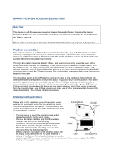
1.2. Device features
No Designation Comment
A Front cover Connected to the rear part with a screw at the bottom
B Upper Fresnel Lens For motion detection
C Lower Fresnel Lens For motion detection
D Tamper contact Triggers Tamper alarm
E Link Button Manual triggering of the wake-up command, inclusion, exclusion and
reset
F Battery compartment Observe polarity
G LED indicator Status display for various processes
(Inclusion, exclusion, reset,
error)
H Hygrometer Opening for temperature and humidity measurement
I Screw Housing Screw
J Bracket For wall mounting: flat wall or corner mounting.
Z-Wave QR Code DSK Sticker for S2 Inclusion is located on the
backside of the bracket
H, I
J

7
English
1.3. Operating principle
The device was developed for use in alarm and home automation systems that use the Z-Wave wireless
standard. The device has the following functions:
Motion detector
It uses Passive Infrared (PIR) technology to detect movement in a defined area by detecting the
changes in thermal radiation caused by the moving body inside or outside the detection zone.
With the dual PIR sensor (dual-lens technology), the sensor hides pets up to approx. 38kg, so
that your pet can move freely without triggering the sensor.
When the motion detector is triggered, an alarm signal is sent to the Z-Wave controller. The
indicator LED lights up when motion is detected.
Integrated temperature and humidity sensor
At periodic intervals, the unit automatically sends the measured temperature and humidity value
to the Z-Wave controller or on request of the Z-Wave controller.
Tamper protection between the device and wall bracket
When the housing is opened, the tamper switch is triggered and the device sends a tamper
alarm to the Z-Wave controller. The tamper contact must remain pressed for three seconds to
reset the tamper alarm.
1.4. Performance features
The device..:
...is a battery-powered motion detector
...is due to its design only suitable for wall mounting
...is Z-Wave Plus compatible & certified
...supports the Z-Wave S2 standard (Security 2)
...has a low-battery warning function
...was developed for indoor installation
1.5. Use in systems of different manufacturers
Communication is via the Z-Wave EU frequency (868.4 Mhz). You can integrate the device into any Z-
Wave network with a certified Z-Wave controller, regardless of manufacturer. All non-battery powered
nodes in the network act as amplifiers to amplify the wireless communication of the network.
1.6. DSK code
The DSK code (Device-Specific Key) is the device-specific key of your device and is required for secure
teach-in (inclusion) via S2 on the Z-Wave controller. The first 5 digits of the DSK code can be found on
the QR Code sticker on the backside of the bracket of the product. Please enter them in the inclusion
process when prompted. Alternatively, you can transfer the entire DSK code that you find on the
enclosed DSK card to the Z-Wave controller via QR Code Scan. Please keep the DSK card in a safe
place!
Hint:
We recommend the secure S2 inclusion (must be supported by the Z-Wave controller) When prompted,
please enter the 5 digits of the DSK code (bottom of the device) or the complete DSK code (QR code).

8
English
2. Functional overview
2.1. Inclusion / teach-in device
Open the screw and remove the front cover of the
motion sensor.
Activate the inclusion mode (teach-in mode) on the Z-
Wave controller. (please refer to the Z-Wave controller
manual for more details)
Press the "+" button (Add / Inclusion) in your Z-Wave
app and follow the instructions to set the Z-Wave
controller to inclusion mode.
Keep the device within reach of the Z-Wave controller.
Remove the safety strip from the battery compartment.
We recommend the exclusive use of the original GP
battery from the scope of delivery.
The device supports automatic inclusion, i.e. it
automatically goes into inclusion mode when it is
powered and not yet connected to a Z-Wave controller.
The LED starts flashing.
Alternative/manual inclusion:
If you have already inserted the batteries, press the
Link button 3 times quickly (within 1.5 seconds) to start
the inclusion process.
Successful inclusion is displayed in the app or on the
Z-Wave controller and the status LED on the device
stops flashing.
It may take up to 60 seconds after inclusion before
the LED goes out. During this time the PIR sensor
calibrates itself, only as soon as this warm-up phase
is completed the LED goes out.
Repeat the inclusion process if it was not successful.
If a new attempt fails as well, first carry out a factory
reset on the device, see 2.5.

9
English
2.2. Planning, mounting and installation
The device uses low-power radio signals to communicate with the Z-Wave controller. To achieve the
best results, please note the following:
Please do not attach directly to metal planes or metal constructions, as this may limit the range.
The device has a radio range of up to 40 m.
The battery life of the device is reduced if the wireless connection to the Z-Wave controller is not
direct but via a repeater.
Test mode
Press the tamper switch 3 times in 1.5 seconds to activate the test mode. The test mode switches off
automatically after 10 minutes.
In test mode
the preset waiting time is ignored and several movement messages are also sent one after the
other without a reset.
Every 5 seconds a check is made to see if there is any movement. Accordingly, the LED lights
up when motion is present and a motion message is sent. If there is no movement, the reset
message is sent.
Use the test mode to select the optimal installation location.
Select installation location
The detector is only suitable for indoor installation.
When selecting a position for the detector, the following points should be observed:
Do not install the detector opposite a window or where it is exposed to direct sunlight. PIR
detectors are not suitable for use in conservatories due to the high temperature fluctuations.
Do not install the detector where it is exposed to fans or air conditioners.
Do not install the detector near a heat source (e.g. fire, radiator, boiler, etc.).
Do not mount the detector in a position where it is subject to excessive vibration.
Mounting instructions:
The detector is designed for mounting on a flat wall or
in a corner.
If possible, mount the detector in the corner of the
room so that the path of a person passes through the
detection zone. PIR detectors respond more
effectively to movement through the detection zone
than to movement towards the sensor.
Sensitive
Insensitive

10
English
Mount the PIR detector in one of 2 m. At this height,
the detection range of the detector is optimised, i.e. 12
metres range and 90° detection angle.
The PIR detector ignores pets up to a height of approx.
60 cm in this installation.
Mount the PIR detector slightly higher if the detector is
still triggered by the pet.
Do not mount the detector too high, otherwise it will
not be triggered by humans.
Use the bracket as a template to mark the position of
two drill holes on the wall. There are two markings
each for wall or corner mounting.
Fix the bracket to the wall using the supplied plugs and
screws.
Do not overtighten the screws to avoid damaging the
bracket.
Place the base on the bracket and then press the unit
against the wall.
Connect the two parts again with the metric screw.

11
English
2.3. Exclusion / teach-out device
Activate the exclusion mode (teach-out mode) on the
Z-Wave controller. (please refer to the Z-Wave
controller manual for more details)
Press the "-" button (Remove / Exclusion) in your Z-
Wave app and follow the instructions to set the Z-Wave
controller to Exclusion mode.
Press the Link button 3 times quickly (within 1.5
seconds) to start the exclusion on the device.
The successful exclusion is displayed in the app or on
the Z-Wave controller

12
English
2.4. Reset factory settings
Press the Link button 3 times quickly (within 1.5
seconds).
Press quickly (within 1 second)
a fourth time and press and hold the Link button for at
least 5 seconds.
The device is now reset to factory settings.
Hint:
This procedure should only be used if the primary
network controller is not capable of acting.
If the device is set to factory default, the status is set
to "not included" and the association settings and
possible configurations are reset to default.
2.5. Waking up the device / Wake-up
Press the Link button once to wake up the device. It
then establishes a connection to the Z-Wave controller
and transmits the current status.

13
English
2.6. Behavior PIR sensor
Warm up phase
It takes about 1 minute for the PIR sensors to warm up after the battery is inserted. During this time the
LED behind the lens will light up. When the LED goes out, it means that the warm-up process is
complete and the detector is ready for detection.
Hint:
This has no effect on the inclusion/exclusion process.
After removing the batteries, wait 5 seconds before inserting them again.
PIR waiting time
As soon as motion is detected, the device's LED lights up and it sends a motion alarm to the Z-
Wave controller. The device now waits for a preset time (waiting time) until it resets the motion
alarm to the Z-Wave controller.
If motion is still present after 160 seconds, a new motion alarm is sent and the waiting time for
resetting the motion alarm is reset. The detector will not reset the motion alarm until the waiting
time for reset has expired without motion detection.
The default period of the reset waiting time is 180 seconds. Changes have a significant effect
on the expected battery life.

14
English
3. Advanced Z-Wave Parameters
3.1. Association Groups
Z-Wave devices can control other devices directly. This direct control is called association in Z-Wave.
For this purpose, the device ID of the device to be controlled must be stored in the controlling devices.
This takes place in so-called association groups. An association group is always linked to an event in
the controlling device (keystroke or triggering of a sensor). When this event occurs, a control command
- usually a BASIC SET - is sent to all devices stored in an association group.
The device supports two association groups:
Group-
Number Maximum
Devices Group name Profile Command class
Group 1 1 Lifeline General
Notification report
Battery report
Device Reset Locally Notification
Sensor Multilevel Report
Group 2 4 PIR control Notification Basic set
Group 1 (Association Z-Wave Controller)
The Lifeline Association is automatically established between the Z-Wave controller and the
device during inclusion and defines what information is exchanged between the Z-Wave
controller and the device.
Group 2 (direct association to terminals)
When the motion alarm is triggered, it sends a BASIC SET On / Off command to the nodes of
group 2
3.2. WakeUp Time
The time between the WakeUp Notification Commands can be set in the Wakeup Command Class
within the following values:
Description Value
Minimum wake-up interval 600s
Maximum wake-up interval 86400s (1 day)
Default value Wake-up interval 21600s (6 hours)
Interval steps 600s

15
English
3.3. Reports
Notification report
Event Type Attribute Parameter Length Event Parameters
Power is applied for the first time 0x08 0x01 0x00
Motion alarm 0x07 0x08 0x00
Motion alarm reset (no Event) 0x07 0x00 0x01 0x08
Tamper alarm 0x07 0x03 0x00
Tamper alarm reset (no Event) 0x07 0x00 0x01 0x03
Battery report
Value Description
0x14 - 0x64
(20 – 100) Battery charge level in percentage (%)
0xFF
(256) Low battery
Sensor Multilevel Report
Description Type Precision Measured
variable Size Value
Temperature 0x01 0,1 degrees
Celsius (°C) 2 bytes 0x0000 - 0xFFFF
(-3276.7°C - 3276.7°C)
Air humidity 0x05 0,1 Percentage
(%) 2 bytes 0x0000 - 0x03E8
(0,0% - 100,0%)

16
English
3.4. Overview configuration parameters
Z-Wave products can be used directly after inclusion in the network. However, configuration settings
can be used to adapt the behaviour of the device even better to the requirements of the application and
to activate additional functions.
Use your Z-Wave controller to initiate the changes to the parameters. In order for the device to receive
the values, a wake-up must be performed on the device itself. (see point 2.5)
Param
eter Byte
size Function Default
value Description
1 2 Temperature & Humidity
Report
(Time) 30
The interval time of the temperature and
humidity report.
Adjustable from 1 - 1440 in minutes
(Hexadecimal: 0x01 - 0x5A0)
2 2 Waiting time between
two motion alarms 160
Waiting time from one motion alarm to the next
triggering.
Adjustable from 10 - 3600 in seconds
(Hexadecimal: 0x10 - 0xE10)
3 2 Reset waiting time after
motion alarm
(Association Group 2) 180
Waiting time after a movement alarm until
reset. Additionally, defines how long directly
associated devices from group 2 are activated.
Adjustable from 10 - 3600 in seconds
(Hexadecimal: 0x10 - 0xE10)
4 1 Temperature report
(threshold) 5
Additional temperature report, which is sent
when the set threshold is exceeded.
The value 0 deactivates the temperature report.
Adjustable from 0 - 10 in 0.5° steps
(e.g. 5 = 2.5°)
(Hexadecimal: 0x00 - 0x0A)
5 1 Air humidity report
(threshold) 5
Additional humidity report that is sent when the
set threshold is exceeded.
A value of 0 disables the humidity report.
Adjustable from 0 - 10 in 5% steps
(e.g. 5 = 25%)
(Hexadecimal: 0x00 - 0x0A)
6 1 LED status
(motion alarm) 1
Set whether the status LED lights up in case of
a motion alarm.
0 = LED deactivated
1 = LED activated
(Hexadecimal: 0x00 - 0x01)

17
English
3.5. Supported command classes
Command class Version
ASSOCIATION Version 2
ASSOCIATION_GRP_INFO Version 1
BATTERY Version 1
CONFIGURATION Version 1
DEVICE_RESET_LOCALLY Version 1
FIRMWARE_UPDATE_MD Version 4
MANUFACTURER_SPECIFIC Version 2
NOTIFICATION Version 8
POWERLEVEL Version 1
SECURITY Version 1
SECURITY_2 Version 1
SENSOR_MULTILEVEL Version 5
SUPERVISION Version 1
TRANSPORT_SERVICE Version 2
VERSION Version 3
WAKE_UP Version 2
ZWAVE PLUS_INFO Version 2
3.6. Supported security levels
Security S2 Authenticated
Security S2 Unauthenticated
Security S0 Authenticated

18
English
4. Technical data
Parameters PLBW10000
Dimensions (W x H x D) 120 x 61 x 51 mm
Weight 100 g
Operating temperature >0° – 40°C
IP class IP 20 (indoor area)
Radio frequency 868.42 MHz (Z-Wave Plus, Europe)
Modulation FSK (BFSK/GFSK)
Transmitting power: < 5 dbm
Power supply 3 V DC
Type of battery 1x CR123 GP
Battery life ~2 years (based on per day: 20x trigger, 48 hygrometer
multisensor reports, 4 wakeup)
Tamper protection yes
Firmware updateable Yes, OTA
Z-Wave Manufacturer ID 0x0403
Z-Wave Product Type ID 0x0002
Z-Wave Device ID 0x0004
Z-Wave Beaming supported Yes
Z-Wave SmartStart supported No
Z-Wave Plus supported Yes
Z-Wave Network Security Yes
Z-Wave AES-128 Security (S0) Yes
Z-Wave S2 Security Yes (S2 Authenticated)
Z-Wave Chip Generation 500
/