Page is loading ...

DIMinBOX DX1 / DX2 / DX4
1-Channel / 2-Channel / 4-Channel Universal Light Dimmer
ZDIDBDX1
ZDI-DBDX2
ZDIDBDX4
USER MANUAL
DIMinBOX DX1 application program version: [1.2]
DIMinBOX DX2 application program version: [1.2]
DIMinBOX DX4 application program version: [1.2]
User manual edition: [1.2]_d
www.zennio.com

DIMinBOX DX1 / DX2 / DX4
http://www.zennio.com Technical Support: http://support.zennio.com
2
CONTENTS
Contents ........................................................................................................................................ 2
Document Updates ....................................................................................................................... 4
1 Introduction ........................................................................................................................ 5
1.1 DIMinBOX DX1, DIMinBOX DX2 and DIMinBOX DX4 .................................................... 5
1.2 Load Types ..................................................................................................................... 7
1.2.1 Combining Load Types ......................................................................................... 7
1.3 Installation ..................................................................................................................... 9
2 Configuration .................................................................................................................... 11
2.1 General ........................................................................................................................ 11
2.2 Channel Cx / Channel Cx + Cy / Channel C1 + C2 + C3 + C4 ........................................ 16
2.2.1 Dimming ............................................................................................................ 16
2.2.2 Configuration ..................................................................................................... 22
2.2.3 Status Objects .................................................................................................... 23
2.2.4 Custom On/Off .................................................................................................. 24
2.2.5 Simple Timer ...................................................................................................... 26
2.2.6 Flashing .............................................................................................................. 27
2.2.7 Scenes/Sequences ............................................................................................. 29
2.2.8 Lock Channel ...................................................................................................... 32
2.2.9 Alarms ................................................................................................................ 33
2.2.10 Auto Off ............................................................................................................. 35
2.2.11 Initialisation ....................................................................................................... 37
2.3 Error Notifications ....................................................................................................... 38
2.3.1 Bus Notifications ................................................................................................ 38

DIMinBOX DX1 / DX2 / DX4
http://www.zennio.com Technical Support: http://support.zennio.com
3
2.3.2 LED Indicators .................................................................................................... 38
2.3.3 Reaction to Errors .............................................................................................. 41
2.4 Inputs (only for DIMinBOX DX2) .................................................................................. 45
2.4.1 Binary Input ....................................................................................................... 45
2.4.2 Temperature Probe ........................................................................................... 45
2.4.3 Motion Detector ................................................................................................ 45
2.5 Logic Functions ............................................................................................................ 46
2.6 Manual Control ........................................................................................................... 47
2.6.1 Test On Mode .................................................................................................... 48
2.6.2 Test Off Mode .................................................................................................... 48
ANNEX I: Communication Objects of DIMinBOX DX1 ................................................................. 49
ANNEX II: Communication Objects of DIMinBOX DX2 ................................................................ 51
ANNEX III: Communication Objects of DIMinBOX DX4 ............................................................... 58

DIMinBOX DX1 / DX2 / DX4
http://www.zennio.com Technical Support: http://support.zennio.com
4
DOCUMENT UPDATES
Version
Changes
Page(s)
[1.2]_d
Changes in the DIMinBOX DX1 / DX4 application
program:
• New parameter: “Scenes after download”
15
[1.2]_c
Minor corrections.
-
[1.2]_b
New device: DIMinBOX DX1.
-
[1.2]_a
Changes in the DIMinBOX DX2 application program:
• Optimisation of Heartbeat, Binary Inputs, Motion
Detector and Temperature Probe modules.
-
[1.1]_b
New device: DIMinBOX DX4.
Changes in the DIMinBOX DX2 application program:
• Change from “Dimming Speed” to “Smooth Dimming
Time” objects.
-
[1.1]_a
Changes in the DIMinBOX DX2 application program:
• Heartbeat functionality added.
• New parameter “Advanced power supply control”.
• Minor DPTs modifications.
-

DIMinBOX DX1 / DX2 / DX4
http://www.zennio.com Technical Support: http://support.zennio.com
5
1 INTRODUCTION
1.1 DIMinBOX DX1, DIMinBOX DX2 and DIMinBOX DX4
DIMinBOX DX1, DIMinBOX DX2 or DIMinBOX DX4 are three universal, one-channel,
two-channel or four-channel, respectively, multi-function KNX light dimmer from
Zennio. Its wide variety of functions make them versatile and robust devices.
Compatibility with resistive (R), inductive (L), capacitive (C), LED* and low-
consumption CFL* loads.
(*) Only dimmable LED / CFL lamps are supported.
High-performance regulation: the device is entirely powered from the KNX
bus, which prevents limitations and other effects over the load power.
Automatic frequency detection.
Possibility of automatic load type detection for conventional lamps (R / C / L),
Compatibility with Uninterruptible Power Supply systems (UPS).
Customisable dimming pattern for LED and CFL loads,
Customisable dimming times.
Individual or joint control of the two output channels,
Additional functions: timed actions, scenes, custom On/Off controls,
automatic switch-off, sequences, economy mode, channel lock…
Manual operation and supervision of the loads through the on-board
pushbuttons.
10 customisable, multi-operation logic functions.
Automatic error management (short-circuits, overheating, anomalous network
frequencies, overvoltage, absence of power supply and wrong load type
selection).

DIMinBOX DX1 / DX2 / DX4
http://www.zennio.com Technical Support: http://support.zennio.com
6
LED indicators to show error situations.
2 multi-purpose inputs, configurable as (only in DIMinBOX DX2):
➢ Temperature probes,
➢ Binary inputs (i.e., pushbuttons, switches, sensors),
➢ Motion detectors.
Data storage and load switch-off on bus power losses.
Heartbeat or periodic “still-alive” notification.
Henceforth in this document DIMinBOX DX will refer to any of the three models (DX1,
DX2 or DX4).

DIMinBOX DX1 / DX2 / DX4
http://www.zennio.com Technical Support: http://support.zennio.com
7
1.2 LOAD TYPES
DIMinBOX DX supports the following load types:
Figure 1 Load Types
Conventional lamps:
➢ Resistive (R),
➢ Inductive (L),
➢ Capacitive (C),
Dimmable low-consumption Compact Fluorescent Lamps (CFL).
Dimmable Light Emitting Diode (LED) lamps.
1.2.1 COMBINING LOAD TYPES
In some cases, it is possible to combine different load types in the same channel (i.e., it
is possible to control loads of different types together) as long as the following restrictions
are satisfied:
Inductive (L) and resistive (R) loads can be combined if the resistive load is
less than 50% of the total load.
Capacitive (C) and resistive (R) loads can be combined if the resistive load is
less than 50% of the total load.
Capacitive (C) and inductive (L) loads cannot be combined.
CFL and LED loads cannot be combined.
CFL and conventional (R / L / C) loads cannot be combined.
LED and conventional (R / L / C) loads cannot be combined.
R
L
C
CFL
LED

DIMinBOX DX1 / DX2 / DX4
http://www.zennio.com Technical Support: http://support.zennio.com
8
It is advisable not to combine different CFL (or LED) loads together in the
same channel, as the response may differ depending on the model or maker.
Figure 2. Combining Load Types.
To get further information, please refer to the corresponding Datasheet, bundled with
the original package of the device and also available at www.zennio.com.

DIMinBOX DX1 / DX2 / DX4
http://www.zennio.com Technical Support: http://support.zennio.com
9
1.3 INSTALLATION
DIMinBOX DX connects to the KNX bus through the on-board KNX connector. Once the
device is provided with power from the KNX bus, both the individual address and the
associated application program can be downloaded.
Figure 3 DIMinBOX DX1 – Element Diagram
Figure 4 DIMinBOX DX2 - Element Diagram.
1
2
1. Neutral and Phase Lines (External Power).
2. Output Channels.
3. Manual Control Pushbutton.
4. Output LED Indicator.
5. Prog./Test Pushbutton.
6. Prog./Test LED.
7. KNX Bus Connection Manual
8. Analogue/Digital Inputs.
R,L,C
L
N N C
1
2
4
3
5
6
7
1. Neutral and Phase Lines (External Power).
2. Output Channels.
3. Manual Control Pushbutton.
4. Output LED Indicator.
5. Prog./Test Pushbutton.
6. Prog./Test LED.
7. KNX Bus Connection.
4
3
5
6
7
8

DIMinBOX DX1 / DX2 / DX4
http://www.zennio.com Technical Support: http://support.zennio.com
10
Figure 5 DIMinBOX DX4 - Element Diagram.
The main elements of the device are described next:
Test/Prog. Pushbutton (5): a short press on this button sets the device into
the programming mode, making the associated LED (6) light in red.
Note: if this button is held while plugging the device into the KNX bus, the
device will enter into safe mode. The LED will blink in red every 0.5 seconds.
Output Channels (2): slots for the connection of the output lines (loads).
Neutral and Phase Inputs (1): slots for the connection of the voltage wires
(neutral and phase lines).
Analogue-Digital Inputs (8): input ports for the stripped cables of external
elements such as switches, motion detectors, temperature probes, etc.
To get detailed information about the technical features of the device, as well as on the
installation and security procedures, please refer to the corresponding Datasheet,
bundled with the original package of the device and also available at www.zennio.com.
3
2
7
5
4
6
1
3
1
7
5
4
6
1. Neutral and Phase Lines (External Power).
2. Output Channels.
3. Manual Control Pushbutton.
4. Output LED Indicator.
5. Prog./Test Pushbutton.
6. Prog./Test LED.
7. KNX Bus Connection.

DIMinBOX DX1 / DX2 / DX4
http://www.zennio.com Technical Support: http://support.zennio.com
11
2 CONFIGURATION
2.1 GENERAL
The general configuration of DIMinBOX DX requires setting some general parameters
common to all output channels:
Whether to control the two channels independently or jointly (only for
DIMinBOX DX2 / DX4).
The length of the dimming course for the two Smooth Dimming functions,
which make it possible to increase or decrease the light level of the loads
progressively (in contrast to At Once). This length is defined as the time for an
entire regulation, from a level of 0% (no light) to a level of 100% (full light).
Note: there are several ways of regulating the light level. Therefore, it will be
necessary to set which cases should do it at once and which ones smoothly.
The manual control type, in the case that operating the channels through the
on-board pushbuttons is necessary for testing or for other purposes.
Whether to send error notifications or not to the bus.
Enabling or disabling the Inputs module (only for DIMinBOX DX2).
Enabling or disabling the Logic Functions module.
Heartbeat or periodic “still-alive” notification.
Advanced power supply control for electrical grids under certain determined
particularities.

DIMinBOX DX1 / DX2 / DX4
http://www.zennio.com Technical Support: http://support.zennio.com
12
ETS PARAMETERISATION
After importing the corresponding database in ETS and adding the device into the
topology of the desired project, the configuration process begins by entering the
Parameters tab of the device.
Note: once the device is in operation, it is advisable to switch off the loads prior to
performing further parameter downloads from ETS.
The tab tree on the left shows the “General” tab in the first place, containing the following
parameters:
Figure 6 General - Configuration.
Channel Configuration (only for DIMinBOX DX2 / DX4): sets which channels
will be functional, and whether they should be controlled independently or
jointly. There are several options.

DIMinBOX DX1 / DX2 / DX4
http://www.zennio.com Technical Support: http://support.zennio.com
13
➢ Independent Channels: all channels will be functional, and will be
controllable separately. The parameterisation of this option depends on
each device:
• DIMinBOX DX2: [C1 and C2 (Independent Channels) / C1 (Independent
Channel) / C2 (Independent Channel)]
1
, for enabling both channels, only
C1 or only C2, respectively.
• DIMinBOX DX4: [Independent Channels: C1, C2, C3, C4]: When
selected, four checkboxes will appear to enable each channel separately.
➢ Common channel: all channels will be functional, although they will be
controlled jointly.
• DIMinBOX DX2: [C1 + C2 (common channel)].
• DIMinBOX DX4: [Common Channel: C1+C2+C3+C4].
➢ Channels by Blocks (only in DIMinBOX DX4): this option allows set channels
in blocks of two. The options are:
• [Disabled]: both channels are disabled.
• [Independent Channels: Cx, Cy]: two checkboxes will appear to
enable/disable each channel of the block individually.
• [Common Channel: Cx, Cy]: both channels operate as a single channel.
Figure 7 Channels by Blocks configuration in DIMinBOX DX4.
Depending on the option selected and the channels enabled, different tabs are
added to the left menu.
1
The default values of each parameter will be highlighted in blue in this document, as follows:
[default/rest of options].

DIMinBOX DX1 / DX2 / DX4
http://www.zennio.com Technical Support: http://support.zennio.com
14
Smooth Dimming Times [[5…50][ds] / [1…120][s] / [1…5][min]]. The longer
the time, the smoother the light regulation.
Smooth Dimming Time Objects [disabled/enabled]: enables or disables the
“Smooth Dimming Time 1” and “Smooth Dimming Time 2” two-byte objects,
which allow re-defining in runtime the dimming times initially defined in
parameters.
Manual Control [Disabled / Test Mode Off + Test Mode On / Only with Test
Mode Off / Only with Test Mode On]. Please see section 2.6 for details.
Error Notifications [disabled/enabled]: enables or disables the “Error
Notifications” tab (within “General”), which contains specific parameters for the
case DIMinBOX DX is required to report error events to the KNX bus. Please
see section 2.3 for details.
Inputs [disabled/enabled] (only in DIMinBOX DX2): enables or disables the
“Inputs” tab, which contains specific parameters for the case of connecting
external accessories to DIMinBOX DX2. Please see section 2.4 for details.
Logic Functions [disabled/enabled]: enables or disables the “Logic Functions”
tab, which contains specific parameters for the case the Logic Functions
module is required. Please see section 2.5 for details.
Heartbeat (Periodic Alive Notification) [disabled/enabled]: this parameter
lets the integrator incorporate a one-bit object to the project (“[Heartbeat]
Object to Send ‘1’”) that will be sent periodically with a value of “1” to notify
that the device is still working (still alive).
Figure 8. Heartbeat (Periodical Alive Notification)
Note: The first sending after download or bus failure takes place with a delay
of up to 255 seconds, to prevent bus overload. The following sendings match
the period set.

DIMinBOX DX1 / DX2 / DX4
http://www.zennio.com Technical Support: http://support.zennio.com
15
Enable Advanced Power Supply Control [disabled/enabled]: enables or
disables a software filter that palliates the effect produced by disturbances in
electrical grids (for example, superimposed higher frequency signals to indicate
tariff changes) when the charge is at 100%. This parameter is disabled by
default in order to avoid undesirable effects on electrical grids not subject to
these particularities.
Scenes after Download [Configured by Parameters / Keep Saved Scenes]:
determines whether, after ETS downloading, the saved scenes are kept or the
ones set by parameter are loaded.

DIMinBOX DX1 / DX2 / DX4
http://www.zennio.com Technical Support: http://support.zennio.com
16
2.2 CHANNEL Cx / CHANNEL Cx + Cy / CHANNEL C1 + C2 + C3 + C4
Regardless of the channel configuration chosen (independent channels, common
channel or block channels; see section 2.1), the configuration options for each channel
or set of channels are the same and are detailed in the following sections.
2.2.1 DIMMING
Regarding the light dimming function, the following options are available for each
channel:
The load type, which should be RCL (conventional loads), CFL or LED.
Different dimming patterns are applied for each case. Please see section 1.2
for details.
➢ In the case of a conventional load (RCL), the integrator will have the option
to manually set the type (R, C or L) or to let DIMinBOX DX perform an
automatic detection.
Note: if the integrator opts for manually setting a conventional load type (R,
C or L) and then installs the wrong type, DIMinBOX DX will notify the KNX
installation about it. See section 2.3.
➢ In the case of a CFL or a LED load, the integrator will have the option to
select the dimming pattern (among three options) that best fits the load
being regulated. Next, it is necessary to select the dimming mode, that is,
whether to regulate the load on the trailing edges of the wave or on the
leading edges. Some testing with these options is advisable in order to
obtain the best results for the specific lamp being regulated.
Note: if the device detects issues while trying to regulate the load, it will
consider that the selected dimming mode is wrong for the current load, and
notify the KNX bus about it. See section 2.3
The type of response (immediate or smooth, with two smooth speeds
available for configuration at the integrator’s disposal) of the different light
controls: precise dimming (i.e., orders to set a specific light level, expressed in
terms of percentage), relative dimming (i.e., orders to increase or decrease the
current light level by a certain percentage) and switch-on / switch-off.

DIMinBOX DX1 / DX2 / DX4
http://www.zennio.com Technical Support: http://support.zennio.com
17
The load switch-on method, being possible to configure whether the loads
should always recover their previous light level (the one they had before being
switched off; this is referred to as “memory function”) when a new switch-on
order arrives, or acquire their maximum level. In case of selecting ‘Previous’,
the integrator may decide if a new switch-on overwrites the saved value and
go to maximum or it is ignored, requiring a relative or precise order or a
secondary on/off to achieve 100%
Whether to activate the economical mode (only for RCL loads), which consists
in proportionally reducing the actual light level (and thus the energy
consumption) by applying a certain coefficient (20% to 100%), without altering
the light levels sent and received through the KNX bus (0% to 100%). The
above coefficient does take into account for calculating the actual dimming
times, so even if the light level has been reduced by a certain percentage, the
time it takes to go from the minimum to the maximum will not be shortened – it
will still be the parameterised time.
The lowest light level permitted (0% to 50%), as certain loads may show
flickering or behave improperly in particularly low levels. When DIMinBOX DX
receives a request to dim the load to a value greater than 0% but lower than
the parameterised limit, it will apply the level parameterised as minimum.
ETS PARAMETERISATION
Figure 9 Channel Cx.

DIMinBOX DX1 / DX2 / DX4
http://www.zennio.com Technical Support: http://support.zennio.com
18
The “Dimming” screen of each channel contains the following parameters:
Load Type [RCL (conventional lamps) / CFL / LED]: sets the type of the load
that will be connected to the output channel. The options are
The following two parameters show up in case of selecting “RCL”:
➢ Load Selection Mode [Manual Selection / Automatic]. In case of selecting
“Manual Selection”:
• Type [Resistive (R) / Capacitive (C/C+R) / Inductive (L/L+R)].
On the other hand, the following two parameters show up in case of selecting “CFL” or
“LED”:
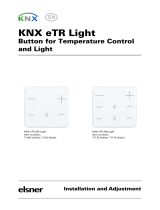
➢ Dimming Pattern: [Linear / Curve 1 / Curve 2]. Figure 10 shows the different
regulation curves for each load type.
➢ Dimming Mode: [Trailing Edge / Leading Edge].
Important: please configure these options with caution in order to obtain the
best results. Refer to section 1.2 for details.
Figure 10 Dimming Patterns for LED and CFL loads.
0%
10%
20%
30%
40%
50%
60%
70%
80%
90%
100%
0% 20% 40% 60% 80% 100%
% DIMMING
% ETS VALUE
LINEAL
LED 1
LED 2
CFL 1

DIMinBOX DX1 / DX2 / DX4
http://www.zennio.com Technical Support: http://support.zennio.com
19
With independence of the load type, the following parameters will be shown:
Adjust Characteristic Curve [disabled/enabled]: see section 2.2.1.1.
Dimming Speed: sets the type of response (immediate or progressive; see
section 2.1) for the different control orders.
➢ Absolute Dimming [At Once / Smooth 1 / Smooth 2].
➢ Relative Dimming [At Once / Smooth 1 / Smooth 2].
➢ On/Off [At Once / Smooth 1 / Smooth 2].
Memory Function: On Light Level: sets the desired response for the switch-
on orders through the object “[Cx] On/Off”:
➢ [Maximum]: maximum light level; that is, a “memory” switch-on.
➢ [Previous]: previous light level before last switch-off.
➢ [Defined by object] (only for DIMinBOX DX1 / DX4): light level defined by
the object “[Cx] Memory Function: Light Level”. After download, the object
will be initialised to the maximum level.
If the option "Previous" or "Object Defined" is selected, the Set Maximum after
Second Order (only for DIMinBOX DX1 / DX4) or Overwrite the Memory
Value (only for DIMinBOX DX2) parameter will be displayed, which will enable
the maximum light level at a new order.
Enable Economical Mode [Yes / No]: enables (“Yes”) or disables (“No”) an
internal reduction to the light level (and therefore the energy consumption) by
a certain coefficient.
➢ Maximum Dimming Value [20…80…100][%]. The lower the maximum
dimming value, the greater the consumption reduction.
Enable Minimum [Yes / No]. In case of selecting “Yes”:
➢ Maximum Dimming Value [0…10…50][%].
On the other hand, the following communication objects will be available:
“[Cx] On/Off”: one-bit object for the reception of switch orders from the bus.
One “1” will switch the light on, while one “0” will switch it off. The dimming

DIMinBOX DX1 / DX2 / DX4
http://www.zennio.com Technical Support: http://support.zennio.com
20
speed will be “At Once”, “Smooth 1” or “Smooth 2” according to the parameters,
as explained above.
“[Cx] Absolute Dimming”: 1-byte object for the reception of the desired light
level (in terms of percentage) from the bus. Once again, the dimming speed
will be “At Once”, “Smooth 1” or “Smooth 2” depending on the parameterisation,
as explained above.
“[Cx] Relative Dimming”: four-bit object for the reception of dimming orders
from the bus. The value of the object will be interpreted as the desired step
(brighter or darker), according to the KNX standard. The values “0” and “8”
interrupt the current regulation.
Value
Response
0x0 (0)
Stop light dimming
0x1 (1)
Decrease the light level by 100%
0x2 (2)
Decrease the light level by 50%
0x3 (3)
Decrease the light level by 25%
0x4 (4)
Decrease the light level by 12%
0x5 (5)
Decrease the light level by 6%
0x6 (6)
Decrease the light level by 3%
0x7 (7)
Decrease the light level by 1%
0x8 (8)
Stop light dimming
0x9 (9)
Increase the light level by 100%
0xA (10)
Increase the light level by 50%
0xB (11)
Increase the light level by 25%
0xC (12)
Increase the light level by 12%
0xD (13)
Increase the light level by 6%
0xE (14)
Increase the light level by 3%
0xF (15)
Increase the light level by 1%
Table 1 Responses to the 4-bit Dimming Orders.
The dimming speed will be “At Once”, “Smooth 1” or “Smooth 2” depending on
the parameterisation, as explained above.
“Smooth Dimming Time 1” (provided that Smooth Dimming Time Objects
has been enabled; see section 2.1): 1-byte object that allows the value of the
"Smooth 1" control time to be changed in seconds via the bus. This modification
will affect all actions where this time has been set. The time range of the objects
to modify the regulation times (0 - 65535s) is greater than the maximum
/