Page is loading ...


W I L S O N A U D I O S P E C I A L T I E S , I N C .

W I L S O N A U D I O S P E C I A L T I E S , I N C .
WILSON AUDIO SPECIALTIES
X-1/GRANDSLAMM
OWNER’S MANUAL

W I L S O N A U D I O S P E C I A L T I E S , I N C .
Wilson Audio is a registered trademark of Wilson Audio Specialties Inc.
X-1/Grand Slamm is a registered trademark of Wilson Audio Specialties Inc.
This manual was produced by the Wilson Audio Engineering Department in cooperation with Sales and Marketing. The infor
-
mation contained here in is subject to change without notice. Current Revision 2.0, Feb. 2000 if you are in need of a more recent
manual please contact your dealer.

W I L S O N A U D I O S P E C I A L T I E S , I N C .
i
T A B L E O F C O N T E N T S
TABLE OF GRAPHICS ............................................................................................................................................III
COMPONENTS AND DIMENSIONS ............................................................................................................................................. IV
SECTION 1.0- ROOM ACOUSTICS ........................................................................................................................... 1-1
FINAL LISTENING ROOM SETUP (VOICING) ............................................................................................................................. 1-1
SECTION 1.1-ROOM REFLECTIONS ....................................................................................................................... 1-2
SLAP-ECHO .......................................................................................................................................................................... 1-2
STANDING WAVES ................................................................................................................................................................. 1-3
COMB FILTER EFFECT ............................................................................................................................................................ 1-4
SECTION 1.2-RESONANCE’S .................................................................................................................................... 1-5
STRUCTURAL RESONANCE ..................................................................................................................................................... 1-5
AIR VOLUME RESONANCE .................................................................................................................................................... 1-5
SECTION 1.3-IN YOUR ROOM .................................................................................................................................. 1-6
ROOM SHAPES ..................................................................................................................................................................... 1-6
SPEAKER PLACEMENT VS. LISTENING POSITION ....................................................................................................................... 1-7
CHOOSING A LISTENING POSITION ......................................................................................................................................... 1-7
SPEAKER ORIENTATION ......................................................................................................................................................... 1-8
SUMMARY ............................................................................................................................................................................ 1-9
SECTION 2.0-CARE OF THE X-1/GRAND SLAMM ............................................................................................... 2-1
PAINTED OR WOOD FINISH .................................................................................................................................................... 2-1
BREAK IN PERIOD ................................................................................................................................................................ 2-2
SECTION 2.1 ENCLOSURE CONSTRUCTION ....................................................................................................... 2-2
MATERIAL ........................................................................................................................................................................... 2-2
ADHESIVE ............................................................................................................................................................................ 2-3
DEPTH OF DESIGN ................................................................................................................................................................ 2-3
CONLCUSION ........................................................................................................................................................................ 2-3
SECTION 3.0-UNCRATING THE X-1/GRAND SLAMM ........................................................................................ 3-1
INITIAL CHECK ..................................................................................................................................................................... 3-1
UNCRATING THE WOOFER CABINETS ...................................................................................................................................... 3-1
MATERIALS REQUIRED .......................................................................................................................................................... 3-1
UNPACKING THE WOOFER ..................................................................................................................................................... 3-1
UNCRATING THE FASCIA ASSEMBLY ....................................................................................................................................... 3-2
UNCRATING THE UPPER ARRAY MODULES .............................................................................................................................. 3-2
CRATE CONTENTS: CHECKLIST .............................................................................................................................................. 3-4
ASSEMBLE YOUR SPIKES FOLLOWING THESE STEPS: .................................................................................................................. 3-5
SECTION 4.0- X-1/GRANDSLAMM INITIAL ASSEMBLY .................................................................................... 4-1
TIMING BLADES ................................................................................................................................................................... 4-1
CONNECT THE TIMING BLADES TO THE WOOFER CABINET AS FOLLOWS: ..................................................................................... 4-2

W I L S O N A U D I O S P E C I A L T I E S , I N C .
M A X X O W N E R ’ S M A N U A L
ii
TABLE OF CONTENTS CONT.
SECTION 4.1-MOUNTING THE UPPER ARRAY MODULES ......................................................................... 4-3
MATERIALS REQUIRED .................................................................................................................................................... 4-3
MOUNTING PROCEDURE .................................................................................................................................................. 4-3
MOUNTING THE UPPER CROSSOVER ................................................................................................................................. 4-5
CONNECTING THE UPPER RANGE SIGNAL CABLE .............................................................................................................. 4-7
CONNECTOR PLATE JUMPER ............................................................................................................................................ 4-8
SECTION 4.2- GEOMETRIC TIME DOMAIN ALIGNMENT ......................................................................... 4-9
MATERIALS REQUIRED .................................................................................................................................................... 4-9
PULSE ALIGNMENT ......................................................................................................................................................... 4-9
ROOM SETUP ................................................................................................................................................................. 4-9
ALIGNMENT PROCEDURE ............................................................................................................................................... 4-10
SECTION 4.3- TIME ALIGNMENT EXAMPLE ............................................................................................... 4-12
GIVEN: ........................................................................................................................................................................ 4-12
SECTION 4.4- LOCKING DOWN UPPER ARRAY .......................................................................................... 4-14
MATERIALS REQUIRED .................................................................................................................................................. 4-14
LOCKING DOWN THE UPPER ARRAY ............................................................................................................................... 4-14
SECTION 4.5- SPIKE INSTALLATION ............................................................................................................. 4-15
MATERIALS REQUIRED .................................................................................................................................................. 4-15
INSTALLATION PROCEDURE ............................................................................................................................................ 4-15
LEVELING THE X-1 GRAND SLAMM ............................................................................................................................... 4-18
SECTION 4.6-CHECKING THE IMAGE HEIGHT ......................................................................................... 4-19
SECTION 4.7-ATTACHING THE FASCIA’S .....................................................................................................
4-20
REQUIRED MATERIALS: ................................................................................................................................................. 4-20
ATTACHMENT PROCEDURE: ........................................................................................................................................... 4-20
SECTION-5.0 WARRANTY INFORMATION ..................................................................................................... 5-1
SECTION 6.0 SETTING UP DIFFICULTIES AND TROUBLESHOOTING ...................................................
6-1
SECTION 7.0- SPECIFICATIONS ........................................................................................................................
7-1
APPENDIX A- TIMING CHARTS ........................................................................................................................
A-1

W I L S O N A U D I O S P E C I A L T I E S , I N C .
T A B L E O F G R A P H I C S
iii
FIGURE 1- WOOFER, STAND, AND MAIN CROSSOVER ........................................................................................... 3-1
FIGURE 2- TIMING BLADE AND FASCIA ............................................................................................................... 3-2
FIGURE 3- UPPER ARRAY MODULES ................................................................................................................... 3-3
FIGURE 4- UPPER ARRAY MODULES ................................................................................................................... 3-3
FIGURE 5- UPPER ARRAY MODULES ................................................................................................................... 3-3
FIGURE 6- UPPER CROSSOVER ............................................................................................................................ 3-3
FIGURE 7- TILTING POLES .................................................................................................................................. 3-3
FIGURE 8- X-1 SPIKES ...................................................................................................................................... 3-5
FIGURE 9- NUMBER LOCATIONS ON FASCIA ......................................................................................................... 4-1
FIGURE 10- EXPLODED VIEW OF FASCIA ............................................................................................................. 4-1
FIGURE 11- ATTACHING THE TIMING BLADE TO WOOFER ..................................................................................... 4-2
FIGURE 12- UPPER BOLT ASSEMBLY ................................................................................................................... 4-3
FIGURE 13- INSTALLING THE UPPER ARRAY ........................................................................................................ 4-3
FIGURE 14- INSTALLED UPPER ARRAY MODULES. ............................................................................................... 4-4
FIGURE 15- TIGHTENING THE UPPER ARRAY BOLT ............................................................................................... 4-4
FIGURE 16- INSTALLING THE UPPER CROSSOVER.. ............................................................................................... 4-5
FIGURE 17- POSITIONING THE UPPER CROSSOVER ................................................................................................ 4-5
FIGURE 18- WIRING THE UPPER ARRAY .............................................................................................................. 4-6
FIGURE 19- MAIN CONNECTOR PLATE ................................................................................................................ 4-7
FIGURE 20- LISTENING DISTANCE AND EAR HEIGHT ............................................................................................ 4-9
FIGURE 21- READING THE MARKINGS ON THE TIMING BLADE ............................................................................ 4-11
FIGURE 22- LMRM ALIGNMENT CHART .......................................................................................................... 4-13
FIGURE 23- TIGHTENING THE UPPER ARRAY BOLTS ........................................................................................... 4-14
FIGURE 24- HOLE COVER LOCATIONS ON BASE/STAND ...................................................................................... 4-15
FIGURE 25- TILTING THE X-1 FOR SPIKE INSTALLATION ..................................................................................... 4-15
FIGURE 26- INSTALLING THE SPIKES. ................................................................................................................ 4-16
FIGURE 27- SPIKES INSTALLED FIRST SIDE ........................................................................................................ 4-16
FIGURE 28- INSTALLING SPIKES SECOND SIDE ................................................................................................... 4-17
FIGURE 29- FASCIA BOLT LOCATIONS ............................................................................................................... 4-20
FIGURE 30- FINISHED UPPER ARRAY ................................................................................................................ 4-20
TABLE OF GRAPHICS

W I L S O N A U D I O S P E C I A L T I E S , I N C .
iv
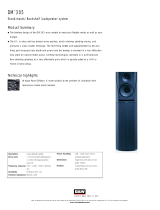
X-1/ GRAND SLAMM - COMPONENTS AND DIMENSIONS
UPPER MID-FRE-
QUENCY
MODULE
FASCIA ASSEMBLY
LOWER MID- FRE-
QUENCY MODULE
HIGH FREQUENCY
MODULE
UPPER ARRAY
CROSSOVER
WOOFER ENCLO-
SURE
STAND/BASE
ENCLOSURE
15.25 IN.
39 CM
9 IN.
23 CM
16.5 IN.
42 CM
25.25 IN.
64 CM
72 IN.
183 CM
UPPER ARRAY
CROSSOVER

W I L S O N A U D I O S P E C I A L T I E S , I N C .


1
R O O M A C O U S T I C S

W I L S O N A U D I O S P E C I A L T I E S , I N C .

W I L S O N A U D I O S P E C I A L T I E S , I N C .
S e c t i o n 1 - R o o m A c o u s t i c s
You are surely excited about setting up your X-1/GrandSLAMM loudspeakers and doing some lis
-
tening, but before you begin we would like to discuss some of the important room acoustical information
that will help you set up your loudspeakers properly.
FINAL LISTENING ROOM SETUP (VOICING)
Your X-1/GrandSLAMM loudspeakers will give you years of music satisfaction. However, their
high performance characteristics and abilities can only be fully appreciated with the proper acoustical setup.
The following section will present some guidelines on room acoustics and their interactions with
loudspeakers. We will also offer some detailed suggestions on the setup of the X-1/GrandSLAMMs, but
we strongly suggest that you have your local Wilson Audio dealer perform the final speaker “voicing” for
you. They are specially trained in setting up Wilson loudspeakers and will ensure that you realize the full
value of your purchase.
1-1
SECTION 1.0 ROOM ACOUSTICS

W I L S O N A U D I O S P E C I A L T I E S , I N C .
SECTION 1.1 ROOM REFLECTIONS
There are 3 commonly encountered room reflection problems: slap echoʼs, standing-
waves, and comb filter effect.
SLAP ECHO
Probably the most obnoxious form of reflection is called “slap echo.” With slap echo, primarily mid-
range and high frequency sounds reflect off of two parallel hard surfaces. The sound literally reverberates
back and forth until it is finally dissipated over time. You can test for slap echo in any room by clapping
your hands sharply in the middle of the room and listening for the characteristic sound of the echo in the
mid-range. Slap echo destroys the sound quality of a stereo system in two ways:
§ It adds harshness to the upper mid-range and treble through energy time storage.
§ It destroys the delicate phase relationships, which help to establish an accurate sound stage.
Slap echo is a common acoustical problem in the typical domestic listening room because most of
these rooms have walls with a hard, reflective nature, usually being only occasionally interrupted by curtains
or drapes. The best solution to eliminate slap echo is non-parallel walls, this is because non-parallel walls do
not support slap echo, but rather allow the sound to diffuse. Otherwise, slap echo can be controlled entirely
by the application of absorptive materials to the hard surfaces, such as:
§ Sonex
§ Airduct board
§ Cork panels to the hard surfaces.
§ Large ceiling to floor drapes
§ Carpeting to wall surfaces.
In many domestic listening environments, heavy stuffed furnishings are the primary structural con-
trol to slap echo. Unfortunately, their effectiveness is not predictable. Diffusers are
1-2
X-1/ GRAND SLAMM OWNER’S MANUAL

W I L S O N A U D I O S P E C I A L T I E S , I N C .
sometimes also used to very good subjective effect, particularly in quite large rooms. Sound absorbent ma-
terials such as described above will alter the tonal characteristic of the room by making it sound “deader,”
less “bright and alive” and “quieter.” These changes also make the room more pleasant for conversation.
Diffusers, on the other hand, tend to not change the tonal balance characteristic of the room, but make the
sound smoother and more open.
STANDING WAVES
Another type of reflection phenomenon is “standing waves.” Standing waves cause the unnatural
boosting or accentuation of certain frequencies, typically in the bass, to be found at certain discreet locations
on the room. A room generating severe standing waves will tend to make a loudspeaker sound one way
when placed in one location and entirely different when placed in another. The effects of standing waves on
a loudspeaker’s performance primarily as follows:
§ Tonal balance
§ Resolution of low-level detail
§ Sound-staging
Standing waves are more difficult to correct than slap echo because they tend to occur at a lower
frequency, whose wavelength is long enough to be ineffectively controlled by absorbent materials such as
Sonex. Moving speakers about slightly in the room is, for most people, their only control over standing
waves. Sometimes a change of placement of as little as two or three inches can dramatically alter the tonal
balance of a small system. Fortunately, minor low frequency standing waves are well controlled by posi-
tioning ASC tube traps in the corners of the room. Very serious low frequency accentuation usually requires
a custom-designed bass trap system.
Low frequency standing waves can be particularly troublesome in rooms constructed of concrete or
brick. These materials trap the bass in the room, unless it is allowed to leak out of the room, through win-
dows and doors.
S E C T I O N 1 . 1 - R O O M R E F L E C T I O N S
1-3
X-1/ GRAND SLAMM OWNER’S MANUAL

W I L S O N A U D I O S P E C I A L T I E S , I N C .
In general, placement of the speaker in a corner will excite the maximal number of standing waves
in a room, and is to be avoided for most direct radiator, full range loudspeaker systems. Some benefit is
achieved by placing the stereo pair of loudspeakers slightly asymmetrically in the listening room. This is so
that the standing waves caused by the distance between one speaker, its adjacent walls and floors are not the
same as the standing wave frequencies excited by the dimensions in the other channel.
COMB FILTER EFFECT
The comb filter effect is a special type of standing wave noticeable primarily at higher frequencies
and shorter wavelengths.
Acoustical comb filtering occurs when sound from a single source, such as a loudspeaker, is di-
rected toward a microphone or listener from a distance. The first sound to reach the microphone is the
direct sound, followed by a delayed, reflected sound. At certain frequencies cancellation occurs, because
the reflected sound lags in phase relative to the direct sound. This cancellation is most apparent where the
two are 180 degrees out of phase. Further, there is augmentation at other frequencies where the direct and
the reflected sounds arrive in phase. Because it is a function of wavelength, the comb filter effect will notch
out portions of the audio spectrum at regular octave-spaced intervals. The subjective effect of comb filter
effects is as follows:
§ Added roughness to the sound
§ Reduction of harmonic richness
§ Smearing of lateral sound stage image focus and placement
Comb filter effects are caused by side wall reflections. These are best controlled by careful speaker
placement and by the placement of Sonex or air duct panels to the part of the wall where the reflection oc-
curs.
1-4
X-1/ GRAND SLAMM OWNER’S MANUAL

W I L S O N A U D I O S P E C I A L T I E S , I N C .
Resonance in listening rooms is generally caused by two sources:
§ Structures within the listening room
§ The volume of the air itself in the listening room
STRUCTURAL RESONANCE
Structural resonance’s are familiar to most people as buzzes and rattles, but this type of resonance
usually only occurs at extremely high volume levels, and is usually masked by the music. In many wood
frame rooms the most common type of structural resonance problem is “booming” of walls and floors. You
can test for these very easily by tapping the wall with the palm of your hand or stomping on the floor. To
give you an idea of what the perfect wall would sound like, imagine rapping your hand against the side of
a mountain. Structural wall resonance’s generally occur in the low to mid-bass frequencies and add tonal
balance fullness to any system played in that room. They too are more prominent at louder levels, but
their contribution to the sound of the speaker is more progressive. Rattling windows, picture frames, lamp
shades, etc. can generally be silenced with small pieces of caulk or with blocks of felt. However, short of
actually adding additional layers of sheet rock to flimsy walls, there is little that can be done to eliminate
wall resonance’s.
AIR VOLUME RESONANCE
The volume of air in a room will also resonate at a frequency determined by the size of the
room. Larger rooms will resonate at a lower frequency than will smaller rooms. Air volume res-
onanceʼs, wall panel resonanceʼs, and low frequency standing waves, together, combine to form
a low frequency coloration in the sound. At its worst, it is a grossly exaggerated fullness, which
tends to obscure detail and distort the natural tonal balance of the speaker system.
S E C T I O N 1 . 2 - RESONANCE’S
SECTION 1.2 RESONANCE’S
1-5
X-1/ GRAND SLAMM OWNER’S MANUAL

W I L S O N A U D I O S P E C I A L T I E S , I N C .
Occasionally, however, there is just enough resonance to give a little added warmth to the sound… an addi-
tion some listeners prefer. Tube traps manufactured by the ASC Corporation are effective in reducing some
of this low frequency room coloration. While, custom designed bass traps, such as perforated Helmholtz
resonators, provide the greatest degree of low frequency control.
SECTION 1.3- IN YOUR ROOM
ROOM SHAPES
There are three basic shapes for most rooms: square, rectangular, and L-shaped. A perfectly square
room is the most difficult room to set up speakers in because, by virtue of its shape, square rooms are the
perfect medium for building and sustaining standing waves. Standing waves are pressure waves created by
the integration of sound and opposing, parallel walls which accentuate particular frequencies. They heavily
influence the music played by loudspeakers, greatly diminishing the listening experience.
Long, narrow rectangular rooms also pose their own special acoustical problems for speaker setup.
They have the ability to set up several standing wave nodes, which will have different standing wave fre-
quency exaggerations depending on where you are sitting. Additionally, these long rooms are often quite
lean in the bass near the center of the room. Rectangular rooms are still preferred to square rooms because
by having two sets of dissimilar length walls, standing waves are not as strongly reinforced and will dis-
sipate more quickly than in a square room. In these rooms the preferred speaker position for spatial place-
ment and midrange resolution would be on the longer walls. Bass response would be reinforced by speaker
placement on the short walls.
In many cases L-shaped rooms offer the best environment for speaker setup. Ideally, speakers
should be set up along the primary (longest) leg of the room. They should fire from the end of the leg (short
wall) toward the bend, or they should be along the longest wall, with the speaker furthest to the bend being
inside of the bend. In this way both speakers are firing the same distance to the back wall. The asymmetry
of the walls in L-shaped rooms resists the buildup of standing waves.
1-6
X-1/ GRAND SLAMM OWNER’S MANUAL

W I L S O N A U D I O S P E C I A L T I E S , I N C .
S E C T I O N 1 . 3 - I N Y O U R ROOM
SPEAKER PLACEMENT VS. LISTENING POSITION
The location of your listening position is as important as the careful setup of your X-1/
GrandSLAMM speakers in your room. The listening position should ideally be no more than 1.1
to 1.25 times the distance between the tweeters on each speaker. Therefore, in a long rectangu-
lar room of 12ʼ x 18ʼ, if the speaker tweeters are going to be 9ʼ apart, you should be sitting 9ʼ11ʼʼ
to 11ʼ3ʼʼ from the speaker. This would be about halfway down the long axis of the room.
Many people place the speakers on one end and sit at the other end of the room, this will not yield
the finest sound. Carefully consider your listening position. Our experience has shown that any listening
position which places your head closer than 14” to a room boundary will diminish the sonic results of your
listening.
CHOOSING A LISTENING POSITION
Decide where you want your favorite listening position to be. Please remember that your X-1/
GrandSLAMM will fill almost any room with the most beautiful sound available. However, for the phase
delay correction advantage, we want to ensure that you get all the benefits that are built into this design. For
this purpose we have designed the following questions:
What is the main purpose of your X-1/GrandSLAMM? Is it for a listening room dedicated to
2-channel audio? If yes, you should choose your position carefully to yield the finest sound. Wilson Au-
dio uses a formula: The distance between the 2 woofers of each channel times 1.2 equals the distance you
should sit from each loudspeaker.
For instance, if you measure the distance between the center of the left channel woofer to the cor-
responding right channel woofer and it is equal to 10 feet, multiply it by 1.2. This means that you should sit
12 feet from each X-1/GrandSLAMM.
1-7
X-1/ GRAND SLAMM OWNER’S MANUAL

W I L S O N A U D I O S P E C I A L T I E S , I N C .
Are your X-1/GrandSLAMM’s dedicated for a home theater?
Are you going to sit on a couch, or will there be multiple rows of chairs?
If it is a couch, you should center the loudspeakers on the center position of the couch.
Multiple rows of chairs - In this case you should dedicate the 1.2 times equation on your second row
of seating. Now more people will enjoy the power of your X-1/GrandSLAMMs .
Do you still want to listen to 2 channel music at its highest quality? In this way you can enjoy a
great time aligned sound from that second seat.
SPEAKER ORIENTATION
Speaker placement and orientation are two of the most important considerations in obtaining supe-
rior sound. The first thing you need to do is eliminate the side walls as a sonic influence in your system.
Speakers placed too close to the side walls will suffer from a strong primary reflection. This can cause out-
of-phase cancellations, or comb filtering, which will cancel some frequencies and change the tonal balance
of the music. A good place to start is with the speakers about 18” from each wall and, if you need to move
them relative to the side wall, move them away from the wall, not closer.
A very important aspect of speaker placement is how far from the back wall to place the speakers.
The closer to the back wall the more pronounced the low bass energy and centering of the image will be.
However, this comes at a definite reduction in stage size and bloom, as well as a deterioration of upper bass
quality. You must find the proper balance of these two factors, but remember, if you are partial to bass re-
sponse or air and bloom, do not overcompensate your adjustments to maximize their effects. Overbalanced
systems are sometime pleasing in the short term, but long term satisfaction is always achieved through
proper balance.
The X-1/GrandSLAMM is designed for maximum phase coherence and pulse replication
accuracy when they are aimed directly at the listener or microphone. Thus, your X-1/Grand-
SLAMM should be “toed in.” In other words, the listener, when seated in the listening position,
should just barely see the surface of the inner side of X-1/GrandSLAMM. Toeing in the speakers
provides dramatic improvements in resolution of low level detail in the midrange, as well as dra-
matic improvements in sound staging performance.
1-8
X-1/ GRAND SLAMM OWNER’S MANUAL
/