LG LZ-H200GBA2 User manual

Type
User manual
www.lg.com
Please read this installation manual completely before installing the product.
Installation work must be performed in accordance with the national wiring
standards by authorized personnel only.
Please retain this installation manual for future reference after reading it
thoroughly.
[
Representative
]
LG Electronics Inc. EU Representative : LG Electronics European
Shared Service Center B.V. Krijgsman 1, 1186 DM Amstelveen, The Netherlands
[Manufacturer] LG Electronics Inc. Changwon 2nd factory 84, Wanam-ro, Seongsan-gu,
Changwon-si, Gyeongsangnam-do, KOREA
INSTALLATION MANUAL
AIR
CONDITIONER
VENTILATOR
Original instruction
P/NO : MFL67855502
ITALIANO
ESPAÑOL
FRANÇAIS
DEUTSCH
ΕΛΛΗΝΙΚΆ
ČEŠTINA
NEDERLANDS
POLSKI
LIMBA ROMÂNĂ
ENGLISH
2 Ventilator
Ventilator Installation Manual
TABLE OF CONTENTS
Safety Precautions...............3
Introduction ..........................8
Symbols used in this
Manual.................................8
Feature Dimension
Diagram...............................8
Installation ..........................13
Installation Map .................13
Installation of Main Body ...16
Connection of Duct............16
Method to Connect
Power Cord .......................18
How to connect Remote
Controller(Accessory) .......19
Name and Function of
Remote Controller .............19
Installation instruction........20
Group control.....................22
Installer Setting -How to enter
installer setting mode ........24
How to connect Central
Controller(Accessory) .......26
Trial Operation....................27
Method to Operate and Select
Air Volume –Ventilation Single
Operation
............................27
Method to Operate and Select
Air Volume – Interlinked
Operation with Ventilation
. ...28
In case of finding a problem
at a trial operation..............29
Model Designation.............30
Airborne Noise Emission ...30
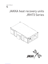
• Screws
• Nuts
• Ceiling Fixing Bolt(M10~12)
• Washer
• Aluminium Tape
• Screws
• Screw Driver
• Spanner
• Cutter
• Cutter
• Screw Driver
Installation
Requirements
Required Parts Required Tools
Safety Precautions
Installation Manual 3
Safety Precautions
To prevent injury to the user or other people and property damage, the following instructions
must be followed.
n Incorrect operation due to ignoring instruction will cause harm or damage. The seriousness is
classified by the following indications.
n Meanings of symbols used in this manual are as shown below.
WARNING
CAUTION
This symbol indicates the possibility of death or serious injury.
This symbol indicates the possibility of injury or damage.
Be sure not to do.
Be sure to follow the instruction.
WARNING
n Installation
Do not use a defec-
tive or underrated
circuit breaker. Use
this appliance on a
dedicated circuit.
• There is risk of fire or
electric shock.
For electrical work, con-
tact the dealer, seller, a
qualified electrician, or
an Authorized Service
Center.
• Do not disassemble or
repair the product.
There is risk of fire or
electric shock.
Always ground the
product.
• There is risk of fire or
electric shock.
Install the panel and
the cover of control
box securely.
• There is risk of fire or
electric shock.
Always install a dedi-
cated circuit and
breaker.
• Improper wiring or
installation may cause
fire or electric shock
Use the correctly rated
breaker or fuse.
• There is risk of fire or
electric shock.
ENGLISH
Safety Precautions
4 Ventilator
For installation, always
contact the dealer or
an Authorized Service
Center.
• There is risk of fire,
electric shock, explo-
sion, or injury.
Do not install the
product on a defec-
tive installation
stand.
• It may cause injury,
accident, or damage to
the product.
Do not let the product
run for a long time when
the humidity is very
high and a door or a
window is left open.
• Moisture may condense
and wet or damage fur-
niture.
For re-installation of the
installed product,
always contact the deal-
er or an Authorized
Service Center.
• There is risk of fire,
electric shock, explo-
sion or injury.
Do not open the
maintenance cover of
the main body during
operation.
• Otherwise, it may cause
electrical shock.
Use the outdoor air
suction hole with the
net installed to
ensure that birds
could not come in.
• Remove estrange
things like the bird’s
nest. Otherwise, it may
cause scarcity of indoor
oxygen.
Do not modify or
extend the power
cable.
• There is risk of fire or
electric shock.
Do not install,
remove, or re-install
the unit by yourself
(customer).
• There is risk of fire,
electric shock, explo-
sion, or injury.
Be cautious when
unpacking and
installing the prod-
uct.
• Sharp edges could
cause injury.
Safety Precautions
Installation Manual 5
ENGLISH
Install the air intake
where polluted air
can not be directly
sucked in.
• It may cause various
accidents, including suf-
focation, due to the suc-
tion of harmful
gasses(CO, etc.)
Do not install this
product in a refriger-
ated warehouse,
heated swimming
pool or other location
where the tempera-
ture and humidity are
significantly differ-
ent.
• There is risk of electrical
shock, malfunctioning.
Install this product in
an environment
where the tempera-
ture ranges from –
10°C to +45°C and
the relative humidity
is less than 80%. It
condensation is
expected to form,
heat up the fresh out-
side air using a duct
heater etc.
Install this product in
and environments
where the outside air
intake meets the fol-
lowing conditions:
temperature range is
between –15°C and
+40°C and the rela-
tive humidity is 80%
or less.
Use the designated
electrical wires for
the terminal board
connections, and
connect the wires
securely so that they
will not become dis-
connected. (Failure
to ensure proper
connections may
cause fire.)
When passing metal
ducts through wood-
en buildings clad
with metal laths, wire
laths or metal, these
ducts must be
installed in such a
way that they will not
make electrical con-
tact with the metal
laths, wire laths or
metal sheets. (Power
leakage can cause
ignition)
6 Ventilator
Be cautious that water could not
enter the product.
• There is risk of fire, electric shock, or
product damage.
Turn the breaker off when clean-
ing or maintaining the product.
• There is risk of electric shock.
The outside ducts must be tilted
at a gradient (1/30 or more) down
toward the outdoor area from the
ventilator unit, and properly insu-
lated. (The entry of rain water may
cause power leaks, fire or damage
to household property.)
Glove should be worn when doing
the installation work. (There is
risk of injury.)
Avoid fire equipment
• There is risk of fire.
When the product is
soaked (flooded or
submerged), contact
an Authorized Service
Center.
• There is risk of fire or
eletric shock.
Don't touch a dedicat-
ed circuit or breaker
with wet hands.
• There is risk of electric
shock.
n Operation
When the product is
not be used for a long
time, disconnect the
power supply plug or
turn off the breaker.
• There is risk of product
damage or failure, or
unintended operation.
Do not store or use
flammable gas or
combustibles near
the product.
• There is risk of fire or
failure of product.
When flammable gas
leaks, turn off the gas
and open a window for
ventilation before turn
the product on.
• Do not use the tele-
phone or turn switches
on or off.
There is risk of explo-
sion or fire
Safety Precautions
Installation Manual 7
ENGLISH
Don't connect the ground
wire to the window frame
or water cock.
• There is risk of electric
shock.
Do not install the product
at a smoky and oily place
like kitchen or factory.
• Otherwise. oil may
adhere to the filter or
heating exchanger and
cause trouble.
Install the product in
an insulated space
from outdoor air.
In case of installing the prod-
uct outside of the insulated
layer, dewing occurs inside of
the main body in winter.And it
causes electrical shock or
falling of condensed water.
n Installation
CAUTION
Keep level even
when installing the
product.
• To avoid vibration or
water leakage.
Use two or more peo-
ple to lift and trans-
port the product.
• Avoid personal injury.
Do not install the prod-
uct where it will be
exposed to sea wind
(salt spray) directly.
It may cause corrosion on
the product. Corrosion, par-
ticularly on the condenser
and evaporator fins, could
cause product malfunction
or inefficient operation.
Use a soft cloth to
clean. Do not use
harsh detergents, wax
or thinner, etc.
• Otherwise, color or sur-
face of the oroduct mav
deteriorate.
Clean the filter and the
heat exchanger regu-
larly and use the
gloves for cleaning.
Adhering to a mass of
dust may cause the dete-
rioration of air volume.
Do not use the product for
special purposes, such as
preserving foods, works of
art, etc. It is a consumer
ventilator, not a precision
refrigeration system.
• There is risk of damage
or loss of property.
n Operation
Do not block the inlet or outlet of
air flow.
• It may cause product failure.
Do not step on or put anyting on
the product.
• There is risk of personal injury and
failure of product.
Safety Precautions
Introduction
8 Ventilator
A J
G
H
K L
B
E
C
F
D
Suspension Fixture
Blower for Supply Air
Blower for Exhaust
(Exhaust Air) (Supply Air)
(Return Air)
(Outdoor Air)
Air
SA
RA
EA
OA
Feature Dimension Diagram
Model
605 570 185 525 603 40 100 97 184 90 394 100 22
A B C D E F G H J K L kg
LZ-H015GBA2
Figure Duct Pitch Weight
Pitch of Suspension
Fixture
Duct Connection Flange
Nominal
Diameter
Model : LZ-H015GBA2
Unit : mm
h
It necessary to secure sufficient space for maintenance more than the dimensions described in the
product service.
This symbol alerts you to the risk of electric shock.
This symbol alerts you to hazards that could cause harm to the
product.
This symbol indicates special notes.
NOTICE
Symbols used in this Manual
Introduction
Introduction
Installation Manual 9
A K
H
J
Suspension Fixture
Blower for Exhaust Air
Maintenance Cover
Blower for Supply Air
F
B
L
M
E
EA
OA
SA
RA
Total Heat
Exchanger
Control Box
Air Filter
C
G
D
(Exhaust Air)
(Supply Air)
(Return Air)
(Outdoor Air)
Model : LZ-H025GBA2 / LZ-H035GBA2
Model
750 680 250 850 657 711 40 150 146 155 50 502 89.2 32
A B C D E F G H J K L M kg
LZ-H025GBA2
LZ-H035GBA2
Figure Duct Pitch Weight
Pitch of Suspension
Fixture
Duct Connection Flange
Nominal
Diameter
Unit : mm
h
It necessary to secure sufficient space for maintenance more than the dimensions described in the
product service.
ENGLISH
Introduction
10 Ventilator
Blower for Exhausting Air
Blower for Supplying Air
Control box
Maintenance Cover
Suspension Fixture
Total Heat Exchanger
Air Filter
F
RA
(Return Air)
SA
(Supply Air )
OA
(Outdoor Air)
EA
(Exhaust Air)
Model : LZ-H050GBA2
Model
1014 988 273 939 1025 135 200 194 252 96 590 198 44
A B C D E F G H J K L kg
LZ-H050GBA2
Figure Duct Pitch Weight
Pitch of Suspension
Fixture
Duct Connection Flange
Nominal
Diameter
Unit : mm
h
It necessary to secure sufficient space for maintenance more than the dimensions described in the
product service.
Introduction
Installation Manual 11
Blower for Exhausting Air
Blower for
Supplying Air
Control box
Suspension Fixture
Maintenance Cover
Total Heat Exchange Element
Air Filter
F
RA
(Return Air)
SA
(Supply Air)
OA
(Outdoor Air)
EA
(Exhaust Air)
Model : LZ-H080GBA2 / LZ-H100GBA2
Model
1062 1140 365 987 1176 180 250 242 253 98 513 481 56
A B C D E F G H J K L kg
LZ-H080GBA2
LZ-H100GBA2
Figure Duct Pitch Weight
Pitch of Suspension
Fixture
Duct Connection Flange
Nominal
Diameter
Unit : mm
h
It necessary to secure sufficient space for maintenance more than the dimensions described in the
product service.
ENGLISH
Introduction
12 Ventilator
Control Box
Maintenance Cover
EA
OA
RA
SA
B
C
D
E
N
O
F
M
Air Filter
Total Heat Exchanger
K
L
J
G
H
Model : LZ-H150GBA2 / LZ-H200GBA2
Model
1313 1140 738 987 1176 339 242 253 98 340 350 140
AB
CDE
F
G H J K L (kg)
LZ-H150GBA2
LZ-H200GBA2
Figure Weight
Pitch of Suspension
Fixture
Duct Connection Flange
Unit: mm
h
It necessary to secure sufficient space for maintenance more than the dimensions described in the
product service.
Installation Manual 13
Installation
RA Grille
Ventilator
SA Grille
Inspection Hatch
EA
OA
Duct
Duct slope: More than 1/30(wall side)
Obtaining of Right Distance
(Preventing Penetration of Rain Water)
New Type Hood
(Preventing Penetration of Rain Water)
Ceiling Fixing Bolt(Supplied by installer)
RA GrilleSA Grille
Ventilator
Inspection Hatch
1m or more 1m or more
SA
EA
OA
RA
n
A PLANE FIGURE
n
A FRONT VIEW
SA Grille
Control Box
605x575: LZ-H015GBA2
680x750: LZ-H025GBA2/LZ-H035GBA2:
Inspection Hatch
RA
SA
EA
OA
n
THREE DIMENSION VIEW
n
INSTALLATION OF MAINTENANCE COVER
ENGLISH
Installation Map (LZ-H015GBA2/LZ-H025GBA2/LZ-H035GBA2)
Installation
14 Ventilator
Installation
RA Grille
SA Grille
Maintenance Space
Inspection Hatch
Ventilator
EA
OA
Duct
Duct slope: More than 1/30(wall side)
Obtaining of Right Distance
(Preventing Penetration of Rain Water)
New Type Hood
(Preventing Penetration of Rain Water)
Ceiling Fixing Bolt(Supplied by installer)
RA GrilleSA Grille
Ventilator
Inspection Hatch
SA
EA
OA
RA
1m or more 1m or more
Installation Map (LZ-H050GBA2/LZ-H080GBA2/LZ-H100GBA2)
n
A PLANE FIGURE
n
A FRONT VIEW
Maintenance Cover
Control Box
SA Grille
Ventilator
Main Body
Maintenance Space
More than 600
EA
OA
Inspection Hatch
600x600
n
THREE DIMENSION VIEW
n
INSTALLATION OF MAINTENANCE COVER
Installation Manual 15
Installation
Installation Map (LZ-H150GBA2/LZ-H200GBA2)
RA Grille
SA Grille
Inspection
Hatch
Maintenance
Space
Ventilator
EA
OA
Duct slope: More than 1/30(wall side)
Obtaining of Right Distance
(Preventing Penetration of Rain Water)
New Type Hood
(Preventing Penetration
of Rain Water)
Ceiling Fixing Bolt(Supplied by installer)
RA Grille
SA Grille
Inspection
Hatch
SA SA
EA
OA
RA RA
1m or more
1m or more
n
A PLANE FIGURE
n
A FRONT VIEW
Maintenance Cover
Control Box
SA Grille
n
THREE DIMENSION VIEW
n
INSTALLATION OF MAINTENANCE COVER
Ventilator
Main Body
Maintenance Space
More than 600
EA
OA
Inspection Hatch
600x600
ENGLISH
16 Ventilator
Installation
Ceiling Fixing Bolt
(M10)
Nut
Washer
Spring Washer
Nut
Assembly of Washer, Nut
Tighten the common washer and nut (more than 21mm
for the outside diameter of M10, to the commercial ceil-
ing fixing bolt (M10) as shown in the right figure.
• For the ceiling fixing bolt, perform work less than
50mm under the ceiling fixing bracket.
1. After securely connect the duct with the duct connection flange, wrap it
with a commercial aluminium tape so that air cannot be leaked.
2. Adjust the duct from the ceiling so that no force is applied to the main
body of the ventilation system.
3. Always use two ducts at the outdoor with the heat insulating material for
prevention of dewing.
Duct
Taping
Connection of Duct
Installation of Main Body
Installation Manual 17
Installation
Duct to OA
Main Body
Heat Insulating Material
Aluminium
Duct Connection Flange
Rapid Bending Excessive Bending
Too Close Bending
to Outlet
Rapid Reduction of
Duct Diameter
CAUTION:
• Check that there are no foreign materi-
als (paper, vinyl, etc) or cutoff powders
in the duct before connecting the duct.
• Take care so that shock may not be
applied to the damper plate within the
main body when performing the duct
connection work.
• It is recommended to perform adiabat-
ic treatment even to the duct pipe at
the indoor side where ambient temper-
ature is expected higher than room
temperature when the main body of
the ventilation system for cooling in
summer.
• Take care so that work may not be per-
formed as in the left figure. Otherwise,
it may cause reduction of air volume
or abnormal noise.
CAUTION:
In -10℃ below ambient temperature, when ventilation is installed the equivalent space in
the outdoor and outdoor, It may cause condensation, you must install drainage facili-
ties(Drain Pan) and MD(Moterized Damper) at SA/RA duct.
ENGLISH
18 Ventilator
Installation
Cover of Control Box
Screw
1. Release two screws and then open
the cover of the control box.
With reference to the below wiring diagram,
accurately connect the main power cords into
the terminal block.
2. After inserting the power cord into the bushing, fully insert it into the ter-
minal block for connection.
• Fix the power cords with the clamp.
• Make sure that the power cords may not be removed by pulling them.
3. Wiring specifications
Wiring specifications
Sheathed wire (should be complied with IEC60245 standard)
Size 0.75 - 1.25mm
2
Length MAX. 100m
External contact specifications Normally closed contact (Current tolerance 10mA - 0.5A)
Precautions when laying power wiring
Use round pressure terminals for connections to the
power terminal block.
Round pressure terminal
Power wire
The Power cord connected to the unit should be selected according to the following specifications .
CAUTION
Method to Connect Power Cord
1
4
5
7
11
10
9
8
2
3
6
13
12
Please attach the inform label inside of the door.
Please choose proper language depend on your
country.
14
15
Installation Manual 19
How to connect Remote Controller(Accessory)
OPERATION INDICATION
SCREEN
SET TEMPERATURE BUTTON
FAN SPEED BUTTON
ON/OFF BUTTON
OPRATION MODE SELECTION
BUTTON
WIRELESS REMOTE CON-
TROLLER RECEIVER
• Some products don't receive the
wireless signals.
AIR FLOW BUTTON
SUBFUNCTION BUTTON
FUNCTION SETTING BUTTON
VENTILATION BUTTON
RESERVATION
UP,DOWN,LEFT,RIGHT BUTTON
• To check the indoor temperature,
press button.
ROOM TEMPERATURE BUTTON
SETTING/CANCEL BUTTON
EXIT BUTTON
1
2
3
4
5
6
7
8
9
10
11
12
13
14
15
Connection Cable
(1EA, 10m)
Screw
(4 EA)
Owner's / Installation
manual
Inform label
(8EA-8Languages)
Accessory
j Some functions may not be operated and displayed depending on the product type.
Model : PQRCVSL0
PQRCVSL0QW
ENGLISH
Name and Function of Remote Controller
How to connect Remote Controller(Accessory)
20 Ventilator
How to connect Remote Controller(Accessory)
2
2
1
3
3
<Wire guide grooves>
1. Please fix tightly using provided screw after placing remote controller setup board
on the place where you like to setup.
- Please set it up not to bend because poor setup could take place if setup board bends.
Please set up remote controller board fit to the reclamation box if there is a reclamation box.
2. Can set up Wired remote controller cable into three directions.
- Setup direction: the surface of wall reclamation, upper, right
- If setting up remote controller cable into upper and right side, please set up after removing remote controller
cable guide groove.
h
Remove guide groove with pliers.
Reclamation to the surface of the wall
Upper part guide groove
Right part guide groove
Installation instruction
  • Page 1 1
  • Page 2 2
  • Page 3 3
  • Page 4 4
  • Page 5 5
  • Page 6 6
  • Page 7 7
  • Page 8 8
  • Page 9 9
  • Page 10 10
  • Page 11 11
  • Page 12 12
  • Page 13 13
  • Page 14 14
  • Page 15 15
  • Page 16 16
  • Page 17 17
  • Page 18 18
  • Page 19 19
  • Page 20 20
  • Page 21 21
  • Page 22 22
  • Page 23 23
  • Page 24 24
  • Page 25 25
  • Page 26 26
  • Page 27 27
  • Page 28 28
  • Page 29 29
  • Page 30 30
  • Page 31 31

LG LZ-H200GBA2 User manual

Type
User manual

Ask a question and I''ll find the answer in the document

Finding information in a document is now easier with AI