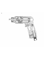
ARO DG051B-7-B is a pneumatic 50 series drill with a maximum operating air pressure of 90 p.s.i.g. that can be used for a variety of drilling applications. The tool features a durable housing, a powerful motor, and a comfortable trigger for easy operation. The ARO DG051B-7-B is ideal for drilling holes in metal, wood, and plastic. It is a versatile tool that can be used by both professionals and DIYers.
ARO DG051B-7-B is a pneumatic 50 series drill with a maximum operating air pressure of 90 p.s.i.g. that can be used for a variety of drilling applications. The tool features a durable housing, a powerful motor, and a comfortable trigger for easy operation. The ARO DG051B-7-B is ideal for drilling holes in metal, wood, and plastic. It is a versatile tool that can be used by both professionals and DIYers.


-
 1
1
-
 2
2
-
 3
3
-
 4
4
-
 5
5
-
 6
6
-
 7
7
-
 8
8


ARO DG051B-7-B is a pneumatic 50 series drill with a maximum operating air pressure of 90 p.s.i.g. that can be used for a variety of drilling applications. The tool features a durable housing, a powerful motor, and a comfortable trigger for easy operation. The ARO DG051B-7-B is ideal for drilling holes in metal, wood, and plastic. It is a versatile tool that can be used by both professionals and DIYers.
Ask a question and I''ll find the answer in the document
Finding information in a document is now easier with AI
Related papers


Other documents
-
Ingersoll-Rand 7742 User manual
-
Ingersoll-Rand 8488 User manual
-
-
-
-
-
Ingersoll-Rand 7848-E-EU Installation And Maintenance Information
-
-
-