Amana APC14H Owner's manual

Category
Split-system air conditioners
Type
Owner's manual

This manual is also suitable for

Goodman Company, L.P.
IOG-3009B 5151 San Felipe, Suite 500, Houston, TX 77056
02/2018 www.goodmanmfg.com or www.amana-hac.com
© 2010 - 2015, 2018 Goodmam Company, L.P.
I
NSTALLATION
I
NSTRUCTIONS
F
OR
S
ELF
-C
ONTAINED
P
ACKAGE
A
IR
C
ONDITIONERS
AND
H
EAT
P
UMP
U
NITS
*PC/*PH 14 SEER “H” SERIES
W
ITH
R-410A
RECOGNIZE THIS SYMBOL AS A SAFETY PRECAUTION.
All information contained herein is subject to change without notice.
*NOTE: Please contact your distributor or our
website for the applicable Specification
Sheets referred to in this manual.
These installation instructions cover the outdoor instal-
lation of self contained package air conditioner and heat-
ing units. See the Specification Sheets applicable to
your model for information regarding accessories.
is a registered trademark of Maytag Corporation or its related companies and is used under license All rights reserved.
O
NLY
PERSONNEL
THAT
HAVE
BEEN
TRAINED
TO
INSTALL
,
ADJUST
,
SERVICE
OR
REPAIR
(
HEREINAFTER
, “
SERVICE
”)
THE
EQUIPMENT
SPECIFIED
IN
THIS
MANUAL
SHOULD
SERVICE
THE
EQUIPMENT
. T
HE
MANUFACTURER
WILL
NOT
BE
RESPONSIBLE
FOR
ANY
INJURY
OR
PROPERTY
DAMAGE
ARISING
FROM
IMPROPER
SERVICE
OR
SERVICE
PROCEDURES
. I
F
YOU
SERVICE
THIS
UNIT
,
YOU
ASSUME
RESPONSIBILITY
FOR
ANY
INJURY
OR
PROPERTY
DAMAGE
WHICH
MAY
RESULT
. I
N
ADDITION
,
IN
JURISDICTIONS
THAT
REQUIRE
ONE
OR
MORE
LICENSES
TO
SERVICE
THE
EQUIPMENT
SPECIFIED
IN
THIS
MANUAL
,
ONLY
LICENSED
PERSONNEL
SHOULD
SERVICE
THE
EQUIPMENT
. I
MPROPER
INSTALLATION
,
ADJUSTMENT
,
SERVICING
OR
REPAIR
OF
THE
EQUIPMENT
SPECIFIED
IN
THIS
MANUAL
,
OR
ATTEMPTING
TO
INSTALL
,
ADJUST
,
SERVICE
OR
REPAIR
THE
EQUIPMENT
SPECIFIED
IN
THIS
MANUAL
WITHOUT
PROPER
TRAINING
MAY
RESULT
IN
PRODUCT
DAMAGE
,
PROPERTY
DAMAGE
,
PERSONAL
INJURY
OR
DEATH
.
2
TO THE INSTALLER........................................................2
SHIPPING INSPECTION ..............................................2
Checking Product Received.........................................2
Message to the Homeowner ........................................3
REPLACEMENT PARTS ...............................................3
Ordering Parts ................................................................3
IMPORTANT SAFETY INSTRUCTIONS .......................3
Recognize Safety Symbols, Words, and Labels.......3
CODES AND REGULATIONS .......................................3
General............................................................................3
EPA Regulations.............................................................4
National Codes ...............................................................4
MAJOR COMPONENTS ...............................................4
General............................................................................4
INSTALLATION ............................................................4
Pre-Installation Checkpoints ........................................4
Clearance........................................................................4
Location...........................................................................4
Outside Slab Installation (Figure 1) ............................4
Rooftop Installation (Figure 2) .....................................4
DUCTING......................................................................5
Connecting the Return and Supply Flexible Duct in
Manufactured or Modular Housing Application........5
Plenum Application.......................................................5
Filters ...............................................................................6
PIPING .........................................................................6
Condensate Drain ..........................................................6
WIRING ........................................................................6
High Voltage Wiring ......................................................6
Low Voltage Wiring.......................................................6
Internal Wiring: ..............................................................7
OPERATION .................................................................7
Start-Up Procedure and Checklist...............................7
Heat Pump Start-Up Procedure ...................................7
HEAT PUMP REFRIGERANT CIRCUIT - FIGURE 7......8
Final System Checks .....................................................8
COMPONENTS ................................................................8
Contactor.........................................................................8
Crankcase Heater ..........................................................8
Condenser Motor............................................................8
Compressor .....................................................................8
Contactor Relay..............................................................9
Defrost Control................................................................9
Outdoor Thermostat ......................................................9
Reversing Valve Coil .....................................................9
Indoor Blower Motor .....................................................9
Blower Interlock Relay .................................................9
EXPLANATION AND GUIDANCE (HEAT PUMP)...........9
DEFROST CONTROL ......................................................9
AIR FLOW MEASUREMENT AND ADJUSTMENT ......10
ADJUSTING SPEED TAP FOR INDOOR
BLOWER MOTOR .........................................................10
ELECTRIC HEAT INSTALLATION & ADJUSTMENT...11
MAINTENANCE ............................................................ 12
SERVICE ........................................................................12
Inadequate Air Volume Through Indoor Coil..........12
Outside Air Into Return Duct ......................................12
Undercharge.................................................................12
Poor “Terminating” Sensor Contact.........................12
Malfunctioning Reversing Valve................................12
BLOWER PERFORMANCE GP* 14 SEER ............ 13-14
TROUBLESHOOTING CHART......................................15
START-UP CHECKLIST ................................................18
TO T HE I NSTALLER
Carefully read all instructions for the installation prior to installing
unit. Make sure each step or procedure is understood and any
special considerations are taken into account before starting
installation. Assemble all tools, hardware and supplies needed
to complete the installation. Some items may need to be pur-
chased locally. After deciding where to install unit, closely look
the location over - both the inside and outside of home. Note any
potential obstacles or problems that might be encountered as
noted in this manual. Choose a more suitable location if nec-
essary.
IMPORTANT NOTE: If a crankcase heater is used, the unit
should be energized 24 hours prior to compressor start up to
ensure crankcase heater has sufficiently warmed the com-
pressor. Compressor damage may occur if this step is not
followed.
Before using this manual, check the serial plate for proper
model identification.
The installation and servicing of this equipment must be
performed by qualified, experienced technicians only.
SHIPPING INSPECTION
Checking Product Received
Upon receiving the unit, inspect it for damage from shipment.
Claims for damage, either shipping or concealed, should be
filed immediately with the shipping company. Check the unit
model number, specifications, electrical characteristics and
accessories to determine if they are correct. In the event an
incorrect unit is shipped, it must be returned to the supplier
and must NOT be installed. The manufacturer assumes no
responsibility for installation of incorrectly shipped units.
Message to the Homeowner
These instructions are addressed primarily to the installer;
however, useful maintenance information is included and
should be kept, after installation, for future reference.
3
REPLACEMENT PARTS
Ordering Parts
When reporting shortages or damages, or ordering repair parts,
give the complete unit model and serial numbers as stamped
on the unit’s nameplate. Replacement parts for this appliance
are available through your contractor or local distributor. For
the location of your nearest distributor, consult the white business
pages, the yellow page section of the local telephone book or
contact: CONSUMER AFFAIRS
GOODMAN MANUFACTURING COMPANY, L.P.
7401 SECURITY WAY
HOUSTON, TEXAS 77040
877-254-4729
IMPORTANT SAFETY INSTRUCTIONS
Recognize Safety Symbols, Words, and Labels
The following symbols and labels are used throughout this
manual to indicate immediate or potential hazards. It is the
owner’s responsibility to read and comply with all safety
information and instructions accompanying these symbols.
Failure to heed safety information increases the risk of serious
personal injury or death, property damage and/or product
damage.
WARNING
D
O NOT CONNECT TO OR USE ANY DEVICE THAT IS NOT DESIGN-CERTIFIED
BY
G
OODMAN FOR USE WITH THIS UNIT.
S
ERIOUS PROPERTY DAMAGE,
PERSONAL INJURY, REDUCED UNIT PERFORMANCE AND/
OR
HAZARDOUS
CONDITIONS MAY RESULT FROM THE USE OF SUCH NON-APPROVED DEVICES.
WARNING
HIGH
VOLTAGE
!
D
ISCONNECT
ALL
POWER BEFORE SERVICING OR INSTALLING
THIS UNIT.
M
ULTIPLE POWER SOURCES MAY BE PRESENT. FAILUR
TO DO SO MAY CAUSE PROPERTY DAMAGE, PERSONAL INJURY OR
DEATH.
E
WARNING
C
ONNECTING UNIT DUCT WORK TO UNAUTHORIZED HEAT PRODUCING DEVICES
SUCH AS A FIREPLACE INSERT, STOVE, ETC. MAY RESULT IN PROPERTY
DAMAGE, FIRE, CARBON MONOXIDE POISONING, EXPLOSION, PERSONAL
INJURY OR DEATH.
WARNING
T
HIS PRODUCT CONTAINS OR PRODUCES A CHEMICAL OR CHEMICALS WHICH
MAY CAUSE SERIOUS ILLNESS OR DEATH AND WHICH ARE KNOWN TO THE
S
TATE OF
C
ALIFORNIA TO CAUSE CANCER, BIRTH DEFECTS OR OTHER
REPRODUCTIVE HARM.
WARNING
T
O AVOID PROPERTY DAMAGE, PERSONAL INJURY OR DEATH, DO NOT USE
THIS UNIT IF ANY PART HAS BEEN UNDER WATER.
I
MMEDIATELY CALL A
QUALIFIED SERVICE TECHNICIAN TO INSPECT THE FURNACE AND TO REPLACE
ANY PART OF THE CONTROL SYSTEM AND ANY GAS CONTROL HA
V
ING BEEN
UNDER WATER.
WARNING
T
HIS UNIT MUST NOT BE USED AS A "CONSTRUCTION HEATER" DURING THE
FINISHING PHASES OF CONSTRUCTION ON A NEW STRUCTURE.
T
HIS TYPE OF
USE MAY RESULT IN PREMATURE FAILURE OF THE UNIT DUE TO EXTREMELY
LOW RETURN AIR TEMPERATURES AND EXPOSURE TO CORROSI
V
E OR
V
ERY
DIRTY ATMOSPHERES.
WARNING
T
O PREVENT THE RISK OF PROPERTY DAMAGE, PERSONAL INJURY, OR DEATH,
DO NOT STORE COMBUSTIBLE MATERIALS OR USE GASOLINE OR OTHER
FLAMMABLE LIQUIDS OR VAPORS IN THE VICINITY OF THIS APPLIANCE.
CODES AND REGULATIONS
General
The *PC & *PH series air conditioners and heat pumps are
designed for OUTDOOR USE ONLY. This series is available
in cooling Capacities of 2, 2 ½, 3, 3 ½, 4 and 5 nominal tons
of cooling. Optional field installed heat kits are available in
5,8,10,15 and 20 KW. The units can be easily installed in
manufactured or modular homes with existing high-static duct
work. The units can also be easily converted to accommo-
date a plenum for normal or low-static applications. The *PC
& *PH series are self contained packaged units so the only
connections needed for installation are the supply and return
ducts, the line and low voltage wiring and drain connection.
Rated performance is achieved after 20 hours of operation.
Rated performance is delivered at the specified airflow. See
outdoor unit specification sheet for split system models or prod-
uct specification sheet for packaged and light commercial mod-
els. Specification sheets can be found at www.goodmanmfg.com
for Goodman® brand products or www.amana-hac.com for
Amana® brand products. Within either website, please select
the residential or commercial products menu and then select
the submenu for the type of product to be installed, such as air
conditioners or heat pumps, to access a list of product pages
that each contain links to that model’s specification sheet.
The information on the rating plate is in compliance with the
FTC & DOE rating for single phase units. The three phase
units in this series are not covered under the DOE certified
program. The efficiency ratings of these units are a product
of thermal efficiency determined under continuous operating
conditions independent of any installed system.
EPA Regulations
4
as corners provide a minimum 10” clearance on all air inlet
sides. Allow 18” minimum for service access to the compressor
compartment and controls. The top of the unit should be
completely unobstructed. If units are to be located under an
overhang, there should be a minimum of 36” clearance and
provisions made to deflect the warm discharge air out from the
overhang.
Location
Consider the affect of outdoor fan noise on conditioned space
and any adjacent occupied space. It is recommended that
the unit be placed so that condenser air discharge does not
blow toward windows less than 25 feet away.
The unit should be set on a solid, level foundation - preferably
a concrete slab at least 4 inches thick. The slab should be
above ground level and surrounded by a graveled area for
good drainage. Any slab used as a unit’s foundation should
not adjoin the building as it is possible that sound and vibration
may be transmitted to the structure. For rooftop installation,
steel or treated wood beams should be used as unit support
for load distribution.
Heat pumps require special location consideration in areas
of heavy snow accumulation and/or areas with prolonged
continuous subfreezing temperatures. Heat pump unit bases
have holes under the outdoor coil to permit drainage of defrost
water accumulation. The unit must be situated to permit free
unobstructed drainage of the defrost water and ice. A
minimum 2" clearance under the outdoor coil is required in
the milder climates.
Outside Slab Installation (Figure 1)
1. The unit must be mounted on a solid, level foundation.
2. Select a location that will minimize the length of the supply
and return ducts.
3 Select a location where external water drainage cannot
collect around the unit.
4. Consideration should also be given to shade, appearance
and noise.
36"
36"
10"
UNIT
WALL
36"
FIGURE 1
Rooftop Installation (Figure 2)
1. Before locating the unit on the roof, make sure that the
strength of the roof and beams is adequate to support the
weight involved. (See specification sheet for weight of units.)
This is very important and the installer’s responsibility.
2. Make proper consideration for the weather–tight integrity of
the roof and proper drainage of condensate.
3. To ensure proper condensate drainage, unit must be
IMPORTANT: THE UNITED STATES ENVIRONMENTAL
PROTECTION AGENCY (EPA) HAS ISSUED VARIOUS
REGULATIONS REGARDING THE INTRODUCTION AND
DISPOSAL OF REFRIGERANTS IN THIS UNIT. FAILURE
TO FOLLOW THESE REGULATIONS MAY HARM THE
ENVIRONMENT AND CAN LEAD TO THE IMPOSITION
OF SUBSTANTIAL FINES. BECAUSE REGULATIONS
MAY VARY DUE TO PASSAGE OF NEW LAWS, WE
SUGGEST A CERTIFIED TECHNICIAN PERFORM ANY
WORK DONE ON THIS UNIT. SHOULD YOU HAVE ANY
QUESTIONS PLEASE CONTACT THE LOCAL OFFICE
OF THE EPA.
National Codes
This product is designed and manufactured to permit
installation in accordance with National Codes. It is the
installer’s responsibility to install the product in accordance
with National Codes and/or prevailing local codes and
regulations. MAJOR COMPONENTS
General
The unit includes a hermetically sealed refrigerating system
(consisting of a compressor, condenser coil, evaporator coil
with flowrator), an indoor blower, a condenser fan and all
necessary internal electrical wiring. The heat pump also
includes a reversing valve, solenoid, defrost thermostat and
control and loss of charge protection. The system is factory-
evacuated, charged and performance tested. Refrigerant
amount and type are indicated on rating plate.
INSTALLATION
Pre-Installation Checkpoints
Before attempting any installation, the following points
should be considered:
Structural strength of supporting members
Clearances and provision for servicing
Power supply and wiring
Air duct connections
Drain facilities and connections
• Location may be on any four sides of a home,
manufactured or modular, to minimize noise
Clearance
The unit is designed to be located outside the building with
unobstructed condenser air inlet and discharge.
Additionally, the unit must be situated to permit access for
service and installation. Condenser air enters from three
sides. Air discharges upward from the top of the unit.
Refrigerant gauge connections are made on the right side
of the unit as you face the compressor compartment.
Electrical connections can be made either on the right or
left sides of the unit. The best and most common application
is for the unit to be located 10” from wall (4” minimum) with
the connection side facing the wall. This “close to the wall”
application minimizes exposed wiring.
Close to the wall application assures free, unobstructed air to
the other two sides. In more confined application spaces, such
5
installed in a level position.
4. Consideration should also be given to shade, appearance and
noise.
36"
36"
24"
PLENUM
UNIT
PLATFORM
CURB
FIGURE 2
DUCTING
WARNING
D
O
NOT
,
UNDER
ANY
CIRCUMSTANCES
,
CONNECT
RETURN
DUCT
-
WORK
TO
ANY
OTHER
HEAT
PRODUCING
DEVICES
SUCH
AS
FIRE
-
PLACE
INSERT
,
STOVE
,
ETC
. U
NAUTHORIZED
USE
OF
SUCH
DEVICES
MAY
RESULT
IN
PROPERTY
DAMAGE
,
FIRE
,
CARBON
MONOXIDE
POISONING
,
EXPLOSION
,
PERSONAL
INJURY
OR
DEATH
.
Ducting work should be fabricated by the installing contractor
in accordance with local codes. Industry manuals may be
used as a guide when sizing and designing the duct system-
such as NESCA (National Environmental Systems
Contractors Association, 1501 Wilson Blvd., Arlington,
Virginia 22209).
The unit should be placed as close as possible to the space
to be air-conditioned allowing clearance dimensions as
indicated. Ducts should run as directly as possible to supply
and return outlets. Use of non-flammable weatherproof flexible
connectors on both supply and return connections at the
unit to reduce noise transmission is recommended.
It is preferable to install the unit on the roof of the structure if
the registers or diffusers are located in the wall or ceiling. A
slab installation is recommended when the registers are low
on the wall or in the floor.
Connecting the Return and Supply Flexible Duct in
Manufactured or Modular Housing Application
The return and supply fittings are to be attached at the unit
to a suitable square to round duct converter. Your distributor
has a factory designed square to round converter transition.
The model #’s of these kits are as follows: Small Chassis
25” SQRPCH101, Medium Chassis 27.5” SQRPCH102, Large
and Extra Large Chassis 32.5:” and 36” SQRPCH103 (See
Specification Sheets for Dimension details). The SQRPCH101
has 14" duct collar on supply and 16" duct collar (equivalent
diameter, opening is oval) on the return. The SQRPCH102 and
SQRPCH103 have 14" duct collar on supply and 18" duct collar
(equivalent diameter, opening is oval) on the return. The collars
are to be slipped into the openings, and the flanges bent around
the converter. The square to round converter is attached to the
flanges of the square duct openings. The flexible duct is then
clamped on to the collars. Once the duct is affixed to the unit,
seal the collars and flanges with a proper waterproof
sealant (See Figure 3).
It is strongly encouraged to use appropriately sized ducts based
upon the CFM for your application (unit’s CFM). If duct sizing
through industry manuals or air duct calculators require larger
ducts than converter openings, run larger duct size up to unit
converter openings and reduce with a reducer duct fitting or
transition right at the unit.
NOMINAL SIZE (INCHES) NOMINAL AREA (SQ. FT.)
10x20 1.4
14x20 1.9
14x25 2.4
15x20 2.1
16x20 2.2
16x25 2.8
20x20 2.8
20x25 3.5
25x25 4.3
MINIMUM FILTER SIZE
TABLE 1
OUTER FLANGE
STARTER FLANGE
SQUARE TO ROUND
DUCT CONVERTER PANEL
FIGURE 3
500 1000 1500 2000 2500 3000 3500
7
6
5
4
3
2
DISPOSABLE FILTER
PERMANENT FILTER
Airflow - SCFM
Nominal Filter Area
Square Feet
FIGURE 4
Plenum Application
A suitable plenum or square duct must be constructed. The
duct cross-sectional area should be determined by industry
duct sizing manuals or air duct calculators.
On ductwork exposed to outside air conditions of temperature
and humidity, use an insulation with a good K factor, and a
6
vapor barrier. Industry practices should be followed. Balancing
dampers are recommended for each branch duct in the supply
system. Ductwork should be properly supported from the unit.
NOTE: Proper sealing of all duct work and air handling
compartments is extremely important to overall unit
efficiency.
Filters
Filters are not provided with unit, and must be supplied and
installed in the return duct system by the installer. A field
installed filter grille is recommended for easy and convenient
access to the filters for periodic inspection and cleaning.
Filters must have adequate face area for the rated quantity
of the unit. See air delivery tables (Figure 4) for
recommended filter size. PIPING
Condensate Drain
The condensate drain connection of the evaporator is a half
coupling of ¾” N.P.T. A trap must be provided to have Proper
condensate drainage.
2" Minimum
3" Minimum
A
Positive Liquid Seal
Is Required
Flexible
Tubing-Hose
Or Pipe
Drain
Connection
Unit
FIGURE 5
Install condensate drain trap as shown. Use ¾ “ drain
connection size or larger. Do not operate without trap. Unit
must be level or slightly inclined toward drain.
WIRING
All wiring should be made in accordance with the
National Electrical Code. The local Power Company
should be consulted to determine the availability of sufficient
power to operate the unit. The voltage, frequency, and phase
at the power supply should be checked to make sure it
corresponds to the unit’s RATED VOLTAGE
REQUIREMENT.
Install a branch circuit fused disconnect near the unit, in
accordance with the N.E.C. or local codes. Wire sizes and
overcurrent protection should be determined from the unit
nameplate ampacity and in accordance with Table 4 (page
7) or the N.E.C. Under no circumstances should wiring be
sized smaller than is recommended by either of these two
sources.
Fuses smaller than that recommended on the wiring diagrams
could result in unnecessary fuse failure or service calls.
The use of protective devices of larger size than indicated could
result in extensive damage to the equipment. The manufacturer
bears no responsibility for damage caused to equipment as
result of the use of larger than is recommended size protective
devices.
All units have undergone a run test prior to packaging for
shipment. This equipment has been started at minimum rated
voltage and checked for satisfactory operation. Do not
attempt to operate this unit if the voltage is not within the
minimum and maximum voltages shown on nameplate.
All exterior wiring must be within approved weatherproof
conduit. The unit must be permanently grounded in
accordance with local codes, or in absence of local codes,
with N.E.C ANSI/ NFPA NO. 70-1984 or latest edition by
using ground lug in the control box.
Fuses or HACR type circuit breakers may be used where
codes permit.
CONTACTOR
RW
G
GRW
FOR INTERNAL WIRING SEE WIRING LABEL ATTACHED TO UNIT
24 VOLT CONTROL WIRING
FIGURE 6
Note: Some single phase units are equipped with a single
pole contactor. Caution must be exercised when servicing
as only one leg of the power supply is broken with the
contactor.
To wire the unit, make the following high and low voltage
connections.
WARNING
HIGH
VOLTAGE
!
D
ISCONNECT
ALL
POWER BEFORE SERVICING OR INSTALLING
THIS UNIT.
M
ULTIPLE POWER SOURCES MAY BE PRESENT. FAILU
TO DO SO MAY CAUSE PROPERTY DAMAGE, PERSONAL INJURY O
DEATH.
RE
R
High Voltage Wiring: (See Figure 6)
Single Phase- Two leads should be connected to terminals L1
& L2 in the electrical control section, using wire sizes specified
in wiring table.
Low Voltage Wiring: (See Figure 6)
a. Air Conditioners- Connect 24V wires from the thermostat to
the corresponding wires in the control box using No. 18AWG
as follows:
LEAD THERMOSTAT
Red R (24V)
Green G (Fan)
Yellow Y (Cool)
White W1 (Heat)*
Brown W2 (Heat)*
TABLE 2
b. Heat Pumps- Connect 24V wires from the thermostat to the
corresponding wires in the control box using No. 18AWG as
7
follows: TERMINAL THERMOSTAT
Red R (24V)
Green G (Fan)
Orange O (Rev. Valve)
White W1 (Heat, 2nd)*
Brown W2 (Heat 3rd)*
Yellow Y (Cool)
C (Blue) C (Common)
*Optional field installed heat connections
TABLE 3
Internal Wiring:
A diagram detailing the internal wiring of this unit is located on
the electrical box cover. If any of the original wire supplied with
the appliance must be replaced, the wire gauge and insulation
must be the same as the original wiring.
Transformer is wired for 230 volts on the 208/230 models. See
wiring diagram for 208 volt wiring.
BRANCH CIRCUIT AMPACITY 15 20 25 30 35 40 45 50
SUPPLY WIRE LENGTH -
FEET
200 64443322
150 86644433
100 108866644
50 141210108866
TABLE 4
1. For branch circuit wiring (main power supply to unit
disconnect), the minimum wire size for the length of the
run can be determined from Table 4 using the circuit
ampacity found on the unit rating plate. From the unit
disconnect to unit, the smallest wire size allowable in Table
4 may be used for the ampacity, as the Disconnect must
be in sight of the unit.
2. Wire size based on 60° C rated wire insulation and 30° C
Ambient Temperature (86° F).
3. For more than 3 conductors in a raceway or cable, see the
N.E.C. for derating the ampacity of each conductor.
OPERATION
Start-Up Procedure and Checklist
Begin with power turned off at all disconnects.
WARNING
HIGH
VOLTAGE
!
D
ISCONNECT
ALL
POWER BEFORE SERVICING OR INSTALLING
THIS UNIT.
M
ULTIPLE POWER SOURCES MAY BE PRESENT. FAILU
TO DO SO MAY CAUSE PROPERTY DAMAGE, PERSONAL INJURY O
DEATH.
RE
R
1. Turn thermostat system switch to “Cool,” and fan switch to
“Auto” and turn temperature setting as high as it will go.
2. Inspect all registers and set them to the normal open
position.
3. Turn on the electrical supply at the disconnect.
4. Turn the fan switch to the “ON” position. The blower should
operate after a 10 second delay.
5. Turn the fan switch to “Auto” position. The blower should stop
after a 60 second delay.
6. Slowly lower the cooling temperature until the unit starts. The
compressor, blower and fan should now be operating. Allow
the unit to run 10 minutes, make sure cool air is being supplied
by the unit.
7. Turn the temperature setting to the highest position, stopping
the unit. The indoor blower will continue to run for 60 seconds.
8. Turn the thermostat system switch to “OFF” and disconnect
all power when servicing the unit.
WARNING
HIGH
VOLTAGE
!
D
ISCONNECT
ALL
POWER BEFORE SERVICING OR INSTALLING
THIS UNIT.
M
ULTIPLE POWER SOURCES MAY BE PRESENT. FAILU
TO DO SO MAY CAUSE PROPERTY DAMAGE, PERSONAL INJURY O
DEATH.
RE
R
Heat Pump Start-Up Procedure
9. Check the cooling mode for the heat pump in the same
manner as above. The reversing valve is energized when
the thermostat is placed in the cooling position. A clicking
sound should be noticeable from the reversing valve. By
lowering the temperature setting to call for cooling, the
contractor is energized. The compressor, blower and fan
should then be running. After the cooling mode is checked
out, turn the thermostat system switch to “OFF”.
10. Turn the thermostat system switch to “HEAT” and fan switch
to “AUTO”.
11. Slowly raise the heating temperature setting. When the
heating first stage makes contact, stop raising the
temperature setting.. The compressor, blower and fan
should now be running with the reversing valve in the de-
energized (heating) position. After giving the unit time to
settle out, make sure the unit is supplying heated air.
12. If the out door ambient is above 80°F, the unit may trip on
its high pressure cut out when on heating. The compressor
should stop. The heating cycle must be thoroughly
checked, so postpone the test to another day when
conditions are more suitable but-DO NOT FAIL TO TEST.
If the out door ambient is low and the unit operates properly
on the heating cycle, you may check the pressure cutout
operation by blocking off the indoor return air until the unit
trips.
13. If unit operates properly in the heating cycle, raise the
temperature setting until the heating second stage makes
contact. Supplemental resistance heat, if installed should
now come on. Make sure it operates properly.
NOTE: If outdoor thermostats are installed the outdoor
ambient must be below the set point of these thermostats
for the heaters to operate. It may be necessary to jumper
these thermostats to check heater operation if outdoor
ambient is mild.
14. For thermostats with emergency heat switch, return to step
11. The emergency heat switch is located at the bottom of
the thermostat. Move the switch to emergency heat. The
heat pump will stop, the blower will continue to run, all
heaters will come on and the thermostat emergency heat
light will come on.
15. If checking the unit in the wintertime, when the outdoor coil is
cold enough to actuate the defrost control, observe at least
one defrost cycle to make sure the unit defrosts completely.
8
Final System Checks
16. Check to see if all supply and return air grilles are adjusted
and the air distribution system is balanced for the best
compromise between heating and cooling.
17. Check for air leaks in the ductwork.
18. See Sections on Air Flow Measurement and Adjustment
and Checking Charge.
19. Make sure the unit is free of “rattles”, and the tubing in the
unit is free from excessive vibration. Also make sure tubes
or lines are not rubbing against each other or sheet metal
surfaces or edges. If so, correct the trouble.
20. Set the thermostat at the appropriate setting for cooling
and heating or automatic changeover for normal use.
21. Be sure the Owner is instructed on the unit operation, filter,
servicing, correct thermostat operation, etc.
The foregoing “Start-up Procedure and Check List” is
recommended to serve as an indication that the unit will
operate normally.
COMPONENTS
1. Contactor - This control is activated (closed) by the room
thermostat for both heating and cooling. The contactor has
a 24V coil and supplies power to the compressor and
outdoor fan motor.
2. Crankcase Heater – This item is “ON” whenever power is
supplied to the unit and the crankcase heater thermostat
is closed. Crankcase heater thermostat closes at 67° and
opens at 85°. It warms the compressor crankcase thereby
preventing liquid migration and subsequent compressor
damage. The insert type heater is self regulating. It is
connected electrically to the contactor L1 and L2 terminals.
3. Condenser Motor - This item is activated by the contactor
during heating and cooling, except during defrost and
emergency heat operation.
4. Compressor - This item is activated by the contactor for
heating and cooling, except during emergency heat. It is
protected by an internal overload.
5. Contactor Relay - This control is activated by the thermostat
(24V coil) and supplies power to the contactor.
EVAPORATOR
COOLING
SERVICE VALVE
SERVICE PORT REVERSING VALVE
CONDENSER
SERVICE PORT
COMPRESSOR
SERVICE PORT
ACCUMULATOR
EXPANSION DEVICE
CHECK VALVE
ORIFICE
SERVICE
VALVE
CHECK VALVE
ORIFICE
INDOOR
COIL
DISTRIBUTOR
OUTDOOR
COIL
EVAPORATOR
HEATING
SERVICE VALVE
SERVICE PORT REVERSING VALVE
CONDENSER
COMPRESSOR
SERVICE PORT
ACCUMULATOR
CHECK VALVE
ORIFICE
SERVICE
VALVE
CHECK VALVE
ORIFICE
INDOOR
COIL
DISTRIBUTOR
OUTDOOR
COIL
DISTRIBUTOR
HEAT PUMP REFRIGERANT CIRCUIT - FIGURE 7
9
6. Defrost Control - The Defrost control provides time/
temperature initiation and termination of the defrost cycle.
When a Defrost cycle is initiated, the defrost control shifts
the reversing valve to “cooling” mode, stops the outdoor
fan and brings on supplemental heat. Normally, a Defrost
cycle will take only 2-3 minutes unless system is low on
charge or outdoor conditions are severe. (Windy and cold.)
The defrost control also provides for a 3 minute off cycle
compressor delay.
7. Outdoor Thermostat - These optional controls are used to
prevent full electric heater operation at varying outdoor
ambient (0° F-to 45° F). They are normally open above their
set points and closed below to permit staging of indoor
supplement heater operation. If the outdoor ambient
temperature is below 0° F (-18° C) with 50% or higher RH,
an outdoor thermostat (OT) must be installed and set at
(0°) on the dial. Failure to comply with this requirement
may result in damage to the product which may not be
covered by the manufacturer’s warranty.
8. Reversing Valve Coil - This coil is activated by the
thermostat, in the cooling mode and during defrost. It
positions the reversing valve pilot valve for cooling
operation.
9. Indoor Blower Motor
Units with EEM Motors The EEM model indoor blower motor
is activated by the room thermostat by COOLING/HEATING
or FAN ON position. The motor is energized by a 24 volt
control signal (from thermostat Y, G or W) for EEM motors.
EEM motors are constant torque motors with very low power
consumption.
(See Air Flow Measurement and Adjustment for speed
adjustment instructions).
10. Blower Interlock Relay - This relay is used to energize the
blower during the electric heat operation. Some room
thermostats do not energize the motor during electric heat.
This relay insures blower operation when the room
thermostat energizes heat. This relay has a 240 volt coil
and an 8 amp contact relay. This relay is energized by the
electric heat kit sequencer.
EXPLANATION AND GUIDANCE (HEAT PUMP)
The heat pump is a relatively simple device. It operates exactly
as a Summer Air Conditioner unit when it is on the cooling
cycle. Therefore, all the charts and data for service that apply
to summer air conditioning apply to the heat pump when it
is on the cooling cycle, and most apply on the heating cycle
except that “condenser” becomes “evaporator”, “evaporator”
becomes “condenser”, “cooling” becomes “heating”.
When the heat pump is on the heating cycle, it is necessary
to redirect the refrigerant flow through the refrigerant circuit
external to the compressor. This is accomplished with a
reversing valve. Thus, the hot discharge vapor from the
compressor is directed to the indoor coil (evaporator on the
cooling cycle) where the heat is removed, and the vapor
condenses to liquid. It then goes through the expansion
device to the outdoor coil (condenser on the cooling cycle)
where the liquid is evaporated, and the vapor goes to the
compressor.
When the solenoid valve coil is operated either from heating to
cooling or vice versa, the piston in the reversing valve to the
low pressure (high pressure) reverse positions in the reversing
valve.
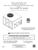
Figure 7 shows a schematic of a heat pump on the cooling
cycle and the heating cycle. In addition to a reversing valve,
a heat pump is equipped with an expansion device and check
valve for the indoor coil, and similar equipment for the outdoor
coil. It is also provided with a defrost control system.
The expansion devices are flowrator distributors and perform
the same function on the heating cycle as on the cooling
cycle. The flowrator distributors also act as check valves
to allow for the reverse of refrigerant flow.
When the heat pump is on the heating cycle, the outdoor
coil is functioning as an evaporator. The temperature of the
refrigerant in the outdoor coil must be below the temperature
of the outdoor air in order to extract heat from the air. Thus,
the greater the difference in the outdoor temperature and
the outdoor coil temperature, the greater the heating capacity
of the heat pump. This phenomenon is a characteristic of a
heat pump. It is a good practice to provide supplementary
heat for all heat pump installations in areas where the
temperature drops below 45° F. It is also a good practice to
provide sufficient supplementary heat to handle the entire
heating requirement should there be a component failure of
the heat pump, such as a compressor, or refrigerant leak,
etc.
Since the temperature of the liquid refrigerant in the outdoor
coil on the heating cycle is generally below freezing point,
frost forms on the surfaces of the outdoor coil under certain
weather conditions of temperature and relative humidity.
Therefore, it is necessary to reverse the flow of the refrigerant
to provide hot gas in the outdoor coil to melt the frost
accumulation. This is accomplished by reversing the heat
pump to the cooling cycle. At the same time, the outdoor
fan stops to hasten the temperature rise of the outdoor coil
and lessen the time required for defrosting. The indoor blower
continues to run and the supplementary heaters are
energized. DEFROST CONTROL
During operation the power to the circuit board is controlled
by a temperature sensor, which is clamped to a feeder tube
entering the outdoor coil. Defrost timing periods of 30,60
and 90 minutes may be selected by setting the circuit board
jumper to 30, 60 and 90 respectively. Accumulation of time
for the timing period selected starts when the sensor closes
(approximately 34 + 5° F), and when the wall thermostat
calls for heat. At the end of the timing period, the unit’s
defrost cycle will be initiated provided the sensor remains
closed. When the sensor opens (approximately 60° F), the
defrost cycle is terminated and the timing period is reset. If
the defrost cycle is not terminated due to the sensor
temperature, a twelve minute override interrupts the unit’s
defrost period.
10
SUGGESTED FIELD TESTING/TROUBLE SHOOTING
1. Run unit in the heating mode (room thermostat calling for heat).
2. Check unit for proper charge. Note: Bands of frost on the
condenser coil indicate low refrigerant charge.
3. Shut off power to unit.
4. Disconnect outdoor fan by removing the outdoor fan motor
wire from “DF2” on defrost control.
5. Restart unit and allow frost to accumulate.
6. After a few minutes of operation, the unit’s defrost thermostat
should close. To verify this, check for 24 volts between “DFT”
and “C” on board. If the temperature at the thermostat is
less than 28° F and the thermostat is open, replace the
unit’s defrost thermostat, as it is defective.
7. When the unit’s defrost thermostat has closed, short the
test pins on the defrost board until the reversing valve shifts,
indicating defrost. This should take up to 22 seconds
depending on what timing period the control is set on. After
defrost initiation, the short must instantly be removed or the
unit’s defrost period will only last 3 seconds.
8. The control is shipped from the factory with the compressor
delay option selected. This will de-energize the compressor
contactor for 30 seconds on defrost initiation and defrost
termination. If the jumper is set to Normal, the compressor
will continue to run during defrost initiation and defrost
termination. The control will also ignore the low pressure
switch connected to R-PS1 and PS2 for 5 minutes upon
defrost initiation and 5 minutes after defrost termination.
9. After the unit’s defrost thermostat has terminated, check
the defrost thermostat for 24 volts between “DFT” and “C”.
The reading should indicate 0 volts (open sensor).
10. Shut off power to unit.
11. Replace outdoor fan motor lead to terminal “DF2” on defrost
board and turn on power.
AIR FLOW MEASUREMENT AND ADJUSTMENT
After reviewing section on DUCTING, proceed with airflow
measurements and adjustments. Unit’s blower curves (in
Specification Sheets) are based on external static pressure
(ESP, in. of W.C.). The duct openings on the unit are considered
internal static pressure, so as long as ESP is maintained,
the unit will deliver the proper air up to the maximum static
pressure listed for the CFM required by the application (i.e.
home, building, etc.).
In general 400 CFM per ton of cooling capacity is a rule of
thumb. Some applications depending on the sensible and
latent capacity requirements may need only 350 CFM or up
to 425 CFM per ton. Check condition space load
requirements (from load calculations) and equipment
expanded ratings data to match CFM and capacity.
After unit is set and ducted, verify ESP with a 1" inclined
manometer with pitot tubes or a Magnahelic gauge and confirm
CFM to blower curves in the specification sheets. All units have
multiple speed blower motors. If factory selected speed is not
utilized, the speed tap can be changed. Never run CFM below
350 CFM per ton, evaporator freezing or poor unit performance
is possible.
ADJUSTING SPEED TAP
FOR INDOOR BLOWER MOTOR
EEM Motor
The blower motor speed for the EEM motor is controlled by
three 24V low voltage leads: green, yellow, and white. The
green lead sets the speed for fan-only mode. The yellow lead
sets the speed for cooling and heat pump heating mode (if
applicable). The white lead sets the speed for electric heat
mode (emergency heat and second stage heat, if applicable).
The leads are factory connected as follows: Green to T1,
Yellow to T2, and White to T3. T1 is the low speed setting
and is dedicated to fan-only mode. T2 is medium speed
cooling and T3 is medium speed heating. T4 is high speed
cooling and T5 is high speed heating. To adjust the blower
speed, move the yellow and/or white wires to T4 and T5.
NOTE: If more than one lead is energized at the same
time, the motor will use the higher speed setting.
NOTE: *PC14 and *PH14 units are rated for a maximum
E.S.P. of 0.8 except when using a 20kw electric heater.
(The maximum static for 20 kW electric heat is 0.5 E.S.P.)
When these units are installed in the 0.5 - 0.8 E.S.P. range,
the white lead (electric heat) must be moved to T5 for proper
operation of the electric heaters.
See CFM vs ESP tables in this manual.
Refrigerant Charge Check (Units with Fixed Orifice Devices)
After completing airflow measurements and adjustments the
unit’s refrigerant charge must be checked. All package units
with fixed orifice devices are charged using the super heat
method at the compressor suction line. After superheat is
adjusted it is recommended to check unit sub-cooling at the
condenser coil liquid line out. For charge adjustments, see
superheat and subcooling charts shown for each model.
SUPERHEAT CAN BE DETERMINED AS FOLLOWS:
1. Read suction pressure. Determine Saturated Suction Tem-
perature from tables or pressure gauge saturated tempera-
ture scale (R-410A).
2. Read suction line temperature.
3. Use the following formula:
SUPERHEAT = SUCTION LINE TEMP - SAT. SUCTION TEMP.
11
SUCTION
PRESSURE
SATURATED
SUCTION
TEMPERATURE
ºF
LIQUID
PRESSURE
SATURATED
LIQUID
TEMPERATURE
ºF
PSIG R-410A PSIG R-410A
50 1 200 70
52 3 210 73
54 4 220 76
56 6 225 78
58 7 235 80
60 8 245 83
62 10 255 85
64 11 265 88
66 13 275 90
68 14 285 92
70 15 295 95
72 16 305 97
74 17 325 101
76 19 355 108
78 20 375 112
80 21 405 118
85 24 415 119
90 26 425 121
95 29 435 123
100 31 445 125
110 36 475 130
120 41 500 134
130 45 525 138
140 49 550 142
150 53 575 145
160 56 600 149
170 60 625 152
SATURATED
SUCTION PRESSURE
TEMPERATURE CHART
SATURATED
LIQUID PRESSURE
TEMPERATURE CHART
TABLE 5
Suction Pressure Liquid Pressure
Temperature (R-410A) Temperature (R-410A)
SUBCOOLING = SAT. LINE TEMP - LIQUID LINE TEMP.
Models # Superheat ± 2°F
*PC1424H41 10
*PC1430H41 10
*PC1436H41 6
*PC1442H41 7
*PC1448H41 12
*PC1460H41 6
*PC
Design superheat @ 95 °F outdoor
ambient temperature
Models # Superheat ± 2°F
GPH1424H41 5
GPH1430H41 5
GPH1436H41 6
GPH1442H41 7
GPH1448H41 7
GPH1460H41 8
Design superheat @ 95 °F outdoor
ambient temperature
*PH
ELECTRIC HEAT INSTALLATION & ADJUSTMENT
This series of electric cooling and heat pump package
equipment is designed to accept a field installed electric heat
kit. The unit is equipped to easily install the HKR/HKP Series
Electric Heat Kit. Full Installation Instructions are included in this
kit. Please use this document for guidance in field equipping
the package unit with electric heat.
Choose the heat kit that fits the application for the specific
installation. Permanently mark the unit’s nameplate with the
model being installed. High and low voltage connections are
detailed in the heat kit instructions.
Indoor Blower motor speed tap selection may need to be
modified to accommodate normal continuous operation to
prevent a nuisance trip. See following table.
12
5 8 10 15 20
T3 T3*PC/*PH1460H41** T3 T3 T3
T3 T3
*PC/*PH1442H41** T3
*PC/*PH1448H41** T3 T3 T3
T3 T3
T5 NA
T5 NA
T3 T5
*PC/*PH1436H41** T3 T3 T3
*PC/*PH1430H41** T3 T3 T3
*PC/*PH1424H41** T3 T3 T3 T5 NA
*PC/*PH14(24-60) Models (0 - 0.5 E.S.P.)
Unit Model Number Electric Heat KW
5 8 10 15 20
*PC/*PH1424H41** T5 T5 T5 T5 NA
*PC/*PH1430H41** T5 T5 T5 T5 NA
*PC/*PH1436H41** T5 T5 T5 T5 NA
*PC/*PH1442H41** T5 T5 T5 T5 NA
*PC/*PH1448H41** T5 T5 T5 T5 NA
*PC/*PH1460H41** T5 T5 T5 T5 NA
T4 - High Speed Cooling; T5 - High Speed Heating
*PC/*PH14(24-60) MODELS ( 0.5 - 0.8 E.S.P.)
UNIT
MODEL NUMBER Electric Heat KW
T1 - Fan Only; T2 - Normal Speed Cooling
T3 - Normal Speed Heating
MAINTENANCE
WARNING
HIGH
VOLTAGE
!
D
ISCONNECT
ALL
POWER BEFORE SERVICING OR INSTALLING
THIS UNIT.
M
ULTIPLE POWER SOURCES MAY BE PRESENT. FAILU
TO DO SO MAY CAUSE PROPERTY DAMAGE, PERSONAL INJURY O
DEATH.
RE
R
The Self Contained Package Air Conditioner and Heat Pump
should operate for many years without excessive service calls
if the unit is installed properly. However it is recommended
that the homeowner inspect the unit before a seasonal start
up. The coils should be free of debris so adequate airflow is
achieved. The return and supply registers should be free of
any obstructions. The filters should be cleaned or replaced.
These few steps will help to keep the product up time to a
maximum. The Troubleshooting Chart (on page 16) should
help in identifying problems if the unit does not operate
properly.
SERVICE
THE FOLLOWING INFORMATION IS FOR USE BY QUALIFIED
SERVICE AGENCY ONLY: OTHERS SHOULD NOT ATTEMPT
TO SERVICE THIS EQUIPMENT.
Common Causes of Unsatisfactory Operation of Heat Pump
on the Heating Cycle.
Inadequate Air Volume Through Indoor Coil
When a heat pump is in the heating cycle, the indoor coil is
functioning as a condenser. The return air filter must always
be clean, and sufficient air volume must pass through the
indoor coil to prevent excessive discharge pressure, and high
pressure cut out.
Outside Air Into Return Duct
Do not introduce cold outside air into the return duct of a
heat pump installation. Do not allow air entering the indoor
coil to drop below 65° F. Air below this temperature will
cause low discharge pressure, thus low suction pressure,
and excessive defrost cycling resulting in low heating output.
It may also cause false defrosting.
Undercharge
An undercharged heat pump on the heating cycle will
cause low discharge pressure resulting in low suction
pressure and frost accumulation on the outdoor coil.
Poor “Terminating” Sensor Contact
The unit’s defrost terminating sensor must make good
thermal contact with the outdoor coil tubing. Poor contact
may not terminate the unit’s defrost cycle quickly enough to
prevent the unit from cutting out on high discharge pressure.
Malfunctioning Reversing Valve
This may be due to:
1. Solenoid not energized - In order to determine if the solenoid
is energized, touch the nut that holds the solenoid cover in
place with a screwdriver. If the nut magnetically holds the
screwdriver, the solenoid is energized and the unit is in the
cooling cycle.
2. No voltage at unit’s solenoid - Check unit voltage. If no
voltage, check wiring circuit.
3. Valve will not shift:
a. Undercharged - check for leaks;
b. Valve Body Damaged - Replace valve;
c. Unit Properly Charged - If it is on the heating cycle,
raise the discharge pressure by restricting airflow through
the indoor coil. If the valve does not shift, tap it lightly
on both ends with a screwdriver handle. Do Not Tap
The Valve Body. If the unit is on the cooling cycle,
raise the discharge pressure by restricting airflow through
the outdoor coil. If the valve does not shift after the above
attempts, cut the unit off and wait until the discharge
and suction pressure equalize, and repeat above steps.
If the valve does not shift, replace it.
13
*PC/*PH14[24-36]H41 BLOWER PERFORMANCE
NOTES:
1. Data shown is dry coil. Wet coil pressure drop is approx.
2. Data shown does not include filter pressure drop, approx. 0.08 H2O.
3. Reduce airflow by 2% for 208V operation.
0.1 0.2 0.3 0.4 0.5 0.6 0.7 0.8
CFM 922 873 823 774 724 675 626 576
Watts 74 85 96 107 118 129 140 151
CFM 922 873 823 774 724 675 626 576
Watts 74 85 96 107 118 129 140 151
CFM 1231 1179 1127 1074 1022 969 917 865
Watts 168 180 193 205 218 230 243 255
CFM 914 866 818 770 722 674 626 578
Watts 69 80 91 102 114 125 136 147
CFM 914 866 818 770 722 674 626 578
Watts 69 80 91 102 114 125 136 147
CFM 1231 1179 1127 1074 1022 969 917 865
Watts 168 180 193 205 218 230 243 255
CFM 1048 993 939 884 829 775 720 666
Watts 97 109 122 134 147 159 172 184
CFM 1123 1068 1014 959 905 850 796 741
Watts 123 136 148 161 173 186 198 211
CFM 1462 1409 1357 1305 1252 1200 1147 1095
Watts 241 253 266 278 291 303 315 328
CFM 1005 961 918 874 831 787 744 700
Watts 91 102 114 125 137 149 160 172
CFM 1110 1067 1023 980 936 893 849 806
Watts 120 132 144 155 167 178 190 202
CFM 1462 1409 1357 1305 1252 1200 1147 1095
Watts 241 253 266 278 291 303 315 328
CFM 1151 1097 1042 988 933 879 824 770
Watts 132 144 156 169 181 194 206 219
CFM 1261 1215 1169 1123 1076 1030 984 937
Watts 131 144 157 169 182 194 207 220
CFM 1577 1525 1472 1420 1367 1315 1263 1210
Watts 277 290 302 314 327 339 352 364
CFM 864 808 757 695 636 567 494 437
Watts 72 82 91 103 107 115 123 131
CFM 1107 1051 1008 960 907 854 807 749
Watts 127 137 151 156 165 177 182 193
CFM 1404 1362 1321 1271 1238 1191 1150 1105
Watts 235 246 257 272 284 289 300 309
*PC / *PH14[24-36]H41 BLOWER PERFORMANCE
Model Speed Volts E.S.P. (In. of H2O)
*PC1424H41**
T1 230
T2 / T3 230
T4 / T5 230
*PH1424H41**
T1 230
T2 / T3 230
T4 / T5 230
*PC1430H41**
T1 230
T2 / T3 230
T4 / T5 230
*PH1430H41**
T1 230
T2 / T3 230
T4 / T5 230
*PC1436H41**
*PH1436H41**
T1 230
T2 / T3 230
T4 / T5 230
*PC1430H41 E*
T1 230
T2 / T3 230
T4 / T5 230
14
*PC/*PH14[42-60]**H41 BLOWER PERFORMANCE
NOTES:
1. Data shown is dry coil. Wet coil pressure drop is approx.
2. Data shown does not include filter pressure drop, approx. 0.08” H2O.
3. Reduce airflow by 2% for 208V operation.
0.10.20.30.40.50.60.70.8
CFM 1165 1122 1080 1037 995 953 910 868
Watts 118 130 142 154 166 178 190 202
CFM 1258 1216 1173 1131 1088 1046 1004 961
Watts 150 162 175 187 199 211 223 235
CFM 1645 1602 1560 1517 1475 1433 1390 1348
Watts 285 297 309 321 333 346 358 370
CFM 1165 1122 1080 1037 995 953 910 868
Watts 118 130 142 154 166 178 190 202
CFM 1365 1322 1280 1237 1195 1153 1110 1068
Watts 188 200 212 224 236 248 260 272
CFM 1645 1602 1560 1517 1475 1433 1390 1348
Watts 285 297 309 321 333 346 358 370
CFM 1421 1367 1314 1260 1206 1152 1099 1045
Watts 170 182 195 208 220 233 246 258
CFM 1696 1643 1589 1535 1481 1428 1374 1320
Watts 287 299 312 325 337 350 363 375
CFM 1983 1928 1873 1818 1763 1708 1652 1597
Watts 553 565 578 591 603 616 629 641
CFM 1507 1459 1410 1362 1314 1266 1218 1169
Watts 168 175 183 191 199 207 214 222
CFM 1694 1646 1598 1549 1501 1453 1405 1357
Watts 296 303 311 319 327 334 342 350
CFM 1919 1870 1822 1774 1726 1678 1629 1581
Watts 449 457 465 472 480 488 496 503
CFM 1507 1459 1410 1362 1314 1266 1218 1169
Watts 168 175 183 191 199 207 214 222
CFM 1793 1745 1697 1649 1600 1552 1504 1456
Watts 363 371 379 387 394 402 410 418
CFM 1919 1870 1822 1774 1726 1678 1629 1581
Watts 449 457 465 472 480 488 496 503
CFM 1181 1146 1112 1062 1022 977 937 891
Watts 146 158 174 182 196 208 218 227
CFM 1410 1366 1328 1286 1248 1195 1155 1115
Watts 222 236 250 260 273 285 296 305
CFM 1637 1605 1561 1527 1484 1436 1390 1345
Watts 331 348 361 374 385 392 407 417
CFM 1337 1297 1218 1155 1118 1088 1022 989
Watts 179 190 203 210 225 243 249 268
CFM 1711 1640 1605 1537 1496 1441 1397 1347
Watts 330 341 358 370 377 394 408 418
CFM 2002 1935 1885 1827 1767 1732 1669 1618
Watts 498 521 516 534 551 567 571 574
Model Speed Volts E.S.P. (In. of H2O)
*PC1442H41**
T1 230
T2 / T3 230
T4 / T5 230
*PH1442H41**
T1 230
T2 / T3 230
T4 / T5 230
*PC1448H41**
*PH1448H41**
T1 230
T2 / T3 230
T4 / T5 230
*PC1460H41**
T1 230
T2 / T3 230
T4 / T5 230
*PH1460H41**
T1 230
T2 / T3 230
T4 / T5 230
*PC1442H41 E*
T1
T2/T3
T4/T5
230
230
230
*PC1448H41 E*
*PH1448H41 E*
T1 230
T2/T3 230
T4/T5 230
15
TROUBLESHOOTING CHART
WARNING
HIGH VOLTAGE!
D
ISCONNECT
ALL
POWER
BEFORE
SERVICING
OR
INSTALLING
THIS
UNIT
. M
ULTIPLE
POWER
SOURCES
MAY
BE
PRESENT
. F
AILURE
TO
DO
SO
MAY
CAUSE
PROPERTY
DAMAGE
,
PERSONAL
INJURY
OR
DEATH
.
SYMPTOM
High head - low suction a. Restriction in liquid line or flowrator a. Remove or replace with proper size flowrator.
High head - high or normal suction a. Dirty condenser coil a. Clean coil
b. Overchar
g
ed b. Correct S
y
stem char
g
e
c. Condenser fan not running c. Repair or Replace
a. Incorrect flowrato
r
a. Re
p
lace with correct flowrator
b. Defective com
p
ressor valves b. Re
lace com
ressor
c. Flowrator not seating properly c. Check for debris under flowrator or deformed
flowrator. Remove debris or replace flowrator.
a. Power off or loose electrical connection a. Check for unit voltage at contactor in unit
b. Thermostat out of calibration set too hi
g
hb.Reset
c. Defective contactor c. Check for 24 volts at contactor coil replace if
contacts are open
d. Blown fuses or tripped breaker d. Replace fuse or reset breaker Check wiring -
replace transformer
e. Transformer defective
f. High or low pressure control open
(Optional) f. Reset high pressure control or check unit charge
High pressure control opens at 610 psig
Low
p
ressure control o
p
ens at 22
p
si
g
g. Compressor overload contacts open g. Replace compressor
NOTE: Wait at least 2 hours for overload to
reset
Condenser fan runs,
compressor doesn't a. Loose connection a. Check for unit voltage at compressor check &
tighten all connections
b. Compressor stuck, grounded or open
winding open internal overload b. Wait at least 2 hours for overload to reset If still
open, replace the compressor.
c. Low voltage connection c. At compressor terminals, voltage must be within
10 % of nameplate volts when unit is operating
d. Capacitor weak, open, or shorted d. Check capacitor. If defective, replace.
Low suction - cool compressor a. a.
Iced evaporator coil a. Defective overload protector a. Replace - check for correct voltage
b. Unit cycling on low pressure control b. Check refrigerant charge and / or airflow
c. High pressure switch cuts out c. Check airflow (Indoor & outdoor)
a. a. Increase speed of blower or reduce restriction
replace air filters
a. Excessive load a. Recheck load calculation
b. Defective com
p
ressor b. Re
p
lace
c. Reversin
g
valve not seatin
g
p
ro
p
erl
y
.c.Re
p
lace
a. Im
p
ro
p
erl
y
sized unit a. Recalculate load
b. Improper airflow b. Check - should be approximately 400 CFM per ton
c. Incorrect refrigerant charge. c. Charge per procedure attached to unit service
panel
d. Incorrect voltage d. At compressor terminals, voltage must be within
10% of nameplate volts when unit is
operating
Evaporator coil freezing or frosting a. Low airflow a. Check - should be approximately 400 CFM per
ton, dirty air filters, all duct outlets open
b. Low refrigerant charge b. Properly charge unit
c. Operating unit in cooling mode below 65°F
outdoor temperature c. Install or check low ambient control, should be
open below 65°F outdoor temperature
Low indoor airflow Increase speed of blower or reduce restriction -
replace air filters
Insufficient cooling
High suction pressure
REMEDYPOSSIBLE CAUSE
Compressor short cycles
Registers sweat Low airflow
Low head - high suction
Unit will not run
16
PACKAGE UNITS - HEAT PUMP AND AC UNITS
HOMEOWNER’S ROUTINE MAINTENANCE RECOMMENDATIONS
aluminum tube residential cooling coils.
An alternate cleaning method is to use one of the products
listed in the technical publication TP-109 (shipped in the
literature bag with the unit) to clean the coils. The clean-
ers listed are the only agents deemed safe and approved for
use to clean round tube aluminum coils. TP-109 is available
on the web site in Partner Link > Service Toolkit.
NOTE: Ensure coils are rinsed well after use of any chemi-
cal cleaners.
ANNUAL INSPECTION (QUALIFIED SERVICER ONLY)
Your package unit should be inspected by a qualified in-
staller, or service agency at least twice every year. This
check should be performed before the heating and cooling
seasons begin. This will ensure that the system is perform-
ing properly and safely. Repair as necessary.
Check physical support of the unit. Ensure it is sound
without any sagging, cracks, or gaps, around the base.
Check for obvious signs of deterioration of the unit.
Check both condenser and evaporator coil to make sure
each are clean.
Return Air Connection. Check for physical soundness
and ensure that the connection is firmly sealed to the
package unit casing.
Wiring. Check wires for damage. Check electrical
connections for tightness and/or corrosion.
Filters. Check that filters are clean and in the proper
placement in the unit or duct system.
Louvers. Inspect air inlet louvers inside the heat
exchanger compartments. Ensure the area is clean and
free of dirt and debris.
BEFORE CALLING YOUR SERVICER
Check the thermostat to confirm that it is properly set.
Check the disconnect switch near the unit to confirm
that it is closed.
Check the electrical panel for tripped circuit breakers
or failed fuses . Reset the circuit breakers or replace
fuses as necessary.
Check for blockage of the indoor air inlets and outlets.
Confirm that they are open and have not been blocked by
objects (rugs, curtains or furniture).
Check for obstructions on the unit . Confirm that it has
not been covered on the sides or the top. Remove any
obstruction that can be safely removed. If the unit is
covered with dirt or debris, call a qualified servicer to clean
it.
Check the filter. If it is dirty, clean or replace it.
We strongly recommend a bi-annual maintenance checkup be performed by a qualified service agency before the heating and cooling seasons begin.
REPLACE OR CLEAN FILTER
IMPORTANT NOTE: Never operate unit without a filter in-
stalled as dust and lint will build up on internal parts result-
ing in loss of efficiency, equipment damage and possible
fire.
A return air filter is not supplied with this unit; however, there
must be a means of filtering the return air. An indoor air filter
must be used with your comfort system. A properly main-
tained filter will keep the indoor coil of your comfort system
clean. A dirty coil could cause poor operation and/or severe
equipment damage.
The installer of your unit can tell you where your filter(s) are
and how to clean or replace them.
Check your return filter(s) at least once every two months.
When they are dirty, replace or clean as required. Dispos-
able type filters should be replaced. Reusable type filters
may be cleaned.
NOTE: Reusable type filters should be washed with warm
water, dried completely and sprayed with an adhesive
according to the manufacturers recommendations.
You may want to ask your dealer about high efficiency fil-
ters. High efficiency filters are available in both electronic
and non-electronic types. These filters can do a better job of
catching small airborne particles.
Improper filter maintenance is the most common cause of
inadequate heating or cooling performance. Filters should
be cleaned (permanent) or replaced (disposable) every two
months or as required. When replacing a filter, it must be
replaced with a filter of the same type and size and always
make certain the air flow arrows on the filter point in the
proper direction.
CONDENSER AND EVAPORATOR MOTORS
The bearings on the air circulating blower motor and con-
denser motor are permanently lubricated and require no fur-
ther lubrication.
COMPRESSOR
The compressor motor is hermetically sealed and does not
require additional oiling.
ALUMINUM INDOOR COIL CLEANING (QUALIFIED SERVICER ONLY)
This unit is equipped with an aluminum tube evaporator coil.
The safest way to clean the evaporator coil is to simply flush
the coil with water. This cleaning practice remains as the
recommended cleaning method for both copper tube and
17
Start-up Checklist
*Store in job file
Pre Start-Up
(Check each item as completed)
Verify all packaging material has been removed.
Remove all shipping brackets per installation instructions.
Verify the job site voltage agrees with the unit serial plate.
Verify condensate connection is installed per installation instructions.
Verify proper clearance around the unit for safety, service, maintenance and proper unit operation.
Verify proper weatherproofing of all ductwork, roof curbs and electrical connections.
Check that the flue screen is in place.
Check gas piping for leaks.
Verify gas pressure to the unit is within the range specified on the serial plate.
Check to ensure that all fans, pulleys and wheels are secure.
Check for proper belt tension and alignment per installation instructions.
Check refrigerant piping for rubbing and leaks. Repair if necessary.
Check unit wiring to ensure it is not in contact with refrigerant piping or sharp metal edges.
Check all electrical connections and terminals. Tighten as needed.
Verify that the crankcase heaters have been energized for 24 hours.
Verify the scroll compressor(s) are rotating in the right direction.
Verify all accessories are installed and operating correctly.
Check filters and replace if necessary.
Verify the installation of the thermostat.
9/2014
Date: ___________________________________
Model Number: ___________________________________
Serial Number: ___________________________________
Technician: ___________________________________
Location: __________________________________________
__________________________________________
__________________________________________
Unit #: __________________________________________
Air Conditioning & Heating
is a registered trademark of Maytag Corporation or its related companies and is used under license to Goodman Company, L.P., Houston, TX, USA. All rights reserved.
18
Start-up Checklist
L1 - L2 L2 - L3 L3 - L1
L1 L2 L3
L1 L2 L3
L1 L2 L3
Fan 1Fan 2Fan 3
IN. W.C.
IN. W.C.
IN. W.C.
RPM
DB WB
DB WB
DB WB
DB
IN. W.C.
IN. W.C. (Low Fire) IN. W.C. (High Fire)
PSIG °F
°F
PSIG °F
°F
PSIG °F
°F
PSIG °F
°F
PSIG °F
PSIG °F
PSIG °F
PSIG °F
BLOWER EXTERNAL STATIC PRESSURE
Return Air Static Pressure
Supply Air Static Pressure
Supply Voltage
Circuit 1 Compressor Amps
Circuit 2 Compressor Amps
Blower Amps
Condenser Fan Amps
ELECTRICA
L
Total External Static Pressure
Blower Wheel RPM
TEMPERATURES
Outdoor Air Temperature
Return Air Temperature
Cooling Supply Air Temperature
Discharge Circuit 1
Heating Supply Air Temperature
PRESSURES
Gas Inlet Pressure
Gas Manifold Pressure
Suction Circuit 1
Suction Circuit 2
Discharge Circuit 2
Superheat (Orifice System)
Subcooling (TXV System)
Discharge Circuit 1
Discharge Circuit 2
(HEAT PUMP ONLY)
Suction Circuit 1
Suction Circuit 2
Start-Up
(Insert the values as each item is completed.)
Air Conditioning & Heating
19
THIS PAGE LEFT INTENTIONALLY BLANK
20
Goodman Company, L.P.
5151 San Felipe, Suite 500, Houston, TX 77056
www.goodmanmfg.com or www.amana-hac.com
© 2010 - 2015, 2018 Goodman Company, L.P.
GOODMAN® BRAND AMANA® BRAND
CUSTOMER FEEDBACK
We are very interested in all product comments.
Please fill out the feedback on one of the following links:
Goodman® Brand Products: (http://www.goodmanmfg.com/about/contact-us).
Amana® Brand Products: (http://www.amana-hac.com/about-us/contact-us).
You can also scan the QR code on the right for the product brand
you purchased to be direced to the feedback page.
Product Registration
Thank you for your recent purchase. Though not required to get the protection of
the standard waranty, registering your product is a relatively short process, and
entitles you to additional warranty protection, except that failure by California ad Quebec
residents to register their product does not diminsh their warranty rights.
For Product Registration please register by following this link:
Goodman® Brand Products: (https://www.goodmanmfg.com/product-registration).
Amana® Brand Products: (http://www.amana-hac.com/product-registration).
You can also scan the QR code on the right to be directed to the Product Registration Page.
GOODMAN® BRAND AMANA® BRAND
  • Page 1 1
  • Page 2 2
  • Page 3 3
  • Page 4 4
  • Page 5 5
  • Page 6 6
  • Page 7 7
  • Page 8 8
  • Page 9 9
  • Page 10 10
  • Page 11 11
  • Page 12 12
  • Page 13 13
  • Page 14 14
  • Page 15 15
  • Page 16 16
  • Page 17 17
  • Page 18 18
  • Page 19 19
  • Page 20 20

Amana APC14H Owner's manual

Category
Split-system air conditioners
Type
Owner's manual
This manual is also suitable for

Ask a question and I''ll find the answer in the document

Finding information in a document is now easier with AI