Page is loading ...

1
*PH 14 SEER PACKAGE HEAT PUMPS
*PC 14 SEER PACKAGE COOLING
MULTI-POSITION MODELS
WITH R-410A REFRIGERANT
Model numbers on page 6.
Service Instructions
RS6300013
November 2014
This manual is to be used by qualified, professionally trained HVAC technicians only.
Goodman does not assume any responsibility for property damage or personal injury
due to improper service procedures or services performed by an unqualified person.
© 2014 Goodman Manufacturing Company, L.P.

2
INDEX
IMPORTANT INFORMATION ....................................................................................................... 4-5
PRODUCT IDENTIFICATION ....................................................................................................... 6-7
ACCESSORIES ............................................................................................................................... 8
GPGHFR101-103 ....................................................................................................................................................... 9
GPH13MFR FILTER RACK ....................................................................................................................................... 9
PGMDD101-103 DOWNFLOW MANUAL FRESH AIR DAMPERS .......................................................................... 10
PGMDMD102-103 DOWNFLOW MOTORIZED FRESH AIR DAMPERS .................................................................. 10
PGMDH102-103 HORIZONTAL MANUAL FRESH AIR DAMPERS .......................................................................... 10
PGMDH102-103 HORIZONTAL MOTORIZED FRESH AIR DAMPERS .................................................................... 10
SQRPG101-103 SQUARE TO ROUND CONVERTER, DOWNFLOW ...................................................................... 11
SQRPGH101-103 SQUARE TO ROUND CONVERTER, HORIZONTAL ................................................................... 11
GPH13MED103 DOWNFLOW ECONOMIZER ......................................................................................................... 12
PGEH102-103 HORIZONTAL ECONOMIZER ........................................................................................................... 12
PGC101-103 ROOF CURBS .................................................................................................................................... 13
PRODUCT DESIGN ...................................................................................................................... 14
LOCATION AND CLEARANCES ............................................................................................................................. 14
COMPRESSOR ....................................................................................................................................................... 15
INDOOR BLOWER MOTOR .................................................................................................................................... 15
ELECTRICAL WIRING ............................................................................................................................................ 15
LINE VOLTAGE WIRING ......................................................................................................................................... 16
SYSTEM OPERATION .................................................................................................................. 17
*PC/*PH14
COOLING ................................................................................................................................................................ 17
COOLING CYCLE ................................................................................................................................................... 17
HEATING CYCLE .................................................................................................................................................... 17
DEFROST CYCLE ................................................................................................................................................... 18
FAN OPERATION .................................................................................................................................................... 18
SCHEDULED MAINTENANCE..................................................................................................... 20
ONCE A MONTH ..................................................................................................................................................... 20
ONCE A YEAR ........................................................................................................................................................ 20
TEST EQUIPMENT ................................................................................................................................................. 20
SERVICING ................................................................................................................................... 21
COOLING /HEAT PUMP- SERVICE ANALYSIS GUIDE .......................................................................................... 21
S-1 CHECKING VOLTAGE ...................................................................................................................................... 22
S-2 CHECKING WIRING ......................................................................................................................................... 23
S-3 CHECKING THERMOSTAT, WIRING, AND ANTICIPATOR ............................................................................... 23
S-3A Thermostat and Wiring .......................................................................................................................... 23
S-3B Cooling Anticipator ................................................................................................................................ 23
S-3C Heating Anticipator ................................................................................................................................ 23
S-4 CHECKING TRANSFORMER AND CONTROL CIRCUIT .................................................................................. 24
S-7 CHECKING CONTACTOR AND/OR RELAYS ................................................................................................... 24
S-8 CHECKING CONTACTOR CONTACTS ............................................................................................................. 24
S-11 CHECKING LOSS OF CHARGE PROTECTOR .............................................................................................. 25
S-15 CHECKING CAPACITOR ................................................................................................................................25
S-15A Resistance Check .......................................................................................................................... 26
S-15B Capacitance Check ....................................................................................................................... 26
S-16 CHECKING MOTORS ..................................................................................................................................... 27
S-16D Checking EEM Motors .................................................................................................................... 27
S-17 CHECKING COMPRESSOR WINDINGS ........................................................................................................ 28
S-17A Resistance Test .............................................................................................................................. 28
S-17B Ground Test .................................................................................................................................... 28

3
INDEX
S-17D Operation Test ............................................................................................................................... 29
S-18 TESTING CRANKCASE HEATER ................................................................................................................... 29
S-18A TESTING CRANKCASE HEATER THERMOSTAT ............................................................................ 29
S-21 CHECKING REVERSING VALVE AND SOLENOID ......................................................................................... 30
S-24 TESTING DEFROST CONTROL ..................................................................................................................... 30
S-25 TESTING DEFROST THERMOSTAT ............................................................................................................... 30
S-50 CHECKING HEATER LIMIT CONTROL(S) ...................................................................................................... 30
S-52 CHECKING HEATER ELEMENTS ................................................................................................................... 31
S-100 REFRIGERATION REPAIR PRACTICE .......................................................................................................... 31
S-101 LEAK TESTING (NITROGEN OR NITROGEN-TRACED) ............................................................................... 31
S-102 EVACUATION ................................................................................................................................................ 32
S-103 CHARGING ................................................................................................................................................... 33
S-104 CHECKING COMPRESSOR EFFICIENCY .................................................................................................... 33
S-105 THERMOSTATIC EXPANSION VALVE ......................................................................................................... 34
S-106 OVERFEEDING ............................................................................................................................................. 34
S-107 UNDERFEEDING ........................................................................................................................................... 34
S-108 SUPERHEAT ................................................................................................................................................. 34
S-109 CHECKING SUBCOOLING ........................................................................................................................... 38
S-110 CHECKING EXPANSION VALVE OPERATION ............................................................................................. 38
S-112 CHECKING RESTRICTED LIQUID LINE ....................................................................................................... 38
S-113 REFRIGERANT OVERCHARGE .................................................................................................................... 38
S-114 NON-CONDENSABLES ................................................................................................................................. 39
S-115 COMPRESSOR BURNOUT ........................................................................................................................... 39
S-122 REVERSING VALVE REPLACEMENT ........................................................................................................... 39
S-200 CHECKING EXTERNAL STATIC PRESSURE ............................................................................................... 40
S-201 CHECKING TEMPERATURE RISE ................................................................................................................ 40
WIRING DIAGRAMS ...................................................................................................................... 41
OT18-60A OUTDOOR THERMOSTAT ..................................................................................................................... 41
OT18-60A OUTDOOR THERMOSTAT ..................................................................................................................... 42
HKP** / HKR** HEAT KITS - SINGLE PHASE ........................................................................................................ 43
HKR** HEAT KITS - THREE PHASE ...................................................................................................................... 44
*PH13MED102 & 103 ECONOMIZER FOR *PH14**M4*........................................................................................... 45
*PC13MED102 & 103 ECONOMIZER FOR *PC14**M4*........................................................................................... 46

4
Pride and workmanship go into every product to provide our customers with quality products. It is possible, however,
that during its lifetime a product may require service. Products should be serviced only by a qualified service technician
who is familiar with the safety procedures required in the repair and who is equipped with the proper tools, parts, testing
instruments and the appropriate service manual. REVIEW ALL SERVICE INFORMATION IN THE APPROPRIATE
SERVICE MANUAL BEFORE BEGINNING REPAIRS.
IMPORTANT NOTICES FOR CONSUMERS AND SERVICERS
RECOGNIZE SAFETY SYMBOLS, WORDS AND LABELS
WARNING
THIS UNIT SHOULD NOT BE CONNECTED TO. OR USED IN CONJUNCTION WITH, ANY DEVICES THAT ARE NOT DESIGN CERTIFIED FOR USE WITH THIS UNIT OR HAVE NOT BEEN
TESTED AND APPROVED BY GOODMAN. SERIOUS PROPERTY DAMAGE OR PERSONAL INJURY, REDUCED UNIT PERFORMANCE AND/OR HAZARDOUS CONDITIONS MAY RESULT
FROM THE USE OF DEVICES THAT HAVE NOT BEEN APPROVED OR CERTIFED BY GOODMAN.
WARNING
TO PREVENT THE RISK OF PROPERTY DAMAGE, PERSONAL INJURY, OR DEATH,
DO NOT STORE COMBUSTIBLE MATERIALS OR USE GASOLINE OR OTHER
FLAMMABLE LIQUIDS OR VAPORS IN THE VICINITY OF THIS APPLIANCE.
WARNING
GOODMAN WILL NOT BE RESPONSIBLE FOR ANY INJURY OR PROPERTY DAMAGE ARISING FROM IMPROPER SERVICE OR SERVICE PROCEDURES.
IF YOU INSTALL OR PERFORM SERVICE ON THIS UNIT, YOU ASSUME RESPONSIBILITY FOR ANY PERSONAL INJURY OR PROPERTY DAMAGE WHICH
MAY RESULT. MANY JURISDICTIONS REQUIRE A LICENSE TO INSTALL OR SERVICE HEATING AND AIR CONDITIONING EQUIPMENT.
IMPORTANT INFORMATION
To locate an authorized servicer, please consult your telephone book or the dealer from whom you purchased this
product. For further assistance, please contact:
CONSUMER INFORMATION LINE
GOODMAN® BRAND PRODUCTS
TOLL FREE 1-877-254-4729 (U.S. only)
email us at: [email protected]
fax us at: (713) 856-1821
(Not a technical assistance line for dealers.)
CONSUMER INFORMATION LINE
AMANA® BRAND PRODUCTS
TOLL FREE 1-877-254-4729 (U.S. only)
email us at: [email protected]
fax us at: (713) 856-1821
(Not a technical assistance line for dealers.)
Outside the U.S., call 1-713-861-2500.. (Not a technical assistance line for
dealers.) Your telephone company will bill you for the call.
Outside the U.S., call 1-713-861-2500. (Not a technical assistance line for
dealers.) Your telephone company will bill you for the call.
is a registered trademark of Maytag Corporation or its related entities and is used under license. All rights reserved.

5
The successful development of hermetically sealed refrig-
eration compressors has completely sealed the compressor's
moving parts and electric motor inside a common housing,
minimizing refrigerant leaks and the hazards sometimes as-
sociated with moving belts, pulleys or couplings.
Fundamental to the design of hermetic compressors is a
method whereby electrical current is transmitted to the com-
pressor motor through terminal conductors which pass
through the compressor housing wall. These terminals are
sealed in a dielectric material which insulates them from the
housing and maintains the pressure tight integrity of the her-
metic compressor. The terminals and their dielectric em-
bedment are strongly constructed, but are vulnerable to care-
less compressor installation or maintenance procedures and
equally vulnerable to internal electrical short circuits caused
by excessive system contaminants.
SAFE REFRIGERANT HANDLING
While these items will not cover every conceivable situation, they should serve as a useful guide.
In either of these instances, an electrical short between the
terminal and the compressor housing may result in the loss
of integrity between the terminal and its dielectric embed-
ment. This loss may cause the terminals to be expelled,
thereby venting the vaporous and liquid contents of the com-
pressor housing and system.
A venting compressor terminal normally presents no danger
to anyone, providing the terminal protective cover is properly
in place.
If, however, the terminal protective cover is not properly in
place, a venting terminal may discharge a combination of
(a) hot lubricating oil and refrigerant
(b) flammable mixture (if system is contaminated
with air)
in a stream of spray which may be dangerous to anyone in
the vicinity. Death or serious bodily injury could occur.
Under no circumstances is a hermetic compressor to be elec-
trically energized and/or operated without having the terminal
protective cover properly in place.
See Service Section S-17 for proper servicing.
IMPORTANT INFORMATION
WARNING
REFRIGERANTS ARE HEAVIER THAN AIR. THEY CAN "PUSH OUT" THE
OXYGEN IN YOUR LUNGS OR IN ANY ENCLOSED SPACE. TO AVOID
POSSIBLE DIFFICULTY IN BREATHING OR DEATH:
•NEVER PURGE REFRIGERANT INTO AN ENCLOSED ROOM OR SPACE. BY
LAW, ALL REFRIGERANTS MUST BE RECLAIMED.
•IF AN INDOOR LEAK IS SUSPECTED, THOROUGHLY VENTILATE THE AREA
BEFORE BEGINNING WORK.
•LIQUID REFRIGERANT CAN BE VERY COLD. TO AVOID POSSIBLE FROST-
BITE OR BLINDNESS, AVOID CONTACT WITH REFRIGERANT AND WEAR
GLOVES AND GOGGLES. IF LIQUID REFRIGERANT DOES CONTACT YOUR
SKIN OR EYES, SEEK MEDICAL HELP IMMEDIATELY.
•ALWAYS FOLLOW EPA REGULATIONS. NEVER BURN REFRIGERANT,
AS POISONOUS GAS WILL BE PRODUCED.
WARNING
SYSTEM CONTAMINANTS, IMPROPER SERVICE PROCEDURE AND/OR PHYSICAL
ABUSE AFFECTING HERMETIC COMPRESSOR ELECTRICAL TERMINALS MAY
CAUSE DANGEROUS SYSTEM VENTING.
WARNING
TO AVOID POSSIBLE INJURY, EXPLOSION OR DEATH, PRACTICE SAFE
HANDLING OF REFRIGERANTS.
WARNING
TO AVOID POSSIBLE EXPLOSION, USE ONLY RETURNABLE (NOT DISPOSABLE)
SERVICE CYLINDERS WHEN REMOVING REFRIGERANT FROM A SYSTEM.
• ENSURE THE CYLINDER IS FREE OF DAMAGE WHICH COULD LEAD TO A
LEAK OR EXPLOSION.
• ENSURE THE HYDROSTATIC TEST DATE DOES NOT EXCEED 5 YEARS.
• ENSURE THE PRESSURE RATING MEETS OR EXCEEDS 400 LBS.
WHEN IN DOUBT, DO NOT USE CYLINDER.
WARNING
TO AVOID POSSIBLE EXPLOSION:
• NEVER APPLY FLAME OR STEAM TO A REFRIGERANT CYLINDER. IF YOU
MUST HEAT A CYLINDER FOR FASTER CHARGING, PARTIALLY IMMERSE
IT IN WARM WATER.
• NEVER FILL A CYLINDER MORE THAN 80% FULL OF LIQUID REFRIGERANT.
• NEVER ADD ANYTHING OTHER THAN R-22 TO AN R-22 CYLINDER OR
R-410A TO AN R-410A CYLINDER. THE SERVICE EQUIPMENT USED MUST
BE LISTED OR CERTIFIED FOR THE TYPE OF REFRIGERANT USED.
• STORE CYLINDERS IN A COOL, DRY PLACE. NEVER USE A CYLINDER
AS A PLATFORM OR A ROLLER.

PRODUCT IDENTIFICATION
6
The model number is used for positive identification of component parts used in manufacturing. Please use this number when
requesting service or parts information.
Model Chassis
*PC/*PH1424M41*
*PC/*PH1430M41*
*PC/*PH1436M41*
*PC/*PH1442M41*
*PC/*PH1448M41*
*PC/*PH1460M41*
Medium
Large
GPH1436M4 1 * *
PRODUCT
TYPE:
Package
Cooling/Heating
PRODUCT
FAMILY:
C: Cooling
H: Heat Pump
PRODUCT
SERIES:
14: Up to 14
SEER
BRAND:
G: Goodman®
Brand or
Distinctions®
Brand
A: Amana®
Brand
NOMINAL
CAPACITY:
24: 24,000 BTUH
30: 30,000 BTUH
36: 36,000 BTUH
42: 42,000 BTUH
48: 48,000 BTUH
60: 60,000 BTUH
CONFIGURATION:
M: Mult-position
REFRIGERANT:
4: R-410A
MAJOR
REVISION:
MINOR
REVISION:
VOLTAGE:
1: 208-230V/1ph/60Hz
3: 208-230v/3ph/60Hz
4: 460v/3ph/60Hz

PRODUCT IDENTIFICATION
7
Model # Description
APC14[24-60]M41AA Amana® Brand Package Cooling up to 14 SEER R410A Multiposition cooling units. Initial
release of single phase models.
GPC14[24-60]M41AA Goodman® Brand Package Cooling up to 14 Seer R410A Multiposition cooling units. Initial
release of single phase models.
Single Phase Multiposition Cooling
Model # Description
APH14[24-60]M41AA Amana® Brand Package Heat Pump up to 14 SEER R410A Multiposition heating/cooling
units. Initial release of single phase models.
GPH14[24-60]M41AA Goodman® Brand Package Heat Pump up to 14 Seer R410A Multiposition heating/cooling
units. Initial release of single phase models.
Single Phase Multiposition Heat Pump

ACCESSORIES
8
*PH/*PC14[24-60]M41*
NOTE: Complete lineup of thermostats can be found in the Thermostat Specification Sheets.
Part Number Description
OT18-60A Outdoor Thermostat Kit w/Lockout Stat
OT/EHR18-60 Emergency Heat Relay Kit
HKP[05,10,15,20]; HKR08 Single Phase 208-230 Volt Electric Heat Kit
HKR3 Three Phase 208-230 Volt Electric Heat Kit
PGC101/102/103 Roof Curb
DHZECNJPGCHM Goodman/Daikin Horizontal Jade Economizer M Series Package Unit
All Fuels, Medium Chassis, H Series All Fuels, All Chassis
DHZECNJPGCHL Goodman/Daikin Horizontal Jade Economizer M Series Package Unit. All Fuels, Large Chassis
PGMDD101/102 Manual 25% Fresh Air Damper Downflow Application, Small and Medium Chassis
PGMDD103 Manual 25% Fresh Air Damper Downflow Application, Large Chassis
PGMDH102 Manual 25% Fresh Air Damper Horizontal Application, Medium Chassis
PGMDH103 Manual 25% Fresh Air Damper Horizontal Application, Large Chassis
PGMDMD101/102 Motorized 25% Fresh Air Damper Downflow Application,Small and Medium Chassis
PGMDMD103 Motorized 25% Fresh Air Downflow Application, Large Chassis
PGMDMH102 Motorized 25% Fresh Air Damper Horizontal Application, Medium Chassis
PGMDMH103 Motorized 25% Fresh Air Damper Horizontal Application, Large Chassis
GPJMED102 Goodman Downflow Jade Economizer for M Series Package A/C and Heat Pump, Medium Chassis
GPJMED103 Goodman Downflow Jade Economizer for M Series Package A/C and Heat Pump, Large Chassis
GPH13MFR102 Internal Filter Rack, Medium Chassis
GPH13MFR103 Internal Filter Rack, Large Chassis
GPGHFR101-103 External Horizontal Filter Rack for Goodman/Amana Gas/Electric and Multi-position Package Units All Chassis
SQRPG101/102 Square to Round Adapter w/ 16" Round Downflow Application, Medium Chassis
SQRPG103 Square to Round Adapter w/ 18" Round Downflow Application, Large Chassis
SQRPGH101/102 Square to Round Adapter w/ 16" Round Horizontal Application, Medium Chassis
SQRPGH103 Square to Round Adapter w/ 18" Round Horizontal Application, Large Chassis
CDK36 Flush Mount Concentric Duct Kit
CDK36515 Flush Mount Concentric Duct Kit w/ Filter
CDK36530 Step Down Concentric Duct Kit
CDK36535 Step Down Concentric Duct Kit w/ Filter
CDK4872 Flush Mount Concentric Duct Kit
CDK4872515 Flush Mount Concentric Duct Kit w/ Filter
CDK4872530 Step Down Concentric Duct Kit
CDK4872534 Step Down Concentric Duct Kit w/ Filter
SPK15-60 Single Point Wiring Kits
ACCESSORIES - *PC/*PH14**M MODELS

ACCESSORIES
9
16"
24"
4" 16" x 25" x 2" FILTER
17 1/4"
26 1/2"
DOWNFLOW FILTER RACK
(GPH13MFR)
PANEL SIDE VIEW
DUCT SIDE VIEW
DOWNFLOW R/A
DUCT OPENING
EVAPORATOR
COIL
FILTER PLATFORM
LEFT SIDE
RIGHT SIDE
Filter Size: 14" x 25" x 2" (Requires 2 filters) - Measurement in inches
*PH/*PC14[24-60]M41*
EXTERNAL HORIZONTAL FILTER RACK
(GPGHFR101-103)
Filter Size: 16" x 25" x 2"
(Requires 1 filter)
Measurement in inches

ACCESSORIES
10
B
A
A
B
7 5/8
5 3/4
11 7/8
MOTORIZED/MANUAL FRESH AIR DAMPERS
(DOWNFLOW APPLICATIONS)
MOTORIZED/MANUAL FRESH AIR DAMPERS -
(HORIZONTAL APPLICATIONS)
10
12 1/8
6
1
10
12 1/8
6
1
5 3/4
5 3/4
BOTTOM VIEW
BOTTOM VIEW
PGMDD103
PGMDD101/102
11 7/8
11 7/8
*PH/*PC14[24-60]M41*
MODEL A B
PGMDD101/102 16 16
PGMDD103 18 16
MODEL A B
PGMDMD102 16 16
PGMDMD103 18 16
Manual Fresh Air Dampers
Motorized Fresh Air Dampers
MODEL A B
PGMDH102 31 1/2 29 3/4
PGMDH103 39 29 3/4
MODEL A B
PGMDMH102 31 1/2 29 3/4
PGMDMH103 39 29 3/4
Manual Fresh Air Dampers
Motorized Fresh Air Dampers

ACCESSORIES
11
SQUARE TO ROUND CONVERTER
(DOWNFLOW APPLICATIONS)
A
B
R
S
C
D16 ø16 ø
18 ø18 ø
22 3/4 22 1/4
12 1/4 14 3/4
12 1/4 14 3/4
22 3/4 22 1/4
MODEL ABCDRETURN SUPPLY
SQRPG101/102 22 3/4 12 1/4 22 1/4 14 3/4 16 16
SQRPG103 22 3/4 12 1/4 22 1/4 14 3/4 18 18
A
C
B
SQUARE TO ROUND CONVERTER
(HORIZONTAL APPLICATIONS)
Measurements are in inches.
*PH/*PC14[24-60]M41*
MODEL ABC
SQRPGH101/102 16 16 1/2 16 1/2
SQRPGH103 18 18 1/2 18 1/2

ACCESSORIES
12
External Hood Panel
Blockoff
Louver Assembly
ECONOMIZER GPJMED103
(DOWNFLOW APPLICATIONS)
*PH/*PC14[24-60]M41*
ECONOMIZER GPJMED102
(DOWNFLOW APPLICATIONS)
PGED101/102
ABCDEF
20 16.25 16 23.5 12.5 45.75
BA
F
D
E
C

ACCESSORIES
13
ROOF CURBS
*Inside Dimensions
*PH/*PC14[24-60]M41*
MODEL A B C RETURN SUPPLY
PGC101/102/103 46 1/4* 39 3/8* 14 1/2 12 1/2 x 23* 15 x 22 1/2*
B
S
RC
1 5/8
14 1/2
1 3/8
A
D
E
C
A
B
18
16 1/8
ECONOMIZER DHZECNJPGCH[M/L]
(HORIZONTAL APPLICATIONS)
Measurements in inches
MODEL A B C D E FILTER
DHZECNJPGCHM 25 1/4 18 18 18 13 3/4 16 1/8 16 X 25 X1
DHZECNJPGCHL 35 1/4 18 1/8 18 18 1/4 16 1/8 16 X 25 X1

PRODUCT DESIGN
14
LOCATION & CLEARANCES
NOTE: To ensure proper condensate drainage, unit must be
installed in a level position.
In installations where the unit is installed above ground level
and not serviceable from the ground (Example: Roof Top in-
stallations) the installer must provide a service platform for the
service person with rails or guards in accordance with local
codes or ordinances.
*PH/*PC14[24-60]M4**
NOTE: Roof overhang should be no more than 36" and
provisions made to deflect the warm discharge air out from the
overhang.
Minimum clearances are required to avoid air recirculation and
keep the unit operating at peak efficiency.
WARNING
TO PREVENT POSSIBLE DAMAGE, THE UNIT SHOULD
REMAIN IN AN UPRIGHT POSITION DURING ALL
RIGGING AND MOVING OPERATIONS. TO FACILITATE
LIFTING AND MOVING IF A CRANE IS USED, PLACE
THE UNIT IN AN ADEQUATE CABLE SLIDE.
Refer to Roof curb Installation Instructions for proper curb in-
stallation. Curbing must be installed in compliance with the
National Roofing Contractors Association Manual.
Lower unit carefully onto roof mounting curb. While rigging
unit, center of gravity will cause condenser end to be lower
than supply air end.
*PH/*PC14[24-60]M4**
*PH/*PC Package Units are designed for outdoor installations
only in either residential or light commercial applications.
NOTE: To ensure proper condensate drainage, unit must be
installed in a level position.
The connecting ductwork (Supply and Return) can be con-
nected for horizontal discharge airflow. In the down discharge
applications, a matching Roof Curb (PGC101/102/103) is rec-
ommended.
A return air filter must be installed behind the return air grille(s)
or provision must be made for a filter in an accessible location
within the return air duct. An internal filter rack (GPH13MFR102
& 103) and an external filter rack (GPGHFR101-103) are also
available as accessories. The minimum filter area should not
be less than those sizes listed in the Specification Section.
Under no circumstances should the unit be operated without
return air filters.
A 3/4" - 14 NPT drain connector is provided for removal of
condensate water from the indoor coil. In order to provide proper
condensate flow, do not reduce the drain line size.
Refrigerant flow control is achieved by use of restrictor orifices
or thermostatic expansion valves (TXV).These models use the
FasTest Access Fitting System, with a saddle that is either
soldered to the suction and liquid lines or is fastened with a
locking nut to the access fitting box (core) and then screwed
into the saddle. Do not remove the core from the saddle
until the refrigerant charge has been removed. Failure
to do so could result in property damage or personal
injury.
Single Phase - The single phase units use permanent split
capacitors (PSC) design compressors. Starting components
are therefore not required. A low MFD run capacitor assists
the compressor to start and remains in the circuit during op-
eration.
The outdoor fan motors are single phase capacitor type mo-
tors.
Roof Curb

PRODUCT DESIGN
15
Air for condensing (cooling) is drawn through the outdoor coil
by a propeller fan, and is discharged vertically out the top of
the unit. The outdoor coil is designed for .0 static. No addi-
tional restriction (ductwork) shall be applied.
Conditioned air is drawn through the filter(s), field installed,
across the evaporator coil and back into the conditioned space
by the indoor blower.
COMPRESSORS
A scroll is an involute spiral which, when matched with a mat-
ing scroll form as shown, generates a series of crescent shaped
gas pockets between the two members.
During compression, one scroll remains stationary (fixed scroll)
while the other form (orbiting scroll) is allowed to orbit (but not
rotate) around the first form.
As this motion occurs, the pockets between the two forms are
slowly pushed to the center of the two scrolls while simulta-
neously being reduced in volume. When the pocket reaches
the center of the scroll form, the gas, which is now at a high
pressure, is discharged out of a port located at the center.
During compression, several pockets are being compressed
simultaneously, resulting in a very smooth process. Both the
suction process (outer portion of the scroll members) and the
discharge process (inner portion) are continuous.
Some design characteristics of the Compliant Scroll compres-
sor are:
• Compliant Scroll compressors are more tolerant of liquid
refrigerant.
NOTE: Even though the compressor section of a Scroll
compressor is more tolerant of liquid refrigerant, continued
floodback or flooded start conditions may wash oil from the
bearing surfaces causing premature bearing failure.
• These Scroll compressors use “POE” or polyolester oil
which is NOT compatible with mineral oil based lubricants
like 3GS. “POE” oil must be used if additional oil is re-
quired.
• Compliant scroll compressors perform "quiet" shutdowns
that allow the compressor to restart immediately without
the need for a time delay. This compressor will restart even
if the system has not equalized.
NOTE: Operating pressures and amp draws may differ from
standard reciprocating compressors. This information can
be found in the unit's Technical Information Manual.
INDOOR BLOWER MOTOR
All *PC/*PH14M41 series model package units use a EEM
(Energy Efficient Motor) blower motor. The EEM is a 3 Phase
brushless DC (single phase AC input), ball bearing construc-
tion motor with an integral control module with an internal FCC
B EMI filter.
The EEM is continuously powered with line voltage. The
switched 24 volt control signal is controlled by the thermostat
in the cooling, heat pump and electric heat modes.
ELECTRICAL WIRING
The units are designed for operation at the voltages and fre-
quency as shown on the rating plate. All internal wiring is
complete. Ensure the power supply to the compressor con-
tactor is brought to the unit as shown on the supplied unit
wiring diagram. The 24V wiring must be connected between
the unit control panel and the room thermostat.
WARNING
TO AVOID PERSONAL INJURY OR DEATH DUE TO
ELECTRIC SHOCK, WIRING TO THE UNIT MUST BE
PROPERLY POLARIZED AND GROUNDED.
WARNING
WARNING
TO AVOID THE RISK OF PROPERTY DAMAGE,
PERSONAL INJURY OR FIRE, USE ONLY COPPER
CONDUCTORS.

PRODUCT DESIGN
16
LINE VOLTAGE WIRING
Power supply to the unit must be N.E.C. Class 1, and must
comply with all applicable codes. The unit must be electrically
grounded in accordance with the local codes or, in their ab-
sence, with the latest edition of the National Electrical Code,
ANSI/NFPA No. 70, or in Canada, Canadian Electrical Code,
C22.1, Part 1. A fused disconnected must be provided and
sized in accordance with the unit minimum circuit ampacity.
The best protection for the wiring is the smallest fuse or breaker
which will hold the equipment on line during normal operation
without nuisance trips. Such a device will provide maximum
circuit protection.
WARNING
DO NOT EXCEED THE MAXIMUM OVERCURRENT
DEVICE SIZE SHOWN ON THE UNIT DATA PLATE.
All line voltage connections must be made through weather
proof fittings. All exterior power supply and ground wiring must
be in approved weather proof conduit. Low voltage wiring from
the unit control panel to the thermostat requires coded cable.
The unit transformer is connected for 230V operation. If the
unit is to operate on 208V, reconnect the transformer primary
lead as shown on the unit wiring diagram.
If it is necessary for the installer to supply additional line volt-
age wiring to the inside of the package unit, the wiring must
comply with all local codes. This wiring must have a minimum
temperature rating of 105°C. All line voltage splices must be
made inside the unit or heat kit control box.

SYSTEM OPERATION
17
COOLING
The refrigerant used in the system is R-410A. It is a clear,
colorless, non-toxic and non-irritating liquid. R-410A is a 50:50
blend of R-32 and R-125. The boiling point at atmospheric
pressure is -62.9°F.
A few of the important principles that make the refrigeration
cycle possible are: heat always flows from a warmer to a
cooler body, under lower pressure a refrigerant will absorb
heat and vaporize at a low temperature, the vapors may be
drawn off and condensed at a higher pressure and tempera-
ture to be used again.
The indoor evaporator coil functions to cool and dehumidify
the air conditioned spaces through the evaporative process
taking place within the coil tubes.
NOTE: Actual temperatures and pressures are to be obtained
from the expanded ratings in the Technical Information
Manual.
High temperature, high pressure vapor leaves the compres-
sor through the discharge line and enters the condenser coil.
Air drawn through the condenser coil by the condenser fan
causes the refrigerant to condense into a liquid by removing
heat from the refrigerant. As the refrigerant is cooled below
its condensing temperature it becomes subcooled.
The subcooled high pressure liquid refrigerant now leaves the
condenser coil via the liquid line until it reaches the indoor
expansion device.
As the refrigerant passes through the expansion device and
into the evaporator coil a pressure drop is experienced caus-
ing the refrigerant to become a low pressure liquid. Low pres-
sure saturated refrigerant enters the evaporator coil where
heat is absorbed from the warm air drawn across the coil by
the evaporator blower. As the refrigerant passes through the
last tubes of the evaporator coil it becomes superheated,
that is, it absorbs more heat than is necessary for the refrig-
erant to vaporize. Maintaining proper superheat assures that
liquid refrigerant is not returning to the compressor which
can lead to early compressor failure.
Low pressure superheated vapor leaves the evaporator coil
and returns through the suction line to the compressor where
the cycle begins again.
COOLING CYCLE
Cooling Only Models
When the contacts of the room thermostat close, making
terminals R to Y and R to G, the low voltage circuit to the
contactor is completed starting the compressor and outdoor
fan motor. The EEM indoor blower motor is energized at the
cool speed when the compressor contactor energizes.
When the thermostat is satisfied, breaking the circuit be-
tween R to Y and R to G, the compressor and outdoor fan
motor will stop. The indoor blower will stop after the fan off
delay.
If the room thermostat fan selector switch should be set to
the "on" position then the indoor blower would run continu-
ous rather than cycling with the compressor.
Heat Pump Models
Any time the room thermostat is switched to cool, the O
terminal is energized. This energizes the 24 volt coil on the
reversing valve and switches it to the cooling position.
When the contacts of the room thermostat close, this closes
the circuit from R to Y and R to G in the unit.
This energizes the compressor contactor and will energize
the indoor blower on models equipped with the EEM motor.
When the thermostat is satisfied, it opens its contacts break-
ing the low voltage circuit causing the compressor contactor
to open and indoor fan to stop after the programmed 60 sec-
ond off delay on units with the EEM motor.
If the room thermostat fan selector switch should be set to
the "on" position then the indoor blower would run continu-
ous rather than cycling with the compressor.
HEATING CYCLE
Cooling Only Units
NOTE: The following only applies if the cooling only unit has
an approved electric heat kit installed for heating. If auxiliary
electric heaters should be used, they may be controlled by
outdoor thermostats (OT18-60A or OT/EHR18-60A).
*PC EEM Equipped Model Units
With the thermostat set to the heat position and a call for
heat, R to W will be energized. This will energize the electric
heat contactor(s)/sequencer(s) and the EEM indoor blower
motor. When the normally open contacts of the heat
contactor(s)/sequencer(s) close, this will energize the
electric resistance heat.
*PH14**M41* Heat Pump Units
On a call for first stage heat, the contacts of the room ther-
mostat close. This energizes terminals R to Y and R to G,
the low voltage circuit to the contactor is completed starting
the compressor and outdoor fan motor. This also energizes
the indoor blower on models equipped with the EEM motor.
When the thermostat is satisfied, breaking the circuit be-
tween R to Y and R to G, the compressor and outdoor fan
motor will stop. The indoor blower will stop after the pro-
grammed 60 second off delay on models equipped with the
EEM motor.
*PC/*PH14[24-60]M41*

18
SYSTEM OPERATION
When auxiliary electric heaters are used, a two stage heat-
ing single stage cooling thermostat would be installed.
Should the second stage heating contacts in the room ther-
mostat close, which would be wired to W1 at the unit low
voltage connections, this would energize the coil(s) of the
electric heat contactor(s)/sequencer(s) . Contacts within the
contactor(s)/sequencer(s) will close, bringing on the electric
resistance heaters.
If auxiliary electric heaters should be used, they may be con-
trolled by outdoor thermostats (OT18-60A or OT/EHR18-60A).
Emergency Heat Mode (Heat Pumps)
NOTE: The following only applies if the unit has an approved
electric heat kit installed for auxiliary heating.
*PC/*PH EEM Equipped Models Only:
With the thermostat set to the emergency heat position and
a call for 2nd stage heat, R to W1 will be energized. This will
energize the electric heat contactor(s)/sequencer(s) and the
EEM motor. The electric heat will be energized through the
normally open contacts of the electric heat contactor(s)/
sequencer(s) . The indoor blower will be energized through W
from the thermostat.
DEFROST CYCLE
Package Heat Pumps
The defrosting of the outdoor coil is jointly controlled by the
defrost control board and the defrost thermostat.
Solid State Defrost Control
During operation the power to the circuit board is controlled
by a temperature sensor, which is clamped to a feeder tube
entering the outdoor coil. Defrost timing periods of 30, 60, or
90 minutes may be selected by setting the circuit board
jumper to 30, 60, or 90 respectively. Accumulation of time for
the timing period selected starts when the sensor closes
(approximately 34° F), and when the room thermostat calls
for heat. At the end of the timing period, the unit’s defrost
cycle will be initiated provided the sensor remains closed.
When the sensor opens (approximately 60° F), the defrost
cycle is terminated and the timing period is reset. If the de-
frost cycle is not terminated due to the sensor temperature,
a twelve minute override interrupts the unit’s defrost period.
FAN OPERATION
Continuous Fan Mode
*PC/*PH EEM Equipped Models Only:
If the thermostat calls for continuous fan, the indoor blower
will be energized from the G terminal of the thermostat to the
EEM blower motor.
If a call for heat or cool occurs during a continuous fan call,
the EEM motor will always recognize the call for the highest
speed and ignore the lower speed call.
If the thermostat is not calling for heat or cool, and the fan
switch on the thermostat is returned to the automatic posi-
tion, the fan will stop after the programmed 60 second off
delay on units with the EEM motor.
*PC/*PH14[24-60]M41*

SYSTEM OPERATION
19
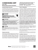
Indoor
Coil
Accumulator
Outdoor
Coil
Reversing Valve
(Energized)
Indoor
Coil
Accumulator
Outdoor
Coil
Reversing Valve
(De-Energized)
Typical Heat Pump System in Heating
Typical Heat Pump System in Cooling

20
SCHEDULED MAINTENANCE
Package heat pumps require regularly scheduled mainte-
nance to preserve high performance standards, prolong the
service life of the equipment, and lessen the chances of costly
failure.
In many instances the owner may be able to perform some
of the maintenance; however, the advantage of a service con-
tract, which places all maintenance in the hands of a trained
serviceman, should be pointed out to the owner.
WARNING
ONCE A MONTH
1. Inspect the return filters of the evaporator unit and clean
or change if necessary. NOTE: Depending on operation
conditions, it may be necessary to clean or replace the
filters more often. If permanent type filters are used, they
should be washed with warm water and dried.
2. When operating on the cooling cycle, inspect the con-
densate line piping from the evaporator coil. Make sure
the piping is clear for proper condensate flow.
ONCE A YEAR
Qualified Service Personnel Only
1. Clean the indoor and outdoor coils.
2. Clean the cabinet inside and out .
3. Motors are permanently lubricated and do not require oil-
ing. TO AVOID PREMATURE MOTOR FAILURE, DO NOT
OIL.
4. Manually rotate the outdoor fan and indoor blower to be
sure they run freely.
5. Inspect the control panel wiring, compressor connections,
and all other component wiring to be sure all connec-
tions are tight. Inspect wire insulation to be certain that
it is good.
6. Check the contacts of the compressor contactor. If
they are burned or pitted, replace the contactor.
7. Using a halide or electronic leak detector, check all
piping and etc. for refrigerant leaks.
TEST EQUIPMENT
Proper test equipment for accurate diagnosis is as essen-
tial as regular hand tools.
The following is a must for every service technician and
service shop:
1. Thermocouple type temperature meter - measure dry
bulb temperature.
2. Sling psychrometer- measure relative humidity and wet
bulb temperature.
3. Amprobe - measure current.
4. Volt-Ohm Meter - testing continuity, capacitors, motor
windings and voltage.
5. Accurate Leak Detector - testing for refrigerant leaks.
6. High Vacuum Pump - evacuation.
7. Electric Vacuum Gauge, Manifold Gauges and high
vacuum hoses - to measure and obtain proper vacuum.
8. Accurate Charging Cylinder or Electronic Scale - mea-
sure proper refrigerant charge.
9. Inclined Manometer - measure static pressure and pres-
sure drop across coils.
Other recording type instruments can be essential in solv-
ing abnormal problems, however, in many instances they
may be rented from local sources.
Proper equipment promotes faster, more efficient service,
and accurate repairs with less call backs.
/