Amana CHPF User manual

Type
User manual

Amana CHPF is a horizontal two-way coil designed for use with furnaces. It features a compact design for easy installation, a secondary condensate drain connection, and is suitable for both residential and commercial applications. The coil also includes a check style flowrator for refrigerant management and can be used with a variety of refrigerants.

Amana CHPF is a horizontal two-way coil designed for use with furnaces. It features a compact design for easy installation, a secondary condensate drain connection, and is suitable for both residential and commercial applications. The coil also includes a check style flowrator for refrigerant management and can be used with a variety of refrigerants.

Important Safety Instructions
The following symbols and labels are used throughout this
manual to indicate immediate or potential safety hazards. It is
the owner’s and installer’s responsibility to read and comply
with all safety information and instructions accompanying these
symbols. Failure to heed safety information increases the risk
of personal injury, property damage, and/or product damage.
WARNING
CAUTION
Hazards or unsafe practices could result in property
damage, product damage, severe personal injury or
death.
Hazards or unsafe practices which may result in property
damage, product damage, personal injury or death.
HIGH VOLTAGE!
Disconnect ALL power before servicing.
Multiple power sources may be present.
Failure to do so may cause property damage,
personal injury or death.
WARNING
ONLY individuals meeting the requirements of an
“Entry Level Technician” as specified by the Air
Conditioning and Refrigeration Institute (ARI) may use
this information. Attempting to install or repair this
unit without such background may result in product
damage, personal injury, or death.
WARNING
Shipping Inspection
Upon receiving the product, inspect it for damage from ship-
ment. Shipping damage, and subsequent investigation is the
responsibility of the carrier. Verify the model number, specifi-
cations, electrical characteristics, and accessories are cor-
rect prior to installation. The distributor or manufacturer will not
accept claims from dealers for transportation damage or in-
stallation of incorrectly shipped units.
Codes & Regulations
This product is designed and manufactured to comply with
national codes. Installation in accordance with such codes and/
or prevailing local codes/regulations is the responsibility of the
installer. The manufacturer assumes no responsibility for equip-
ment installed in violation of any codes or regulations.
HORIZONTAL TWO-WAY COIL
INSTALLATION INSTRUCTIONS
Goodman Manufacturing Company, L.P. © 2005-2006
2550 North Loop West, Suite 400, Houston, TX 77092
www.goodmanmfg.com -or- www.amana-hac.com
P/N: IO-285B Date: June 2006
The United States Environmental Protection Agency (EPA)
has issued various regulations regarding the introduc-
tion and disposal of refrigerants. Failure to follow these
regulations may harm the environment and can lead to
the imposition of substantial fines. Should you have any
questions please contact the local office of the EPA.
Replacement Parts
When reporting shortages or damages, or ordering repair parts,
give the complete product model and serial numbers as stamped
on the product. Replacement parts for this product are avail-
able through your contractor or local distributor. For the loca-
tion of your nearest distributor consult the white business
pages, the yellow page section of the local telephone book or
contact: SERVICE PARTS DEPARTMENT
GOODMAN MANUFACTURING COMPANY, L.P.
2550 NORTH LOOP WEST, SUITE 400
HOUSTON, TEXAS 77092
(713) 861 – 2500
Pre-Installation Instructions
Carefully read all instructions for the installation prior to install-
ing product. Make sure each step or procedure is understood
and any special considerations are taken into account before
starting installation. Assemble all tools, hardware and sup-
plies needed to complete the installation. Some items may
need to be purchased locally. Make sure everything needed to
install the product is on hand before starting.
Application Information
Install this coil upstream (discharge air) of the furnace. This
coil is bi-directional coil and can be installed in either the left or
right direction. The coil is factory shipped for right side applica-
tion. Determine the coil direction by the side that allows the
best access.
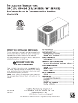
RIGHT APPLICATION LEFT APPLICATION
Figure 1
Front View (for Right & Left Hand Application)
To reverse from right to left application, relocate the front rail to
the back, and the back rail to the front. Then attach flanges to
the discharge side of the unit.
If the coil and furnace combination are not similar in depth and
width, use a field-supplied transition to center the furnace and
coil openings. The supplied Z-bracket attachment should be
used to attach the coil to a narrower Goodman or Amana®
2
furnace when the furnace is one size smaller than the coil (i.e.
coil height = 17.5-inches and furnace width = 14-inches) (See
figure 3).
Duct Flange Attachment
1. Remove the shipping bracket spanning the A-Coil apex
to the rear of the wrapper on all models prior to installation.
2. The bottom duct flange for the supply plenum side is
shipped unattached. Carefully insert the flange into bottom rail
and use a 5/16" screw to attach at the middle of the flange.
BACK RAIL
FRONT RAIL
DUCT FLANGE
SHIPPING BRACKET
TO BE REMOVED PRIOR
TO INSTALLATION
DUCT FLANGES ARE IN THE
ACCESSORY KIT INCLUDED
WITH THIS UNIT. REMOVE THE
DUCT FLANGES FROM KIT
PACKAGING AND INSTALL AS
INSTRUCTED IN STEP 3.
Figure 2
Horizontal Right Application
3. Using the hardware and brackets provided, attach the coil
to the furnace then attach the plenum to the coil (Figure 3).
COIL
PLENUM
FRONT BRACKET
ACCESSORY
FURNACE
TOP & BACK
BRACKET
ACCESSORY
ACCESSORY
TOP & BACK
ACCESSORY
FRONT BRACKET
COIL
FURNACE
BRACKET
PLENUM
(Z-BRACKET WITH NARROW FURNACE)
Figure 3
Installation of Furnace, Coil and Plenum
Using tape or mastic seal between the coil and furnace and
the coil and plenum.
Condensate Drain Piping
When coils are installed above ceilings, or in other locations
where damage from condensate overflow may occur, it is MAN-
DATORY to install a field fabricated auxiliary drain pan under
the coil cabinet enclosure. Drain lines from the auxiliary pan
must be installed and terminated so that the homeowner can
see water discharges.
Primary condensate drain connections are located in the drain
pan at the bottom of the coil/enclosure assembly. Use the
female (3/4 fpt) threaded fitting that protrudes outside of the
enclosure for external connections.
1. Ensure drain pan hole is NOT obstructed.
2. To prevent potential sweating and dripping on finished
space, it may be necessary to insulate the condensate
drain line located inside the building. Use Armaflex® or
similar material.
A Secondary Condensate Drain Connection, now called for by
many building codes, has been provided. Pitch the drain line
1/4" per foot to provide free drainage. Install a condensate trap
to ensure proper drainage.
If secondary drain is not installed, the secondary access
must be plugged.
CAUTION
Do not use this coil on OIL furnaces or any application
where the temperature of the drain pan may exceed
300ºF. A field fabricated metal drain pan should be used
for these type of applications. Failure to follow this
warning may result in property damage and/or personal
injury.
WARNING
Cased Coil
3" MIN.
POSITIVE LIQUID SEAL
REQUIRED AT TRAP
Drain
Connection
2" MIN.
Figure 4
Refrigerant Lines
A quenching cloth is strongly recommended to
prevent scorching or marring of the equipment
finish when welding close to the painted surfaces.
Use brazing alloy of 5% minimum silver content.
WARNING
All cut ends are to be round, burr free, and cleaned. Any other
condition increases the chance of a refrigerant leak. Use a
pipe cutter to remove the closed end of the spun closed suc-
tion line.
To avoid overheating after brazing, quench all welded joints
with water or a wet rag.
3
For the correct tubing size, follow the specification for the con-
denser/heat pump
The coil is shipped under pressure. Follow these
instructions to prevent injury.
WARNING
Special Instructions
This coil comes equipped with a check style flowrator for refrig-
erant management. For most installations with matching ap-
plications, no change to the flowrator orifice is required. How-
ever, in mix-matched applications, a flowrator change may be
required. See the Goodman piston kit chart or consult your
local distributor for details regarding mix-matched orifice siz-
ing. If the mix-match application requires a different piston size,
change the piston in the distributor on the indoor coil before
installing the coil and follow the procedure shown below.
1. Loosen the 13/16 nut 1 TURN ONLY to allow high pres-
sure tracer gas to escape. No gas indicates a possible
leak.
2. After the gas has escaped, remove the nut and discard
the black or brass cap.
3. Remove the check piston to verify it is correct and then
replace the piston. See piston kit chart in instructions.
4. Use a tube cutter to remove the spin closure on the suc-
tion line.
5. Remove the tailpiece clamped to the exterior and slide
the 13/16 nut into place.
6. Braze tailpiece to the line set liquid tube.
TAILPIECE
13/16" NUT
PLASTIC or BRASS CAP
WHITE
TEFLON SEAL
PISTON
Figure 1
7. Insert the suction line into the connection, slide the insu-
lation and the rubber grommet at least 18" away from the
braze joint. Braze suction line.
8. AFTER THE TAILPIECE HAS COOLED, confirm posi-
tion of the white Teflon® seal and hand tighten the 13/16
nut.
9. Torque the 13/16 nut to 10-30 ft-lbs. or tighten 1/6 turn.
Excessive torque can cause orifices to stick. Use the proper
torque settings when tightening orifices.
CAUTION
10. Replace suction line grommet and insulation.
RUBBER
GROMMET
SUCTION LINE
WITH SPIN CLOSURE
Figure 2
11. Check fittings for leaks after complete installation. Evacu-
ate and charge on the low side.
NOTE: With the piston in the distributor, the seal end should
point inside the distributor body and should not be seen when
looking into the end of distributor. Make sure the piston is free
to rotate, and move up and down in the distributor body.
IMPORTANT: Note 2 in the Goodman piston chart does not
apply to CH coils.
4
NOTE: SPECIFICATIONS AND PERFORMANCE DATA LISTED
HEREIN ARE SUBJECT TO CHANGE WITHOUT NOTICE
Quality Makes the Difference!
All of our systems are designed and manufactured with the same high quality standards regard-
less of size or efficiency. We have designed these units to significantly reduce the most frequent
causes of product failure. They are simple to service and forgiving to operate. We use quality
materials and components. Finally, every unit is run tested before it leaves the factory. That’s
why we know. . .There’s No Better Quality.
Visit our websites at www.goodmanmfg.com or amana-hac.com for information on:
• Products
• Warranties
• Customer Services
• Parts
• Contractor Programs and Training
• Financing Options
© 2005-2006 Goodman Manufacturing Company, L.P.
  • Page 1 1
  • Page 2 2
  • Page 3 3
  • Page 4 4

Amana CHPF User manual

Type
User manual

Amana CHPF is a horizontal two-way coil designed for use with furnaces. It features a compact design for easy installation, a secondary condensate drain connection, and is suitable for both residential and commercial applications. The coil also includes a check style flowrator for refrigerant management and can be used with a variety of refrigerants.

Ask a question and I''ll find the answer in the document

Finding information in a document is now easier with AI