Page is loading ...

Galaxy 4000
40 – 75KVA
Uninterruptible Power Systems
Installation and User Manual
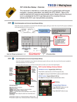
Standard Features
◗ Emergency Power Off
button with safety cover.
◗ Interactive Display Panel.
www.mgeups.com


Installation and User Manual
i
Galaxy 4000
40 – 75KVA
Uninterruptible Power Systems
Installation and User Manual
Revision History
Galaxy 4000 Installation and User Manual 86-173010-00
Revision: A00 ECN#: 004540 12/2005
Copyright © 2005 MGE UPS SYSTEMS, INC.
All rights reserved. Printed in U.S.A.
MGE UPS SYSTEMS, INC.
1660 Scenic Avenue
Costa Mesa, CA 92626
(714) 557-1636
Customer Care Center:
1-800-438-7373
(Hours: 24/7)
i86-173010-00 A00

Galaxy 4000
Important Safety Instructionsii 86-173010-00 A00
IMPORTANT SAFETY INSTRUCTIONS
SAVE THESE INSTRUCTIONS – This manual contains important instructions for Galaxy
4000 that must be followed during operation and maintenance of the equipment.
WARNING
Opening enclosures expose hazardous voltages. Always refer service to qualified
personnel only.
ATTENTION
L'ouverture des cabinets expose des tensions dangereuses. Assurez-vous
toujours que le service ne soit fait que par des personnes qualifiees.
WARNUNG!
Das öffnen der Gehäuse legen gefährliche Spannungen bloss. Service sollte
immer nur von qualifizierten Personal durchgeführt werden.
WARNING
As standards, specifications, and designs are subject to change, please ask for
confirmation of the information given in this publication.
ATTENTION
Comme les normes, spécifications et produits peuvent changer, veuillez
demander confirmation des informations contenues dans cette publication.
WARNUNG!
Normen, Spezifizierungen und Pläne unterliegen Anderungen. Bitte verlangen Sie
eine Bestätigung über alle Informationen, die in dieser Ausgabe gemacht wurden.
NOTE
This equipment has been tested and found to comply with the limits for a Class
A digital device, pursuant to part 15 of the FCC rules. These limits are designed
to provide reasonable protection against harmful interference when the
equipment is operated in a commercial environment.
This equipment generates, uses, and can radiate radio frequency energy and, if
not installed and used in accordance with the instruction manual, may cause
harmful interference to radio communications. Operation of this equipment in a
residential area is likely to cause harmful interference in which case the user will
be required to correct the interference at user's own expense.
WARNING
To reduce the risk of fire or electric shock, install in a controlled indoor environ-
ment free of conductive contaminants.
This equipment is intended only for installations in a RESTRICTED ACCESS
LOCATION.
ATTENTION
Pour réduire le riske d'inccendie ou d'électrocution, installer dans une enciente
intérieure contrôlée en température et humidité et sans contaminants conducteurs.
Ce matériel est destiné seulement pour des installations dans un EMPLACEMENT
RESTREINT D'ACCES.
WARNUNG!
Um die Gefahr von Feuer und elektrischem Schock zu reduzieren, muss das
Gerät in einem temperatur – und feuchtigkeitskontrollierten Raum, frei von
leitungsfähigen Verunreinigungen, installiert werden. Dieses Gerät ist nur für die
Installation an einem Ort mit qeingeschränkter Zugangserlaubnis vorgesehen.
Diese Ausrüstung ist nur für Anlagen in einem EINGESCHRäNKTEN ZUGRIFF
STANDORT bestimmti.

Installation and User Manual
iii86-173010-00 A00
WARNING HIGH LEAKAGE CURRENT. Earth connection essential before connecting
supply.
ATTENTION COURANT DE FUITE ELEVE. Raccordement a la terre indispensable
avant le raccordement au reseau.
WARNUNG! Hoher Ableitstrom Vor Inbetriebnahme Schutzleiterverbindung herstellen.
Certification Standards – Three Phase UPS
◗ IEC1004/ANSI C62.41 Standards for Surge Withstand Ability.
◗ FCC Part 15, Subpart J, Class A.
◗ UL/CUL 1778, Standards for Uninterruptible Power Supply Equipment.
◗ NEMA PE 1 - Uninterruptible Power Systems.
◗ NFPA 70 – National Electrical Code.
◗ ISO 9001.
Safety of Persons
◗ The UPS has its own internal power source (the battery). Consequently, the power terminals may be energized
even if the UPS is disconnected from the AC power source.
◗ The UPS must be properly grounded.
◗ The battery supplied with the UPS contains small amounts of toxic materials. To avoid accidents, the directives
listed below must be observed:
- Never burn the battery (risk of explosion).
- Do not attempt to open the battery (the electrolyte is dangerous for the eyes and skin).
- Comply with all applicable regulations for the disposal of the battery.
- Batteries constitute a danger (electrical shock, burns). The short-circuit current may be very high.
- Precautions must be taken for all handling: remove watches, rings, bracelets and any other metal objects,
use tools with insulated handles.
- Do not lay tools or metal parts on top of batteries.
Product Safety
◗ Upstream protection must be installed and be easily accessible.
◗ The UPS can be disconnected from the AC power source by opening the input protective devices.
◗ UPS must be connected to a nearby power source that is easily accessible.
◗ Never block the ventilation openings of the UPS.
◗ The UPS must be installed in a controlled environment.
Special Precautions
◗ The UPS connection instructions and operation described in the manual must be followed in the indicated order.
◗ Check that the indications on the rating nameplate correspond to your AC powered system and to the actual
electrical consumption of all the equipment to be connected to the UPS.
◗ Before and after the installation, if the UPS remains de-energized for a long period, the UPS must be energized
for a period of 24 hours, at least once every 3 months (for a normal storage temperature less than 25°C). This
charges the battery, thus avoiding possible irreversible damage.
Environment
This product has been designed to respect the environment; It does not contain any Chlorofluorocarbon (CFC) or
Hydrochlorofluorocarbon (HCFC).
UPS recycling at the end of service life; MGE UPS SYSTEMS, INC. undertakes to recycle, by certified companies
and in compliance with all applicable regulations, all UPS products recovered at the end of their service life (contact
your MGE UPS SYSTEMS, INC. branch office).
Packing; UPS packing materials must be recycled in compliance with all applicable regulations.
WARNING: This product contains lead-acid batteries. Lead is a dangerous substance for the environment if it is not
properly recycled by specialized companies.
Certification Standards, Safety of Persons

Galaxy 4000
iv 86-173010-00 A00

Contents
Contents
I86-173010-00 A00
section description . . . . . . . . . . . . . . . . . . . . . . . . . . . . . . . . . . . . . . . . . . .page
Revision History . . . . . . . . . . . . . . . . . . . . . . . . . . . . . . . . . . . . . . . . . . .i
IMPORTANT SAFETY INSTRUCTIONS . . . . . . . . . . . . . . . . . . . . . . . ii
Certification Standards - Three Phase UPS . . . . . . . . . . . . . . . . . . . . iii
Safety of Persons . . . . . . . . . . . . . . . . . . . . . . . . . . . . . . . . . . . . . . . . iii
Product Safety . . . . . . . . . . . . . . . . . . . . . . . . . . . . . . . . . . . . . . . . . . iii
Special Precautions . . . . . . . . . . . . . . . . . . . . . . . . . . . . . . . . . . . . . . iii
Environment . . . . . . . . . . . . . . . . . . . . . . . . . . . . . . . . . . . . . . . . . . . . .iii
Symbol Usage . . . . . . . . . . . . . . . . . . . . . . . . . . . . . . . . . . . . . . . . . . . V
Section Descriptions . . . . . . . . . . . . . . . . . . . . . . . . . . . . . . . . . . . . . .V
Section 1 Introduction
1.0 Scope . . . . . . . . . . . . . . . . . . . . . . . . . . . . . . . . . . . . . . . . . . . . . .1 — 1
1.1 General Description . . . . . . . . . . . . . . . . . . . . . . . . . . . . . . . . . . .1 — 1
1.2 Major Components . . . . . . . . . . . . . . . . . . . . . . . . . . . . . . . . . . . .1 — 2
1.3 Single Line Diagram . . . . . . . . . . . . . . . . . . . . . . . . . . . . . . . . . . .1 — 2
1.4 Galaxy 4000 Standard Cabinets . . . . . . . . . . . . . . . . . . . . . . . . .1 — 3
1.5 Preparation for Operation . . . . . . . . . . . . . . . . . . . . . . . . . . . . . . .1 — 3
1.6 Cabinet Placement . . . . . . . . . . . . . . . . . . . . . . . . . . . . . . . . . . . .1 — 3
1.7 Heat Rejection and Air Flow . . . . . . . . . . . . . . . . . . . . . . . . . . . . .1 — 3
1.8 Cabinet Clearances . . . . . . . . . . . . . . . . . . . . . . . . . . . . . . . . . . .1 — 4
1.9 Conduit Plate Locations for Bottom Entry . . . . . . . . . . . . . . . . . .1 — 4
1.10 Conduit Plate Locations for Top Entry . . . . . . . . . . . . . . . . . . . . .1 — 5
1.11 Preparation for Storage . . . . . . . . . . . . . . . . . . . . . . . . . . . . . . . .1 — 6
Section 2 Setup and Installation
2.0 Scope . . . . . . . . . . . . . . . . . . . . . . . . . . . . . . . . . . . . . . . . . . . . . .2 — 1
2.1 Installation Steps . . . . . . . . . . . . . . . . . . . . . . . . . . . . . . . . . . . . .2 — 1
2.2 Environmental and Electrical Specifications . . . . . . . . . . . . . . . . .2 — 1
2.2.1 Environmental Recommendations . . . . . . . . . . . . . . . . . . . . . . . .2 — 1
2.2.2 Electrical Specifications . . . . . . . . . . . . . . . . . . . . . . . . . . . . . . . .2 — 2
2.3 Electrical Connections . . . . . . . . . . . . . . . . . . . . . . . . . . . . . . . . .2 — 2
2.3.1 UPS Connections . . . . . . . . . . . . . . . . . . . . . . . . . . . . . . . . . . . . .2 — 3
2.3.2 Main AC Input Connections . . . . . . . . . . . . . . . . . . . . . . . . . . . . .2 — 3
2.2.3 Bypass AC Input Connections (optional) . . . . . . . . . . . . . . . . . . .2 — 3
2.3.4 AC Output Connections . . . . . . . . . . . . . . . . . . . . . . . . . . . . . . . .2 — 3
2.3.5 Battery Connections . . . . . . . . . . . . . . . . . . . . . . . . . . . . . . . . . . .2 — 4
2.3.6 Remote Emergency Power Off Connections . . . . . . . . . . . . . . . .2 — 4
2.3.7 Battery Control Connections . . . . . . . . . . . . . . . . . . . . . . . . . . . .2 — 4
2.3.8 External Maintenance Bypass Control Connections (optional) . .2 — 5
2.3.9 Accessories Outlets . . . . . . . . . . . . . . . . . . . . . . . . . . . . . . . . . . .2 — 5

Galaxy 4000
ContentsII 86-173010-00 A00
Section 2 Setup and Installation (continued)
section description page
2.4 Relay Communication Card Contacts . . . . . . . . . . . . . . . . . . . . .2 — 5
2.4.1 Relay Communication Card Connections . . . . . . . . . . . . . . . . . .2 — 6
2.4.2 Characteristics of the Output Contacts . . . . . . . . . . . . . . . . . . . .2 — 7
2.4.3 Characteristics of the Input Contacts . . . . . . . . . . . . . . . . . . . . . .2 — 7
Section 3 Display Panel
3.0 Scope . . . . . . . . . . . . . . . . . . . . . . . . . . . . . . . . . . . . . . . . . . . . . .3 — 1
3.1 Operator Interface Keys and Indicators . . . . . . . . . . . . . . . . . . . .3 — 1
3.1.1 LED Indicator Functions . . . . . . . . . . . . . . . . . . . . . . . . . . . . . . . .3 — 2
3.1.2 Screen Saver . . . . . . . . . . . . . . . . . . . . . . . . . . . . . . . . . . . . . . . .3 — 2
3.1.3 Operational Summary Screen . . . . . . . . . . . . . . . . . . . . . . . . . . .3 — 2
3.2 Display Menu Structure . . . . . . . . . . . . . . . . . . . . . . . . . . . . . . . .3 — 3
3.3 Main Menu Screen . . . . . . . . . . . . . . . . . . . . . . . . . . . . . . . . . . . .3 — 4
3.4 Measurements . . . . . . . . . . . . . . . . . . . . . . . . . . . . . . . . . . . . . . .3 — 4
3.4.1 Battery Measurements Screen . . . . . . . . . . . . . . . . . . . . . . . . . . .3 — 4
3.4.2 Power Measurements Screen . . . . . . . . . . . . . . . . . . . . . . . . . . .3 — 5
3.4.3 Current Measurements Screen . . . . . . . . . . . . . . . . . . . . . . . . . .3 — 5
3.4.4 Voltage Measurements Screen . . . . . . . . . . . . . . . . . . . . . . . . . .3 — 6
3.4.5 Frequency Measurements Screen . . . . . . . . . . . . . . . . . . . . . . . .3 — 6
3.4.6 Ratios Screen . . . . . . . . . . . . . . . . . . . . . . . . . . . . . . . . . . . . . . . .3 — 6
3.5 Mimic Diagrams . . . . . . . . . . . . . . . . . . . . . . . . . . . . . . . . . . . . . .3 — 7
3.6 Status Screen . . . . . . . . . . . . . . . . . . . . . . . . . . . . . . . . . . . . . . . .3 — 7
3.7 Settings Screen . . . . . . . . . . . . . . . . . . . . . . . . . . . . . . . . . . . . . .3 — 8
3.8 Commands Screen . . . . . . . . . . . . . . . . . . . . . . . . . . . . . . . . . . . .3 — 9
3.9 Startup Procedure Screen . . . . . . . . . . . . . . . . . . . . . . . . . . . . . .3 — 9
Section 4 Operation
4.0 Scope . . . . . . . . . . . . . . . . . . . . . . . . . . . . . . . . . . . . . . . . . . . . . .4 — 1
4.1 Preparing for Startup . . . . . . . . . . . . . . . . . . . . . . . . . . . . . . . . . .4 — 1
4.1.1 Pre-Startup Safety Check List . . . . . . . . . . . . . . . . . . . . . . . . . . .4 — 1
4.2 Normal Startup Procedure . . . . . . . . . . . . . . . . . . . . . . . . . . . . . .4 — 3
4.3 Post Startup Safety Check List . . . . . . . . . . . . . . . . . . . . . . . . . .4 — 4
4.4 Shutdown Procedure . . . . . . . . . . . . . . . . . . . . . . . . . . . . . . . . . .4 — 4
4.5 Shutdown Using EPO . . . . . . . . . . . . . . . . . . . . . . . . . . . . . . . . . .4 — 4
4.6 Recovery from EPO . . . . . . . . . . . . . . . . . . . . . . . . . . . . . . . . . . .4 — 4
Section 5 Maintenance
5.0 Scope . . . . . . . . . . . . . . . . . . . . . . . . . . . . . . . . . . . . . . . . . . . . . .5 — 1
5.1 Servicing Batteries . . . . . . . . . . . . . . . . . . . . . . . . . . . . . . . . . . . .5 — 1

Installation and User Manual
III86-173010-00 A00
Section 6 Warranty, Registration & Customer Support
description page
MGE Warranty & Proprietary Rights for Three Phase Products . . . . . . . . . . . . . .6 – 1
MGE Standard Three Phase Warranty
Proprietary Rights Statement
Warranty and Product Registration . . . . . . . . . . . . . . . . . . . . . . . . . . . . . . . . . . . .6 – 2
User Information
Product information
Warranty Extension (Warranty+)
MGE Customer Care Center . . . . . . . . . . . . . . . . . . . . . . . . . . . . . . . . . . . . . . . .6 – 3
Technical Support and Product Services
Who To Contact
Scheduling Field Service Engineer Support
Return Policy for Repair of Three Phase Products (RGA)
Caution: Record All Serial Numbers! . . . . . . . . . . . . . . . . . . . . . . . . . . . . . . . . . .6 – 4
Glossary
Reorder Form
Contents

Galaxy 4000
IV 86-173010-00 A00
Figures
figure description page
1-1 Galaxy 4000 UPS System . . . . . . . . . . . . . . . . . . . . . . . . . . . . . . . . . . . .1 — 1
1-2 Galaxy 4000 UPS System - Single Line Diagram . . . . . . . . . . . . . . . . . .1 — 2
1-3 Cabinet Placement, Airflow and Recommended Clearances . . . . . . . . .1 — 4
1-4 Configuration for Bottom Entry . . . . . . . . . . . . . . . . . . . . . . . . . . . . . . . . .1 — 5
1-5 Configuration for Top Entry . . . . . . . . . . . . . . . . . . . . . . . . . . . . . . . . . . . .1 — 5
2-1 Typical Power Connections . . . . . . . . . . . . . . . . . . . . . . . . . . . . . . . . . . .2 — 4
2-3 Relay Communication Card . . . . . . . . . . . . . . . . . . . . . . . . . . . . . . . . . . .2 — 6
3-1 Display Panel Keys and Indicators . . . . . . . . . . . . . . . . . . . . . . . . . . . . . .3 — 1
3-2 Screen Saver . . . . . . . . . . . . . . . . . . . . . . . . . . . . . . . . . . . . . . . . . . . . . .3 — 2
3-3 Operational Summary screen . . . . . . . . . . . . . . . . . . . . . . . . . . . . . . . . . .3 — 2
3-4 UPS Display Menu Structure . . . . . . . . . . . . . . . . . . . . . . . . . . . . . . . . . .3 — 3
3-5 Main Menu screen . . . . . . . . . . . . . . . . . . . . . . . . . . . . . . . . . . . . . . . . . .3 — 4
3-6 Battery Measurements screen . . . . . . . . . . . . . . . . . . . . . . . . . . . . . . . . .3 — 4
3-7 Power Measurements screen . . . . . . . . . . . . . . . . . . . . . . . . . . . . . . . . . .3 — 5
3-8 Current Measurements screen . . . . . . . . . . . . . . . . . . . . . . . . . . . . . . . . .3 — 5
3-9 Voltage Measurements screen . . . . . . . . . . . . . . . . . . . . . . . . . . . . . . . . .3 — 6
3-10 Frequency Measurements screen . . . . . . . . . . . . . . . . . . . . . . . . . . . . . .3 — 6
3-11 Ratios screen . . . . . . . . . . . . . . . . . . . . . . . . . . . . . . . . . . . . . . . . . . . . . .3 — 6
3-12 Mimic Diagrams screen . . . . . . . . . . . . . . . . . . . . . . . . . . . . . . . . . . . . . .3 — 7
3-13 Status screen . . . . . . . . . . . . . . . . . . . . . . . . . . . . . . . . . . . . . . . . . . . . . .3 — 7
3-14 Settings screens . . . . . . . . . . . . . . . . . . . . . . . . . . . . . . . . . . . . . . . . . . . .3 — 8
3-15 Commands screens . . . . . . . . . . . . . . . . . . . . . . . . . . . . . . . . . . . . . . . . .3 — 9
4-1 Galaxy 4000 Device Locations . . . . . . . . . . . . . . . . . . . . . . . . . . . . . . . . .4 — 2
Tables
table description page
1-1 Heat Rejection Data . . . . . . . . . . . . . . . . . . . . . . . . . . . . . . . . . . . . . . . . .1 — 4
2-1 Electrical Specifications for the Galaxy 4000 . . . . . . . . . . . . . . . . . . . . . .2 — 2
2-2 Relay Contacts (communication card) . . . . . . . . . . . . . . . . . . . . . . . . . . .2 — 5
3-1 Three LED Indicators . . . . . . . . . . . . . . . . . . . . . . . . . . . . . . . . . . . . . . . .3 — 2
Contents

Installation and User Manual
V86-173010-00 A00
Symbol Usage
This manual uses five icon symbols with text to convey important information and tips.
WARNING Indicates information provided to protect the user and service personnel against
safety hazards and/or possible equipment damage.
CAUTION Indicates information provided to protect the user and service personnel against
possible equipment damage.
ELECTRICAL Indicates information provided to protect the user and service personnel against
possible electrical hazard and equipment damage.
IMPORTANT Indicates information provided as an operating instruction, or as an operating tip.
NOTE Indicates information provided as an operating tip or an equipment feature.
Section Descriptions
1 Introduction
Provides a general description of the Galaxy 4000 systems intended use, major components, mechanical and
environmental specifications.
2 Setup and Installation
Guides the user through tools and equipment required for unpacking and performing connections required for initial
installation. Included are the electrical specifications, environmental recommendations and connection details.
3 Display Panel
Describes the operator interface screens, keys, and mimic diagram.
4 Operation
Provides startup, shutdown, and normal operation of the Galaxy 4000 UPS. Included are pre and post startup safety
checklists.
5 Maintenance
Describes maintenance and safety information on servicing batteries for the Galaxy 4000.
A Glossary provides definitions of abbreviations and terms used in this manual.
Symbol Usage and Section Descriptions

Galaxy 4000
VI 86-173010-00 A00

Introduction
1.0 Scope
Provides a general description of the Galaxy 4000 systems intended use, major components, mechanical and
environmental specifications.
1.1 General Description
The Galaxy 4000 is the world’s first data center grade Uninterruptible Power Supply system designed specifically
for mid-range enterprise level applications. The Galaxy 4000 family consists of units available in power ratings from
40 - 75KVA, and are optimized for compatibility with nonlinear computer-type loads.
By incorporating the Ultra High Availability Topology (UHAT), the Galaxy 4000 family of UPS systems are designed
to provide the optimal level of reliability and to react to any power disturbance in an inherently safe way to protect
the critical load. The Galaxy 4000 all-in-one design incorporates every feature into one compact cabinet, including
a graphical user interface, power factor corrected input, and communication cards that support network based
power management.
The Galaxy 4000 UPS and its auxiliary equipment are designed for installation in a room where humidity and
temperature can be controlled.
The Galaxy 4000 UPS and auxiliary equipment is listed for safety by Underwriters Laboratories, Inc. (UL) under UL
Standard 1778 – Uninterruptible Power Systems; and also listed by Underwriters Laboratories (CUL) under Canadian
Standards Association (CSA) standard C22.107.
Figure 1-1: Galaxy 4000 UPS System.
1 — 186-173010-00 A00 Introduction

Galaxy 4000
1 — 2 86-173010-00 A00
1.2 Major Components
Rectifier Converts AC input voltage to DC voltage. The rectifier uses IGBT (Insulated G a t e
Bipolar Transistor) power transistors and a Pulse Width Modulated (PWM)
technique to provide input power factor correction and to minimize any harmonic
reflected onto the input power lines.
Inverter Converts DC voltage from the rectifier or from the batteries into AC output voltage
to maintain the attached load. This module uses the IGBT technology to provide
digital power quality.
Static Switch Automatically supplies the attached load from the bypass source when the inverter
is off.
Battery System Stores energy for utilization by the inverter and attached load in the event that utility
AC power is lost or is of unacceptable quality.
1.3 Single Line Diagram
During normal operation, the utility power (Main input) is supplied to the UPS rectifier. The rectifier converts the AC
power to DC that is supplied to the inverter. The inverter converts the DC voltage to three-phase regulated AC
voltage, which is supplied to the attached load.
During power failure conditions, the inverter is supplied by the stored energy in the battery system, and the load is
powered continuously with no interruption.
The Galaxy 4000 UPS is designed for internal operation of 208VAC input and output. External batteries, and an
output distribution panel may be contained in auxiliary cabinets similar in design to the Galaxy 4000 cabinet.
Batteries or external maintenance bypass circuit breakers may also be contained in third party cabinets or wall
mounted units.
Figure 1-2: Galaxy 4000 UPS System – Single Line Diagram.
Introduction
BYPASS
INPUT
TB3
A
B
C
A
B
C
N
G
INPUT
STATIC
SWITCH
INPUT
FUSES
Q1
Q4S
BATTERY
STATIC SWITCH
BATTERY
CHARGER
KB (OPTIONAL)
CONTROL CONNECTIONS
(SEE UPS INSTALLATION DWG)
TB4
REPO ON MBS
SUPPLIED BY MGE &
CON NECTED BY CUSTOMER
(ADJACENT VERSION)
SUPPLIED & CONNECTED
BY CUSTOMER
(STAND ALONE VERSION)
TO
CRITICAL
LOAD
OUTPUT
TB2
Q3BP (OPTIONAL)
78910
A
B
C
N
G
Q5N
PFC
BOOST
RECTIFIER
INVERTER
OUTPUT
STATIC
SWITCH
BYPASS
STATIC
SWITCH
UPS
MAIN
INPUT
TB1
OPTIONAL
BYPASS
INPUT
208YVAC
MAIN
INPUT
208YVAC
KA
DISTRIBUTION
BATTERY
42 POLE
PANELBOARD
OUTPUT
CB
(OPTIONAL)
SUPPLIED BY MGE &
CONNECTED BY CUSTOMER
CB1 CB1
TB4
CB1 CB1

Installation and User Manual
1 — 386-173010-00 A00
1.4 Galaxy 4000 Standard Cabinets
The Galaxy 4000 individual cabinet dimensions are:
◗ UPS cabinet: 72.1in (1831mm) H x 33.5in (851mm) W x 35.6in (904mm) D.
◗ External battery cabinet: 72.1in (1831mm) H x 26.5in (673mm) W x 33.5in (851mm) D OR –
◗ External battery cabinet: 72.1in (1831mm) H x 33.5in (851mm) W x 33.5in (851mm) D.
◗ Distribution cabinet: 72.1in (1831mm) H x 19.5in (495mm) W x 33.5in (851mm) D.
The UPS cabinet is designed to provide for top and bottom entry of the utility power feed. An output voltage of
208VAC is standard with the Galaxy 4000 and does not require any additional cabinetry. The complete list of
additional cabinets that could be included with your Galaxy 4000 system are: external maintenance bypass wall
cabinet, external battery cabinet, and distribution cabinet.
The external battery cabinets are provided in two different cabinet sizes depending upon the battery type selected.
Up to four battery cabinets may be provided. The cabinets may be installed adjacent to the UPS or remotely and
are designed for top and bottom entry. The distribution cabinet provides a 42 pole panelboard, with an optional
submain circuit breaker. The cabinet is designed for top and bottom entry.
1.5 Preparation for Operation
Several items must be considered when preparing the Galaxy 4000 UPS system for operation.
First The UPS cabinet and its auxiliary cabinets must be arranged in the required configuration to insure that
the interconnection cables are located in the correct adjacent cabinets.
Second The cabinets must be in a location that provides for proper air flow and heat rejection.
Third The room in which the Galaxy 4000 UPS system is located must maintain environmental conditions within
recommended tolerances.
Forth All electrical connections must utilize the top or bottom conduit entries provided.
The following sections discuss these items in more detail.
1.6 Cabinet Placement
The complete UPS system may consist of one to three cabinets depending on the options selected. The UPS
cabinet allows system options to be selected based on the application. When facing the Galaxy 4000 UPS from the
front, the standard arrangement provides for any external batteries to be located on the right hand side, and the
distribution cabinet to be located on the left hand side of the UPS. Refer to Figure 1-3 for cabinet placement.
1.7 Heat Rejection and Air Flow
The Galaxy 4000 UPS cabinets generate heat and exhaust air through the top portion of its enclosures. Air intake
is through the bottom and front of the cabinet. All other cabinets are convection cooled. To assist you in planning for
your HVAC needs, heat rejection data is provided in Table 1-1. The cabinet airflow and recommended top clearance
are provided in Figure 1-3. The Galaxy 4000 is intended for use in an environment where control of temperature
and humidity is provided.
Introduction

Galaxy 4000
1 — 4 86-173010-00 A00
Figure 1-3: Cabinet Placement, Airflow and Recommended Clearances.
Table 1-1: Heat Rejection Data.
NOTE: To provide for adequate ventilation, a minimum of 36 inches clearance should
be maintained above the top of the Galaxy 4000 cabinet.
1.8 Cabinet Clearances
The Galaxy 4000 UPS cabinet top clearance of 36 inches for fan exhaust is recommended. Additionally, adequate
space must be included in the front and top of each cabinet (approx. 36 inches) to allow the doors/panels of the
cabinet to be opened for service and maintenance procedures.
For an installation where seismic requirements must be met, additional clearance at the side of the cabinet must be
included to accommodate the seismic anchors. Contact your local MGE Sales Representative to order. See Figure 1-4.
1.9 Conduit Plate Locations for Bottom Entry
Cable entry through the bottom is the standard preferred design for the Galaxy 4000 UPS cabinet. The bottom entry
conduit plate provides space for up to five (5) separate conduit entries. The plate is secured with screws which
should be retained for the conduit plate after the power connections are made. See Figure 1-4 for the location of
the bottom entry conduit plates.
Heat Rejection Data @ 208/208VAC
UPS cabinet 40KVA 50KVA 65KVA 75KVA
BTU/Hr 14,900 18,700 24,200 28,000
ALLOW 36" TOP CLEARANCE
FOR FAN EXHAUST AND SERVICE MAINTENANCE
AIR EXHAUST
DISPLAY PANEL
LEVELING
JACKS
CASTERS
UPS CABINET
Galaxy 4000
EXTERNAL BATTERY
CABINET
(Optional)
FRONT VIEW
?
!
!
234
1
(
(
DISTRIBUTION
CABINET
(Optional)
AIR INTAKE
Introduction

Installation and User Manual
1 — 586-173010-00 A00
Figure 1-4: Configuration for Bottom Entry.
1.10 Conduit Plate Locations for Top Entry
The UPS cabinet for the Galaxy 4000 is capable of accepting power input and output cables through a top entry.
The conduit plate on the top of the cabinet provides provisions for knockouts for conduit and is secured to the
cabinet with screws. See Figure 1-5.
Figure 1-5: Configuration for Top Entry.
26W BATTERY
(33W BATTERY)
DISTRIBUITION
UPS
(16) x 1.125 K.O.
(34) .857 K.O.
AIR EXHAUST
DO NOT BLOCK
16.5
16.7
8.9
33.5
18.8 32.0
76.5
(83.5)
25.0
(32.0)
9 x 20.5
CONDUIT
10 x 20.5
CONDUIT
AIR INTAKE
DO NOT BLOCK
SEISMIC BRACKET (optional)
(4 PLCS)
CABLE ENTRY PLATE
2.4
18.0
28.8
25.0
(32.0)
9.6
14.0
2.9
38.1
46.6
(53.6)
3.2
15.7
Introduction

1.11 Preparation for Storage
If the equipment is to be stored prior to installation, it should be stored in a cool, dry, well-ventilated location that is
protected against rain, splashing water, chemical agents, etc. The equipment should be covered with a tarpaulin or
plastic wrapper to protect it against dust, dirt, paint, or other foreign materials. See the section of this manual titled
"Environmental Recommendations" for recommended storage environmental conditions.
NOTE Batteries should be stored no longer than three (3) months at 25°C (77°F) or lower
prior to recharging. Exceeding the recommended ambient storage temperature
will reduce battery back-up time and may adversely affect battery life.
Galaxy 4000
Introduction1 — 6 86-173010-00 A00

Setup and Installation
2.0 Scope
Guides the user through tools and equipment required for unpacking and performing connections required for initial
installation. Included are the electrical specifications, environmental recommendations and connection details.
2.1 Installation Steps
MGE recommends correct installation verification and unit startup to be performed by a qualified MGE Field
Service Engineer.
CAUTION Scheduling of the MGE Field Service Engineers typically should be done 7 to 10
days before they are required on-site. If the startup of the UPS is critical to
maintaining your schedule, please call the MGE toll free telephone number at
1-800-438-7373 for assistance.
To insure a successful installation, each of these (5) steps should be followed in their correct sequence.
Note that any unauthorized installation may cause damage to the UPS(s).
First steps by an on-site qualified Technical Engineer
Step 1. Unpack and position the unit.
Step 2. Connect the main (utility) power.
Step 3. Connect the output to the load.
Final steps by MGE Field Service Engineer
Step 4. Call MGE and wait for the MGE Field Service Engineer to approve the installation.
Step 5. The MGE Field Service Engineer finalizes installation and the startup process.
2.2 Environmental and Electrical Specifications
2.2.1 Environmental Recommendations
Recommended environment 20° to 25°C (68° to 77°F.); 50% relative humidity; computer room or other
temperature, and humidity-controlled environment.
Operating temperature 0° to 30°C (32° to 86°F) except battery.
Storage -20° to 40°C (-4° to 113°F) except battery.
Humidity up to 90% non-condensing (operating).
Altitude sea level to 3,000 feet without derating.
Acoustic noise 69 dBA at rated load as measured 5 feet from the front of the UPS cabinet.
2 — 186-173010-00 A00 Installation

2.2.2 Electrical Specifications
Table 2-1: Electrical Specifications for the Galaxy 4000.
NOTE: Interrupted Transfer to Bypass Source:
If the bypass source is beyond the conditions stated below, the UPS will make an interrupted transfer (not more than 100 msec. in duration).
1. Bypass voltage greater than +15%, -15% from the UPS rated output voltage.
2. Bypass frequency greater than ±2 Hz from the UPS rated output frequency.
2.3 Electrical Connections
CAUTION Only an authorized electrical professional should access electrical connections.
A severe shock hazard exists.
The ONLY user serviceable items in the Galaxy 4000 unit are:
A. The main and bypass power connections.
B. The load connection.
C. Any cable connection to external or auxiliary modules.
D. The communication card options.
The access method for connections made to the communication cards is clearly seen when the front right door to
the Galaxy 4000 unit is opened. However, access to the main, bypass and load connections is made through the
removal of the safety panel located in the lower right of the Galaxy 4000 (with the right door open). This safety panel
is removed by first removing the screws securing the panel. It can then be removed by lifting the safety panel away
from the unit.
CAUTION Before making any electrical connections, verify that all battery disconnect circuit
breakers (CB1) are in the "off" position. Customer-supplied upstream protective
devices and distribution circuits should be OFF.
Output Power Rating (0.8) PF
40KVA 50KVA 65KVA 75KVA
UPS Voltage (input/output) 208/208 208/208 208/208 208/208
Input/Output Requirements & Frequency Three phase, Three wire + N + G, 60Hz
Input Phase Rotation A,B,C Clockwise
Input Power Factor >.98
Input Current 102A 127A 166A 191A
Maximum Input Current(at low line -15%) 120A 150A 195A 225A
Bypass Current 111A 139A 180A 208A
Output Current 111A 139A 180A 208A
Battery Voltage
198 VDC End Voltage 240VDC Nominal 282VDC Max. Maintenance Voltage
Max. Battery Current at Nominal Battery Voltage (240 VDC at 100% Load) 157A 196A 255A 294A
Max. Battery Current at Nominal End- Voltage (198 VDC at 100% Load) 190A 238A 309A 357A
Battery Disconnect Circuit Breaker Rating 250A 400A
Input, Bypass, and Maintenance Bypass (optional) Switch Rating 150A 250A
Input Fuse Rating 200A 300A
Output Isolation Circuit Breaker Rating 175A 300A
Galaxy 4000
Installation2 — 2 86-173010-00 A00
/